Mitsubishi Electric Mr.SLIM PUH-P1VGAA Technical & Service Manual
Split-type, heat pump air conditioners split-type, air conditioners
Hide thumbs
Also See for Mr.SLIM PUH-P1VGAA:
- Technical & service manual (72 pages) ,
- Operation manual (60 pages)
Table of Contents
Advertisement
SPLIT-TYPE, HEAT PUMP AIR CONDITIONERS
SPLIT-TYPE, AIR CONDITIONERS
TECHNICAL & SERVICE MANUAL
R407C
Outdoor unit
[model names]
PUH-P1VGAA
PUH-P1.6VGAA
PU-P1.6VGAA
PUH-P1.6YGAA
PU-P1.6YGAA
PUH-P2VGAA
PU-P2VGAA
PUH-P2YGAA
PU-P2YGAA
PUH-P2.5VGAA
PU-P2.5VGAA
PUH-P2.5YGAA
PU-P2.5YGAA
PUH-P3VGAA
PU-P3VGAA
PUH-P3YGAA
PU-P3YGAA
PUH-P4VGAA
PU-P4VGAA
PUH-P4YGAA
PU-P4YGAA
PUH-P5YGAA
PU-P5YGAA
PUH-P6YGAA
PU-P6YGAA
Model name indication
[Service Ref.]
Service Ref. is on page 2.
REVISED EDITION-D
Revision:
"13. PARTS LIST" has been modified.
• Please void OC261 REVISED EDITION-C.
CONTENTS
1. TECHNICAL CHANGES·································3
2. SAFETY PRECAUTION··································4
3. COMBINATION OF INDOOR AND OUTDOOR UNITS···6
4. PART NAMES AND FUNCTIONS ··················7
5. SPECIFICATIONS···········································8
6. DATA ·····························································17
7. OUTLINES AND DIMENSIONS····················20
8. WIRING DIAGRAM ·······································24
9. WIRING SPECIFICATIONS ··························30
10. REFRIGERANT SYSTEM DIAGRAM··············31
11. TROUBLESHOOTING···································35
12. DISASSEMBLY PROCEDURE ·····················49
13. PARTS LIST ··················································53
14. OPTIONAL PARTS························Back Cover
No.OC261
Advertisement
Table of Contents

Related Manuals for Mitsubishi Electric Mr.SLIM PUH-P1VGAA


Summary of Contents for Mitsubishi Electric Mr.SLIM PUH-P1VGAA
- Page 1 No.OC261 REVISED EDITION-D TECHNICAL & SERVICE MANUAL R407C Outdoor unit [model names] [Service Ref.] Service Ref. is on page 2. Revision: PUH-P1VGAA “13. PARTS LIST” has been modified. PUH-P1.6VGAA PU-P1.6VGAA • Please void OC261 REVISED EDITION-C. PUH-P1.6YGAA PU-P1.6YGAA PUH-P2VGAA PU-P2VGAA...
- Page 2 [Service Ref.] PUH-P1VGAA.UK PUH-P1.6VGAA.UK PU-P1.6VGAA.UK PUH-P1.6YGAA.UK PU-P1.6YGAA.UK PUH-P2VGAA.UK PU-P2VGAA.UK PUH-P2YGAA.UK PU-P2YGAA.UK PUH-P2.5VGAA.UK PU-P2.5VGAA.UK PUH-P2.5YGAA.UK PU-P2.5YGAA.UK PUH-P3VGAA.UK PU-P3VGAA.UK PUH-P3YGAA.UK PU-P3YGAA.UK PUH-P4VGAA.UK PU-P4VGAA.UK PUH-P4YGAA.UK PU-P4YGAA.UK PUH-P5YGAA.UK PU-P5YGAA.UK PUH-P6YGAA.UK PU-P6YGAA.UK PUH-P1VGAA PUH-P1.6VGAA PU-P1.6VGAA PUH-P1.6YGAA PU-P1.6YGAA PUH-P2VGAA PU-P2VGAA PUH-P2YGAA PU-P2YGAA PUH-P2.5VGAA PU-P2.5VGAA PUH-P2.5YGAA PU-P2.5YGAA...
-
Page 3: Technical Changes
Revision: “ 13. PARTS LIST ” has been modified on page 59. Page Revise point Service Ref. Incorrect Correct PUH-P5YGAA STRUCTURAL PARTS PUH-P6YGAA S70 E13 686 S70 H13 686 PU-P5YGAA No.12 BASE PU-P6YGAA TECHNICAL CHANGES REVISED EDITION-A PUH-P1, P1.6, P2, P2.5, P3, P4VGAA.UK PUH-P1, P1.6, P2, P2.5, P3, P4VGAA PUH-P1.6, P2, P2.5, P3, P4YGAA.UK PUH-P1.6, P2, P2.5, P3, P4YGAA... -
Page 4: Safety Precaution
SAFETY PRECAUTION Cautions for using with the outdoor unit which adopts R407C refrigerant. · Do not use the existing refrigerant piping. -The old refrigerant and refrigerant oil in the existing piping contains a large amount of chlorine which may cause the refriger- ant oil of the new unit to deteriorate. -
Page 5: Specifications···········································8
[1] Service tools Use the below service tools as exclusive tools for R407C refrigerant. Tool name Specifications Gauge manifold ·Only for R407C. ·Use the existing fitting SPECIFICATIONS. (UNF7/16) ·Use high-tension side pressure of 3.43MPa·G or over. Charge hose ·Only for R407C. ·Use pressure performance of 5.10MPa·G or over. -
Page 6: Cooling
COMBINATION OF INDOOR AND OUTDOOR UNITS Outdoor unit Indoor unit Heat pump type Cooling only type PUH-P • GAA.UK PU-P • GAA.UK PU-P • GAA PUH-P • GAA PUH-P • GAA .UK···(Only 5Y 6Y) PU-P • GAA .UK···(Only 5Y 6Y) Service Service Ref. -
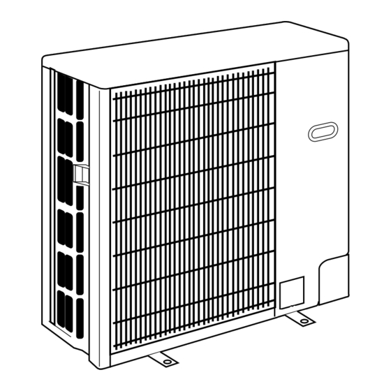
Page 7: Part Names And Functions
PART NAMES AND FUNCTIONS Air outlet (Expels warm air during cooling) Air outlet Air intake Air intake PUH-P1VGAA.UK PU/PUH-P2VGAA.UK PU/PUH-P2YGAA.UK PU/PUH-P1.6VGAA.UK PU/PUH-P2.5VGAA.UK PU/PUH-P2.5YGAA.UK PU/PUH-P1.6YGAA.UK PU/PUH-P3VGAA.UK PU/PUH-P3YGAA.UK PUH-P1VGAA PU/PUH-P2VGAA PU/PUH-P2YGAA PU/PUH-P1.6VGAA PU/PUH-P2.5VGAA .UK PU/PUH-P2.5YGAA PU/PUH-P1.6YGAA PU/PUH-P3VGAA PU/PUH-P3YGAA Air outlet Air outlet... -
Page 8: Heating
SPECIFICATIONS 5-1. SPECIFICATIONS 5-1-1. Heat pump PUH-P1.6VGAA / YGAA.UK PUH-P1VGAA.UK Service Ref. PUH-P1VGAA PUH-P1.6VGAA / YGAA Function Cooling Heating Cooling Heating Single,50Hz,220/230/240V Single,50Hz,220/230/240V / 3-ph,50Hz,380/400/415V Power supply (phase, cycle, voltage) Input 1.11 1.02 1.59 1.64 4.92 4.52 7.36 / 2.49 7.59 / 2.56... -
Page 9: Noise
PUH-P2VGAA / YGAA.UK PUH-P2.5VGAA / YGAA.UK Service Ref. PUH-P2VGAA / YGAA PUH-P2.5VGAA / YGAA Cooling Heating Cooling Heating Function Single, 50Hz, 220/230/240V / 3-ph, 50Hz, 380/400/415V(4wires) Power supply (phase, cycle, voltage) 2.29 2.36 2.77 2.68 Input 10.26 / 3.70 Running current 10.57 / 3.82 11.90 / 4.48 11.51 / 4.34... -
Page 10: Noise
PUH-P3VGAA / YGAA.UK PUH-P4VGAA / YGAA.UK Service Ref. PUH-P3VGAA / YGAA PUH-P4VGAA / YGAA Cooling Heating Cooling Heating Function Power supply (phase, cycle, voltage) Single, 50Hz, 220/230/240V / 3-ph, 50Hz, 380/400/415V(4wires) 3.27 3.48 3.43 3.62 Input Running current 14.81 / 5.29 15.76 / 5.63 15.71 / 5.55 16.58 / 5.86... -
Page 11: Noise
PUH-P5YGAA.UK PUH-P6YGAA.UK Service Ref. PUH-P5YGAA PUH-P6YGAA Cooling Heating Cooling Heating Function 3-ph, 50Hz, 380/400/415V(4wires) Power supply (phase, cycle, voltage) 4.70 5.04 5.58 5.91 Input Running current 7.60 8.15 9.03 9.56 Starting current 65.5 Munsell 5Y 7/1 External finish Linear Expansion Valve Refrigerant control Hermetic Compressor... -
Page 12: Noise
PUH-P5YGAA Service Ref. PUH-P6YGAA Cooling Heating Cooling Heating Function 3-ph, 50Hz, 380/400/415V(4wires) Power supply (phase, cycle, voltage) Input 4.70 5.04 5.58 5.91 Running current 7.60 8.15 9.03 9.56 Starting current 65.5 Munsell 5Y 7/1 External finish Linear Expansion Valve Refrigerant control Hermetic Compressor Model... -
Page 13: Noise
5-1-2. Cooling only type PU-P1.6VGAA / YGAA.UK PU-P2VGAA / YGAA.UK PU-P2.5VGAA / YGAA.UK Service Ref. PU-P1.6VGAA / YGAA PU-P2VGAA / YGAA PU-P2.5VGAA / YGAA Cooling Cooling Cooling Function Single, 50Hz, 220/230/240V / 3-ph, 50Hz, 380/400/415V(4wires) Power supply (phase, cycle, voltage) 1.59 2.29 2.77... -
Page 14: Noise
PU-P3VGAA / YGAA.UK PU-P4VGAA / YGAA.UK Service Ref. PU-P3VGAA / YGAA PU-P4VGAA / YGAA Cooling Function Cooling Single, 50Hz, 220/230/240V / 3-ph, 50Hz, 380/400/415V(4wires) Power supply (phase, cycle, voltage) 3.27 3.43 Input Running current 14.81 / 5.29 15.71 / 5.55 Starting current 93 / 47 99 / 49... -
Page 15: Noise
PU-P5YGAA.UK PU-P6YGAA.UK Service Ref. PU-P5YGAA PU-P6YGAA Function Cooling Cooling 3-ph, 50Hz, 380/400/415V(4wires) Power supply (phase, cycle, voltage) Input 4.70 5.58 7.60 9.03 Running current Starting current 65.5 Munsell 5Y 7/1 External finish Refrigerant control Linear Expansion Valve Hermetic Compressor Model ZR61KCE-TFD-230 (YGAA.UK) ZR72KCW-TFD-522 ZR61KCW-TFD-522 (YGAA... -
Page 16: Noise
PU-P5YGAA PU-P6YGAA Service Ref. Cooling Cooling Function 3-ph, 50Hz, 380/400/415V(4wires) Power supply (phase, cycle, voltage) 4.70 5.58 Input 7.60 9.03 Running current Starting current 65.5 Munsell 5Y 7/1 External finish Refrigerant control Linear Expansion Valve Hermetic Compressor Model BE82YADMT BE96YADMT Motor output Starter type Line start... - Page 17 DATA 6-1. REFILLING REFRIGERANT CHARGE (R407C : kg) Piping length (one way) Factory Service Ref. charged PUH-P1VGAA.UK — — PUH-P1VGAA PU/PUH-P1.6VGAA.UK — PU/PUH-P1.6VGAA PU/PUH-P1.6YGAA.UK — PU/PUH-P1.6YGAA PU/PUH-P2VGAA.UK — PU/PUH-P2VGAA PU/PUH-P2YGAA.UK — PU/PUH-P2YGAA PU/PUH-P2.5VGAA.UK PU/PUH-P2.5VGAA PU/PUH-P2.5YGAA.UK PU/PUH-P2.5YGAA PU/PUH-P3VGAA.UK PU/PUH-P3VGAA PU/PUH-P3YGAA.UK PU/PUH-P3YGAA PU/PUH-P4VGAA.UK...
-
Page 18: Noise
6-3. NOISE CRITERION CURVES MICROPHONE UNIT GROUND PUH-P1VGAA.UK PU/PUH-P1.6VGAA.UK SPL(dB) LINE MODE SPL(dB) LINE MODE COOLING PU/PUH-P1.6VGAA COOLING PUH-P1VGAA HEATING HEATING PU/PUH-P1.6YGAA.UK PU/PUH-P1.6YGAA NC-70 NC-70 NC-60 NC-60 NC-50 NC-50 NC-40 NC-40 NC-30 NC-30 APPROXIMATE APPROXIMATE THRESHOLD OF THRESHOLD OF HEARING FOR... -
Page 19: Table Of Contents
PU/PUH-P3VGAA.UK PU/PUH-P4VGAA.UK SPL(dB) LINE MODE SPL(dB) MODE LINE PU/PUH-P3VGAA PU/PUH-P4VGAA COOLING COOLING HEATING HEATING PU/PUH-P3YGAA.UK PU/PUH-P4YGAA.UK PU/PUH-P3YGAA PU/PUH-P4YGAA NC-70 NC-70 NC-60 NC-60 NC-50 NC-50 NC-40 NC-40 NC-30 NC-30 APPROXIMATE APPROXIMATE THRESHOLD OF THRESHOLD OF HEARING FOR HEARING FOR NC-20 NC-20 CONTINUOUS CONTINUOUS NOISE... -
Page 20: Outlines And Dimensions
OUTLINES AND DIMENSIONS PUH-P1VGAA.UK Unit : mm PUH-P1VGAA PU/PUH-P1.6VGAA.UK PU/PUH-P1.6VGAA PU/PUH-P1.6YGAA.UK PU/PUH-P1.6YGAA... - Page 21 PU/PUH-P2VGAA.UK Unit : mm PU/PUH-P2VGAA PU/PUH-P2YGAA.UK PU/PUH-P2YGAA PU/PUH-P2.5VGAA.UK PU/PUH-P2.5VGAA PU/PUH-P2.5YGAA.UK PU/PUH-P2.5YGAA PU/PUH-P3VGAA.UK PU/PUH-P3VGAA PU/PUH-P3YGAA.UK PU/PUH-P3YGAA...
- Page 22 PU/PUH-P4VGAA.UK Unit : mm PU/PUH-P4VGAA PU/PUH-P4YGAA.UK PU/PUH-P4YGAA...
- Page 23 PU/PUH-P5YGAA.UK Unit : mm PU/PUH-P5YGAA PU/PUH-P5YGAA PU/PUH-P6YGAA.UK PU/PUH-P6YGAA PU/PUH-P6YGAA...
-
Page 24: Wiring Diagram
WIRING DIAGRAM PUH-P1, P1.6, P2, P2.5, P3, P4VGAA.UK PUH-P1, P1.6, P2, P2.5, P3, P4VGAA SYMBOL NAME SYMBOL NAME COMPRESSOR (INNER THERMOSTAT) OUTDOOR CONTROLLER BOARD FAN MOTOR (INNER THERMOSTAT) FUSE1 (O.B) FUSE (6.3A) THERMISTOR LIQUID TEMP FUSE2 (O.B) FUSE (6.3A) DISCHARGE TEMP FUSE3 (O.B) FUSE (6.3A) COND. - Page 25 PUH-P1.6, P2, P2.5, P3, P4, P5, P6YGAA.UK PUH-P1.6, P2, P2.5, P3, P4, P5, P6YGAA SYMBOL NAME SYMBOL NAME COMPRESSOR OUTDOOR CONTROLLER BOARD FAN MOTOR (INNER THERMOSTAT) FUSE1 (O.B) FUSE (6.3A) THERMISTOR LIQUID TEMP FUSE2 (O.B) FUSE (6.3A) DISCHARGE TEMP FUSE3 (O.B) FUSE (6.3A) COND.
- Page 26 PU-P1.6, P2, P2.5, P3, P4VGAA.UK PU-P1.6, P2, P2.5, P3, P4VGAA SYMBOL NAME SYMBOL NAME COMPRESSOR (INNER THERMOSTAT) OUTDOOR CONTROLLER BOARD FAN MOTOR (INNER THERMOSTAT) FUSE1 (O.B) FUSE (6.3A) THERMISTOR LIQUID TEMP FUSE2 (O.B) FUSE (6.3A) DISCHARGE TEMP FUSE3 (O.B) FUSE (6.3A) COND.
- Page 27 PU-P1.6, P2, P2.5, P3, P4, P5, P6YGAA.UK PU-P1.6, P2, P2.5, P3, P4, P5, P6YGAA SYMBOL NAME SYMBOL NAME COMPRESSOR OUTDOOR CONTROLLER BOARD FAN MOTOR (INNER THERMOSTAT) FUSE1 (O.B) FUSE (6.3A) THERMISTOR LIQUID TEMP FUSE2 (O.B) FUSE (6.3A) DISCHARGE TEMP FUSE3 (O.B) FUSE (6.3A) FUSE4 (O.B) FUSE (6.3A)
- Page 28 PUH-P5YGAA PUH-P6YGAA SYMBOL NAME SYMBOL NAME COMPRESSOR OUTDOOR CONTROLLER BOARD FAN MOTOR (INNER THERMOSTAT) FUSE1 (O.B) FUSE (6.3A) THERMISTOR LIQUID TEMP FUSE2 (O.B) FUSE (6.3A) DISCHARGE TEMP FUSE3 (O.B) FUSE (6.3A) COND. / EVA. TEMP FUSE4 (O.B) FUSE (6.3A) MF CAPACITOR (O.B) MC/CH RELAY MF CAPACITOR...
- Page 29 PU-P5YGAA PU-P6YGAA SYMBOL NAME SYMBOL NAME COMPRESSOR OUTDOOR CONTROLLER BOARD FAN MOTOR (INNER THERMOSTAT) FUSE1 (O.B) FUSE (6.3A) THERMISTOR LIQUID TEMP FUSE2 (O.B) FUSE (6.3A) DISCHARGE TEMP FUSE3 (O.B) FUSE (6.3A) COND. / EVA. TEMP FUSE4 (O.B) FUSE (6.3A) MF CAPACITOR (O.B) MC/CH RELAY MF CAPACITOR...
-
Page 30: Wiring Specifications
WIRING SPECIFICATIONS PU/PUH-P1VGAA.UK~P6YGAA.UK WIRING SPECIFICATIONS FOR 220~240V 50Hz PU/PUH-P1VGAA .UK~P6YGAA (INDOOR-OUTDOOR CONNECTING CABLE) PU/PUH-P5VGAA .UK~P6YGAA (Except PUH-8YE,PUH-10YE) Wire size Number L(m) Cross section Polarity of wires of cable Round Clockwise : S1-S2-S3 (50) w Pay attention to stripe of yellow and green... -
Page 31: Refrigerant System Diagram
REFRIGERANT SYSTEM DIAGRAM PUH-P1, P1.6, P2, P2.5, P3VGAA.UK PUH-P1.6, P2, P2.5, P3YGAA.UK <4-way valve solenoid coil> Heating : ON Refrigerant pipe Ball valve High pressure Outdoor unit Cooling : OFF P1···12.7A({1/2") 4-way valve protect switch Indoor unit Outdoor heat exchanger P1.6~P3···15.88A({5/8") (#50) (with heat insulator) - Page 32 PU-P1.6, P2, P2.5, P3VGAA.UK PU-P1.6, P2, P2.5, P3YGAA.UK High pressure Outdoor unit Refrigerant pipe Ball valve protect switch Indoor unit Outdoor heat exchanger 15.88A({5/8") (#50) (with heat insulator) Strainer Thermistor (TH6) Thermistor Flexible tube (TH1) Service Service Thermistor port port (TH3) Flared Strainer...
-
Page 33: Heating
PUH-P1, P1.6, P2, P2.5, P3VGAA PUH-P1.6, P2, P2.5, P3YGAA <4-way valve solenoid coil> Heating : ON Refrigerant pipe High pressure Ball valve Outdoor unit Cooling : OFF P1···12.7A({1/2") 4-way valve protect switch Indoor unit Outdoor heat exchanger P1.6~P3···15.88A({5/8") (#50) (with heat insulator) Strainer Thermistor (TH6) -
Page 34: Cooling
PU-P1.6, P2, P2.5, P3VGAA PU-P1.6, P2, P2.5, P3YGAA High pressure Outdoor unit Refrigerant pipe Ball valve protect switch Indoor unit Outdoor heat exchanger 15.88A({5/8") (#50) (with heat insulator) Strainer Thermistor (TH6) Thermistor Flexible tube (TH1) Service Thermistor Service port (TH3) port Flared Strainer... -
Page 35: Noise
TROUBLESHOOTING 11-1. SELF-DIAGNOSTIC FUNCTION • The blinking patterns of two LEDs—LED1(Green) and LED2(Red)—show the diagnoses of troubles in case of malfunction. • By 7SEG indicator board indicates the operation mode and inspection types. For the details, refer to “OCT03 REVISED EDITION-C”. - Page 36 From the preceding page. Indication (O.B) Error Name Inspection method LED1 LED2 (Green) (Red) 1 Check if ball valves are open. 3 blinks 1 blink •Abnormal high discharge temperature(TH4) 2 Check the continuity of connector (TH4) on outdoor controller board by using a tester. 3 Check if the unit fills the refrigerant at the same amount as specified.
-
Page 37: Continuous
11-2. SELF-DIAGNOSIS ACTION TABLE <Abnormalities detected when the power is put on> (Note 1) The number in ( ) is the error cord of upper remote controller (M-NET) Error Code Meaning of error code and detection method Case Judgment and action 1 No voltage is supplied to termi- 1 Check following items. -
Page 38: Noise
Case Error Code Meaning of error code and detection method Judgment and action 1 Check disconnection or looseness or polarity Indoor/outdoor unit connector mis- 1 Contact failure or mis-wiring of wiring, excessive number of units (5 indoor/outdoor unit connecting of indoor/outdoor unit connecting wire of units or more) wire. -
Page 39: Continuous
Case Error Code Meaning of error code and detection method Judgment and action 1 Short cycle of indoor unit 1-6 Check indoor unit and repair defectives. Abnormal high pressure (High-pressure switch 63H worked) 2 Clogged filter of indoor unit 7 Check full open stop valve. Abnormal if high-pressure switch 63H 3 Decreased airflow caused by 8 Check piping and repair defectives. -
Page 40: Heating
Case Error Code Meaning of error code and detection method Judgment and action 1 Over-heated compressor oper- 1 Check intake super heat. Inner thermostat (49C) working detector Abnormal if inner thermostat (49C) works ation caused by shortage of Check leakage of refrigerant. during compressor operation. -
Page 41: Continuous
Error Code Meaning of error code and detection method Case Judgment and action 1 Abnormal compressor 1 Check compressor. Compressor over current (start-up 2 Clogged indoor filter locked) breaking Refer to 6-2. Abnormal if compressor current exceeds 3 Open-phase compressor 2 Check indoor unit and repair defective. -
Page 42: Continuous
Error Code Meaning of error code and detection method Case Judgment and action Indoor/outdoor unit communication 1 Defective communication circuit 123 Put the power off, and on again to error (Transmitting error) of outdoor controller check. Replace outdoor controller board 2 Noise has entered power supply. -
Page 43: Continuous
Error Code Meaning of error code and detection method Case Judgment and action NO ACK Common factor that has no rela- Always try the followings when the error tion with abnormality source. 1. Transmitting side controller detects “A7” occures. 1 The unit of former address abnormal if a massage was transmitted does not exist as address 1 Shut off the power supply of outdoor unit and... -
Page 44: Continuous
From the previous page. Error Code Meaning of error code and detection method Case Judgment and action 1 During sequential operation of Same as mentioned in “A7” of the previous 5. If displayed address or attribute is page. FRESH MASTER, indoor unit and FRESH MAS- TER of other refrigerant sys- Indoor unit detects abnormality when... - Page 45 11-3. HOW TO CHECK THE PARTS PUH-P1, P1.6, P2, P2.5, P3, P4VGAA.UK PUH-P1.6, P2, P2.5, P3, P4, P5, P6YGAA.UK PUH-P1, P1.6, P2, P2.5, P3, P4VGAA .UK PUH-P1.6, P2, P2.5, P3, P4, P5, P6YGAA PUH-P5, P6YGAA PU-P1.6, P2, P2.5, P3, P4VGAA.UK PU-P1.6, P2, P2.5, P3, P4, P5, P6YGAA.UK PU-P1.6, P2, P2.5, P3, P4VGAA PU-P1.6, P2, P2.5, P3, P4, P5, P6YGAA...
-
Page 46: Linear Expansion Valve
<Thermistor characteristic graph> < Thermistor for lower temperature > Liquid temperature thermistor(TH3) Thermistor for Condenser/evaporator temperature lower temperature thermistor(TH6) Thermistor R =15k' ± 3% Fixed number of B=3480 ± 2% Rt=15exp { 3480( 273+t 15k' 9.6k' 6.3k' 5.2k' 4.3k' 3.0k' -20 -10 10 20 30 40 50 Temperature (:) -
Page 47: Noise
<Output pulse signal and the valve operation> Output Output (Phase) Closing a valve : 1 Opening a valve : 4 The output pulse shifts in above order. 1. When linear expansion valve operation stops, all output phase become OFF. 2. At phase interruption or when phase does not shift in order, motor does not rotate smoothly and motor will locks and vibrates. - Page 48 11-4. TEST POINT DIAGRAM Outdoor controller board PUH-P1, P1.6, P2, P2.5, P3, P4VGAA.UK PUH-P1.6, P2, P2.5, P3, P4, P5, P6YGAA.UK PUH-P1, P1.6, P2, P2.5, P3, P4VGAA PUH-P1.6, P2, P2.5, P3, P4, P5, P6YGAA PUH-P5, P6YGAA PU-P1.6, P2, P2.5, P3, P4VGAA.UK PU-P1.6, P2, P2.5, P3, P4, P5, P6YGAA.UK PU-P1.6, P2, P2.5, P3, P4VGAA PU-P1.6, P2, P2.5, P3, P4, P5, P6YGAA...
-
Page 49: Disassembly Procedure
DISASSEMBLY PROCEDURE Note : The following photos are PUH-P5/P6YGAA.UK and PUH-P5YGAA.UK PUH-P6YGAA.UK PUH-P5/P6YGAA .UK except photo 7. PUH-P5YGAA .UK PUH-P6YGAA PUH-P5YGAA .UK PUH-P6YGAA PUH-P5/P6YGAA .UK is used for photo 7. OPERATING PROCEDURE PHOTOS 1. Removing the Service panel and Top panel Photo 1 Top panel screws Top panel... - Page 50 OPERATING PROCEDURE PHOTOS 4. Removing the liquid temperature thermistor, discharge Photo 4 temperature thermistor and condenser/evaporator temperature thermistor Condenser/evaporator Clamp (1) Remove the service panel. (See Photo 1) temperature thermistor (2) Remove the top panel. (See Photo 1) (When the top panel removing is not possible, remove the electric parts box.
- Page 51 OPERATING PROCEDURE PHOTOS 9. Removing the high pressure switch Photo 6 (1) Remove the service panel. (See Photo 1) Lead wire (2) Remove the top panel. (See Photo 1) (3) Remove the electrical box. (See Photo 3) (4) Disconnect the lead wire of the pressure switch. (See Photo 6) Capillary (5) Remove the braze part of the pressure switch.
- Page 52 OPERATING PROCEDURE PHOTOS 12. Removing the Bell mouth Photo 9 Bell mouth fixing screw (1) Remove the 6 fan guard fixing screws (5 15) to remove it. (See Photo 1) (2) Remove the top panel. (3) Remove a bell mouth fixing screw (5 15) to remove it.
-
Page 53: Parts List
PARTS LIST STRUCTURAL PARTS PUH-P1VGAA.UK PUH-P1VGAA PUH-P1.6VGAA.UK PUH-P1.6VGAA PUH-P1.6YGAA.UK PUH-P1.6YGAA PU-P1.6VGAA.UK PU-P1.6VGAA PU-P1.6YGAA.UK PU-P1.6YGAA ty/set Price Wiring Recom- PUH-P1 PUH-P1.6 PU-P1.6 Remarks Part No. Part Name Specification mended Diagram (Drawing No.) Symbol Unit Amount VGAA VGAA YGAA VGAA YGAA VGAA... - Page 54 STRUCTURAL PARTS PUH-P2VGAA.UK PUH-P2VGAA PUH-P2YGAA.UK PUH-P2YGAA PU-P2VGAA.UK PU-P2VGAA PU-P2YGAA.UK PU-P2YGAA 9 10 11 12 ty/set Price Wiring Recom- Remarks PUH-P2 .UK PU-P2 .UK Part No. Part Name Specificatio Diagram mended (Drawing No.) VGAA YGAA VGAA YGAA Unit Amount Symbol VGAA YGAA VGAA YGAA...
- Page 55 STRUCTURAL PARTS PUH-P2.5VGAA.UK PUH-P2.5VGAA PUH-P2.5YGAA.UK PUH-P2.5YGAA PU-P2.5VGAA.UK PU-P2.5VGAA PU-P2.5YGAA.UK PU-P2.5YGAA 9 10 11 12 ty/set Price Wiring Recom- Remarks PUH-P2.5 .UK PU-P2.5 .UK Part No. Part Name Specificatio Diagram mended (Drawing No.) VGAA YGAA VGAA YGAA Unit Amount Symbol VGAA YGAA VGAA YGAA...
- Page 56 STRUCTURAL PARTS PUH-P3VGAA.UK PUH-P3VGAA PUH-P3YGAA.UK PUH-P3YGAA PU-P3VGAA.UK PU-P3VGAA PU-P3YGAA.UK PU-P3YGAA 9 10 11 12 ty/set Price Wiring Recom- PUH-P3 .UK PU-P3 .UK Remarks Part No. Part Name Specificatio Diagram mended (Drawing No.) VGAA YGAA VGAA YGAA Unit Amount Symbol VGAA YGAA VGAA YGAA...
- Page 57 STRUCTURAL PARTS PUH-P4VGAA.UK PUH-P4VGAA PU-P4VGAA.UK PU-P4VGAA PUH-P4YGAA.UK PUH-P4YGAA PU-P4YGAA.UK PU-P4YGAA 10 11 ty/set Price Recom- Wiring Remarks PUH-P4 .UK PU-P4 .UK Specification Part No. Part Name Diagram mended (Drawing No.) VGAA YGAA VGAA YGAA Symbol Unit Amount VGAA YGAA VGAA YGAA S70 30L 641 TOP PANEL...
- Page 58 STRUCTURAL PARTS PUH-P5YGAA.UK PUH-P5YGAA PUH-P6YGAA.UK PUH-P6YGAA PU-P5YGAA.UK PU-P5YGAA PU-P6YGAA.UK PU-P6YGAA 17 16 ty/set Price Wiring Recom- PUH-P5,6 PU-P5,6 Remarks Part No. Part Name Specification Diagram mended YGAA.UK YGAA.UK Symbol (Drawing No.) Unit Amount YGAA YGAA S70 17T 641 TOP PANEL (5 15) (DG12F536H15) —...
- Page 59 STRUCTURAL PARTS PUH-P5YGAA PUH-P6YGAA PU-P5YGAA 17 16 PU-P6YGAA ty/set Price Wiring Recom- Remarks Part No. Part Name Specification PUH-P5,6 PU-P5,6 Diagram mended (Drawing No.) Symbol Unit Amount YGAA .UK YGAA S70 17T 641 TOP PANEL (5 15) F.ST SCREW S71 000 051 REAR SUPPORT S70 98W 613 FRONT SUPPORT...
- Page 60 FUNCTIONAL PARTS PUH-P1VGAA.UK PUH-P1VGAA FUSE...
- Page 61 ty/set Price Wiring Recom- Remarks Part No. Part Name Specification PUH-P1V Diagram mended Unit Amount Symbol GAA.UK GAA S70 249 708 CONTACTOR S-U12 240V 2P(L,N) S70 E03 716 TERMINAL BLOCK 3P(S1,S2,S3) S70 E04 716 TERMINAL BLOCK S70 E03 763 N026P72MT OUTDOOR FAN MOTOR S70 30L 115 PROPELLER FAN 4...
- Page 62 FUNCTIONAL PARTS PUH-P1.6VGAA.UK PUH-P1.6VGAA PU-P1.6VGAA.UK PU-P1.6VGAA FUSE...
- Page 63 Part number that is circled is not shown in the figure. ty/set Price Wiring Recom- PUH-P1.6V PU-P1.6V Remarks Part No. Part Name Specification Diagram mended Unit Amount Symbol S70 249 708 CONTACTOR S-U12 240V 2P(L,N) S70 E03 716 TERMINAL BLOCK 3P(S1,S2,S3) S70 E04 716 TERMINAL BLOCK...
- Page 64 FUNCTIONAL PARTS PUH-P1.6YGAA.UK PUH-P1.6YGAA PU-P1.6YGAA.UK PU-P1.6YGAA FUSE...
- Page 65 Part number that is circled is not shown in the figure. ty/set Price Wining Recom- PUH-P1.6Y PU-P1.6Y Remarks Part No. Part Name Specification Diagram mended Unit Amount Symbol S70 250 708 CONTACTOR MSO-N11 51C,52C 4P(L1,L2,L3,N) S70 E03 716 TERMINAL BLOCK 3P(S1,S2,S3) S70 E04 716 TERMINAL BLOCK...
- Page 66 FUNCTIONAL PARTS PUH-P2VGAA.UK PUH-P2VGAA PU-P2VGAA.UK PU-P2VGAA FUSE 10 11...
- Page 67 Part number that is circled is not shown in the figure. ty/set Price Wiring Recom- Part No. Part Name Specification PUH-P2V PU-P2V Remarks Diagram mended Unit Amount Symbol GAA.UK GAA .UK GAA.UK GAA S70 330 708 CONTACTOR S-N18EX S70 E03 716 TERMINAL BLOCK 2P(L,N) S70 E04 716...
- Page 68 FUNCTIONAL PARTS PUH-P2.5VGAA.UK PUH-P2.5VGAA PU-P2.5VGAA.UK PU-P2.5VGAA FUSE 10 11...
- Page 69 Part number that is circled is not shown in the figure. ty/set Price Wiring Recom- Part No. Part Name Specification PUH-P2.5V PU-P2.5V Remarks Diagram mended Unit Amount Symbol GAA.UK GAA .UK GAA.UK GAA S70 330 708 CONTACTOR S-N18EX S70 E03 716 TERMINAL BLOCK 2P(L,N) S70 E04 716...
- Page 70 FUNCTIONAL PARTS PUH-P3VGAA.UK PUH-P3VGAA PU-P3VGAA.UK PU-P3VGAA FUSE 10 11...
- Page 71 Part number that is circled is not shown in the figure. ty/set Price Wiring Recom- Part No. Part Name Specification PUH-P3V PU-P3V Remarks Diagram mended Unit Amount Symbol GAA.UK GAA .UK GAA.UK GAA S70 330 708 CONTACTOR S-N18EX S70 E03 716 TERMINAL BLOCK 2P(L,N) S70 E04 716...
- Page 72 FUNCTIONAL PARTS PUH-P2YGAA.UK PUH-P2YGAA PU-P2YGAA.UK PU-P2YGAA FUSE 10 11...
- Page 73 Part number that is circled is not shown in the figure. ty/set Price Wiring Recom- Part No. Part Name Specification PUH-P2Y PU-P2Y Remarks Diagram mended Unit Amount Symbol GAA.UK GAA .UK GAA.UK GAA S70 332 708 CONTACTOR MSO-N11 51C,52C S70 E10 716 TERMINAL BLOCK 4P(L1,L2,L3,N) S70 E04 716...
- Page 74 FUNCTIONAL PARTS PUH-P2.5YGAA.UK PUH-P2.5YGAA PU-P2.5YGAA.UK PU-P2.5YGAA FUSE 10 11...
- Page 75 Part number that is circled is not shown in the figure. ty/set Price Wiring Recom- Part No. Part Name Specification PUH-P2.5Y PU-P2.5Y Remarks Diagram mended Unit Amount Symbol GAA.UK GAA .UK GAA.UK GAA S70 333 708 CONTACTOR MSO-N11 51C,52C S70 E10 716 TERMINAL BLOCK 4P(L1,L2,L3,N) S70 E04 716...
- Page 76 FUNCTIONAL PARTS PUH-P3YGAA.UK PUH-P3YGAA PU-P3YGAA.UK PU-P3YGAA FUSE 10 11...
- Page 77 Part number that is circled is not shown in the figure. ty/set Price Wiring Recom- Part No. Part Name Specification PUH-P3Y PU-P3Y Remarks Diagram mended Unit Amount Symbol GAA.UK GAA .UK GAA.UK GAA S70 331 708 CONTACTOR MSO-N11 51C,52C S70 E10 716 TERMINAL BLOCK 4P(L1,L2,L3,N) S70 E04 716...
- Page 78 FUNCTIONAL PARTS PUH-P4VGAA.UK PUH-P4VGAA PU-P4VGAA.UK PU-P4VGAA FUSE 27 26...
- Page 79 Part number that are circled are not shown in the figure. ty/set Price Wiring Recom- Remarks Part No. Part Name Specification PUH-P4V PU-P4V Diagram mended Unit Amount Symbol GAA.UK GAA GAA.UK N026P72MT S70 E03 763 OUTDOOR FAN MOTOR S70 30L 115 PROPELLER FAN 4 S70 30L 097 S70 E05 408...
- Page 80 FUNCTIONAL PARTS PUH-P4YGAA.UK PUH-P4YGAA PU-P4YGAA.UK PU-P4YGAA FUSE 27 26...
- Page 81 Part number that is circled is not shown in the figure. ty/set Price Wining Recom- Remarks Part No. Part Name Specification PUH-P4Y PU-P4Y Diagram mended Unit Amount Symbol GAA.UK GAA GAA.UK S70 E03 763 OUTDOOR FAN MOTOR N026P72MT S70 30L 115 PROPELLER FAN 4 S70 30L 097 S70 E05 408...
- Page 82 FUNCTIONAL PARTS PUH-P5YGAA.UK PUH-P5YGAA PU-P5YGAA.UK PU-P5YGAA FUSE 33 32 31 30...
- Page 83 Part number that are circled are not shown in the figure. ty/set Price Wiring Recom- Remarks PUH-P5Y PU-P5Y Part No. Part Name Specification Diagram mended Unit Amount Symbol GAA.UK GAA .UK GAA.UK GAA OUTDOOR FAN MOTOR S70 E03 763 N026P72MT PROPELLER FAN 4 S70 30L 115 S70 30L 097...
- Page 84 FUNCTIONAL PARTS PUH-P5YGAA PU-P5YGAA FUSE 33 32 31 30...
- Page 85 Part number that is circled is not shown in the figure. ty/set Price Wiring Recom- Remarks Part No. Part Name Specification Diagram mended PUH-P5 PU-P5 Unit Amount Symbol YGAA YGAA OUTDOOR FAN MOTOR S70 E03 763 N026P72MT PROPELLER FAN 4 S70 30L 115 S70 30L 097 DOME CAP NUT...
- Page 86 FUNCTIONAL PARTS PUH-P6YGAA.UK PUH-P6YGAA PU-P6YGAA.UK PU-P6YGAA FUSE 33 32 31 30...
- Page 87 Part number that are circled are not shown in the figure. ty/set Price Wiring Recom- Remarks PUH-P6Y PU-P6Y Part No. Part Name Specification Diagram mended Unit Amount Symbol GAA.UK GAA.UK OUTDOOR FAN MOTOR S70 E03 763 N026P72MT S70 30L 115 PROPELLER FAN 4 S70 30L 097 HEAT EXCHANGER...
- Page 88 FUNCTIONAL PARTS PUH-P6YGAA PU-P6YGAA FUSE 33 32 31 30...
- Page 89 Part number that is circled is not shown in the figure. ty/set Price Wiring Recom- Remarks Part No. Part Name Specification Diagram mended PUH-P6 PU-P6 Unit Amount Symbol YGAA YGAA OUTDOOR FAN MOTOR S70 E03 763 N026P72MT PROPELLER FAN 4 S70 30L 115 S70 30L 097 DOME CAP NUT...
-
Page 90: Optional Parts
PU/PUH-P • GAA HEAD OFFICE : MITSUBISHI DENKI BLDG., 2-2-3, MARUNOUCHI, CHIYODA-KU TOKYO 100-8310, JAPAN cCopyright 2001 MITSUBISHI ELECTRIC ENGINEERING CO., LTD. Distributed in Feb. 2005. No.OC261 REVISED EDITION-D PDF 8 Distributed in Feb. 2005. No.OC261 REVISED EDITION-C PDF 8 Distributed in Feb.