Table of Contents
Advertisement
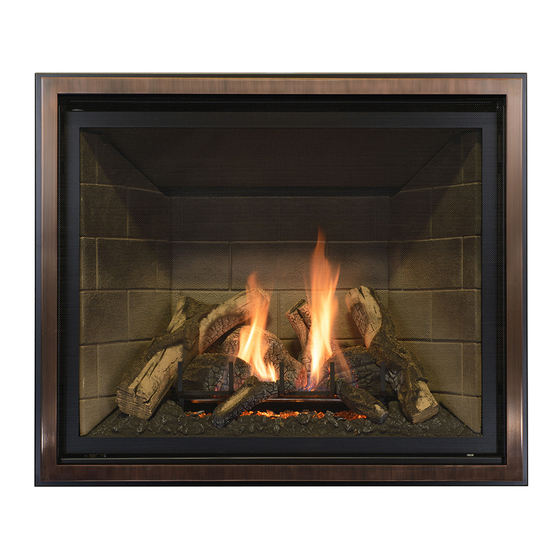
INSTALLATION AND OPERATION MANUAL
MODEL #BAY-41-G
Report No. 216-F-41b-6.5
WARNING: If the informa on in these
instruc ons are not followed exactly, a fire or
explosion
may
damage, personal injury, or loss of life.
Do not store or use gasoline or other
flammable vapors and liquids in the vicinity
of this or any other appliance.
WHAT TO DO IF YOU SMELL GAS
Do not try to light any appliance.
Do not touch any electrical switch; do not
use any phone in your building.
Immediately call gas supplier from a
neighbors phone. Follow the gas supplier
instruc ons.
If you cannot reach your gas supplier, call
the fire department.
Installa on and service must be performed
by a qualified installer, service agency or the
gas supplier.
English and French installa on
manuals available through your
local dealer, or visit our website
www.kozyheat.com
result
causing
property
A barrier designed to reduce the risk of burns from the hot viewing glass is
provided with this appliance and shall be installed.
BAY-41-G ● REV-04 ● December 2013
INSTALLER: Leave this manual with the appliance.
CONSUMER: Retain this manual for future reference.
This appliance may be installed in an
a ermarket,
manufactured home (USA only) or mobile
home, where not prohibited by local codes.
This appliance is only for use with the type of
gas indicated on the ra ng plate. This
appliance is not conver ble for use with other
gases, unless a cer fied kit is used.
WARNING
HOT GLASS WILL CAUSE BURNS.
DO NOT TOUCH GLASS UNTIL COOLED.
NEVER ALLOW CHILDREN TO TOUCH GLASS.
HUSSONG MFG. CO., INC.
permanently
located,
Advertisement
Table of Contents

Related Manuals for kozy heat Bayport-41-G


Summary of Contents for kozy heat Bayport-41-G
- Page 1 INSTALLATION AND OPERATION MANUAL MODEL #BAY-41-G HUSSONG MFG. CO., INC. Report No. 216-F-41b-6.5 WARNING: If the informa on in these INSTALLER: Leave this manual with the appliance. instruc ons are not followed exactly, a fire or CONSUMER: Retain this manual for future reference. explosion result causing...
- Page 2 Read this manual before installing or operating this appliance. Please retain this owner’s manual for future reference. CONGRATULATIONS! We welcome you as a new owner of a Kozy Heat gas fireplace. Kozy Heat products are designed with superior components and materials; assembled by trained craftsmen who take pride in their work. The burner and valve assembly are 100% test-fired, and the complete fireplace is thoroughly inspected before packaging to ensure you receive a quality product.
-
Page 3: Table Of Contents
TABLE OF CONTENTS HOMEOWNER REFERENCE INFORMATION #970 HEAT DUCT KIT TABLE OF CONTENTS Specifications INTRODUCTION Attach Duct to Fireplace Appliance Certification Install Register Mounting Frame and Junction Box Safety Information R.04 Install and Wire Fan Assembly Commonwealth of Massachusetts Requirements Run and Secure Duct Pipe Installation Overview Complete the Installation... -
Page 4: Introduction
INTRODUCTION Appliance Certification This appliance has been tested by OMNI-Test Laboratories located in Portland, Oregon and complies with: ANSI Z21.88a-2012/CSA 2.33a-2012, “Vented Gas Fireplace Heaters” CGA 2.17-M91 (R2009), “Gas-Fired Appliances for Use at High Altitudes” CSA P.4.1-2009, “Testing Method for Measuring Annual Fireplace Efficiency” This installation must conform with local codes, or in the absence of local codes, with the National Fuel Gas Code, ANSI Z223.1/NFPA 54, or the Natural Gas and Propane Installation Code, CSA B149.1. -
Page 5: Commonwealth Of Massachusetts Requirements
Commonwealth of Massachusetts Requirements The following requirements reference various Massachusetts and national codes not contained in this manual. For all sidewall horizontally vented gas fueled equipment installed in every dwelling, building or structure used in whole or in part for residential purposes, including those owned or operated by the Commonwealth and where the side wall exhaust vent termination is less than (7) feet above finished grade in the area of the venting, including but not limited to decks and porches, the following requirements shall be satisfied:... -
Page 6: Installation Overview
Installation Overview NOTE The qualified installer should follow the procedure best suited for the installation. Frame an opening for the fireplace, allowing for vent installation (top or rear) and type of installation (corner or flat wall application). Refer 4.0, Framing and Clearances, 9.0, Venting, and 4.0, Typical Installation Options. If masonry (optional) is used, prepare foundation for the masonry load. -
Page 7: Specifications
SPECIFICATIONS Components List PART NUMBER DESCRIPTION B41G-150 Control Board Assembly 700-203 Manual Gas Shut-off Valve B41G-135 Burner Assembly B41-057T Glass Frame Assembly IPI-028 Fan Kit (2)-75 CFM 700-408 Remote Control BTU Specifications BAY-41-G Fuel Minimum Input BTU/hr. (kW) Maximum Input BTU/hr. (kW) Orifice Size Natural Gas 15,000 BTU/hr (4.4 kW) -
Page 8: Appliance Dimensions
Appliance Dimensions WARNING All stand-off brackets must be attached to fireplace. Do not remove. Top stand-off brackets are not load bearing. All clearances must be maintained. Other clearances apply. Table 2.1 Physical Dimensions Unit Top to Unit Top to Back to Floor to Back Opening... -
Page 9: Framing And Clearances
FRAMING AND CLEARANCES Appliance Location and Installation Table 3.1, Minimum Placement Clearances To flooring 0 in. 0 mm Appliance top to ceiling 31 in. 787 mm Appliance side to adjacent sidewall 1 in. 25 mm Appliance front to combustibles 36 in. 914 mm ... -
Page 10: Nailing Flange Assembly And Installation
Nailing Flange Assembly and Installation NOTE Depending on facing material, tabs can be adjusted forward or backward up to 1/2 in. (13 mm). CAUTION Never permanently remove these assemblies from the fireplace—they must be secured regardless of finish material used. Remove (4) nailing flanges from the right and left side of the fireplace. -
Page 11: Hearth Information
Hearth Information If masonry is to be used (optional), prepare the necessary foundation for the masonry load. When masonry construction is being used, a lintel must be used over top of fireplace to support the added weight. Build the hearth to desired size and height. If a hearth extension is desired, combustible material may be used. ... -
Page 12: Vent Termination Framing
Vent Termination Framing IMPORTANT Vent cap location must be in compliance with the guidelines 8.9, Termination Vent Cap Location and Clearances, on page 26. WARNING DO NOT RECESS THE VENT CAP INTO WALL OR SIDING. 3.6.1 Vertical Vent Terminations Follow vent pipe manufacturer’s installation instructions for vertical vent termination framing. -
Page 13: Typical Installation Options
TYPICAL INSTALLATION OPTIONS IMPORTANT 1/2 in. (13 mm) wall materials included in dimensions where applicable. Modify minimum opening if necessary to accommodate finish material thickness. Figure 4.2, Top Vent Vertical Figure 4.1, Corner Figure 4.3, Top Vent Horizontal Figure 4.4, Rear Vent Vertical 28”... -
Page 14: Facing And Finishing
FACING AND FINISHING Provide adequate clearance in front of the fireplace to remove safety barrier, to operate lower grill, to access components, to install gas line, and other components. Non-combustible material may be applied over, but not attached, to the fireplace face. This will prevent non-combustible material from falling off the fireplace face due to heat expansion. -
Page 15: Safety Barriers
R.05 Safety Barriers Table 5.2, Safety Barrier Fit and Mounting Clearances Models Above the fireplace Below the Fireplace Depth from Fireplace #B41-RSF, #B41-FRSF-BS, Bottom of safety barrier must #B41R-MSF, #B41R-CSF, be level with finished hearth; 1/4” (6 mm) #B41-FRSF, #B41A-MSF*, except model #B41-RSF Notched tabs allow to set #B41-PSF*... - Page 16 Figure 5.3, Models #B41-BSF,#B41-FRSF, #B41-FRSF-BS, #B41R-CSF, and #B41R-MSF Dimensions B41-BSF B41-FRSF B41-FRSF-BS FULL RECTANGULAR SCREEN FRONT FULL RECTANGULAR SCREEN FRONT—BRUSHED STEEL (Top and Sides Overlap) (Top and Sides Overlap) B41R-CSF B41R-MSF RECTANGULAR MISSION SCREEN FRONT (Top and Sides Overlap)
- Page 17 5.2.3 Overlap Fit - Direct Mount Installation Option Direct Mount Installation Option for Models #B41A-MSF and #B41-PSF (recommended for low clearance applications) Locate the (4) acorn nuts on the left and right side of the Figure 5.4, #B41-PSF Direct Mount Installation screen front face (2 each side).
-
Page 18: Gas Line Connection
GAS LINE CONNECTION CAUTION Installation of the gas line must only be done by a qualified person in accordance with local building codes, if any. If not, follow ANSI 223.1. Commonwealth of Massachusetts: Installation must be done by a licensed plumber or gas fitter. NOTE A listed (and Commonwealth of Massachusetts approved) 1/2 in. -
Page 19: Wiring Schematics
WIRING SCHEMATICS IMPORTANT This system requires 120V of electricity / batteries to operate. Figure 7.1, IFC Control Module Wiring... -
Page 20: Venting
VENTING Top Vent Conversion Instructions IMPORTANT This appliance has outlets for both top and rear venting. The unused vent exit must have the appropriate cover plates in place and the cover plate must be removed according to instructions from the exit to be used. NOTE All components removed from the fireplace rear vent will be re-installed for the top vent. - Page 21 8.1.3 Install Exhaust and Combustion Air Intake Collars to the Fireplace Top Install gasket and 4” (101 mm) exhaust collar to fireplace top. Secure with (6) screws previously removed. Install gasket and 6-5/8” (168 mm) combustion air intake collar to fireplace top. Secure with (4) screws previously removed. Insert tabs on top cover plate into slots at top of fireplace.
-
Page 22: Approved Vent Systems
IMPORTANT Consult the local and national installation codes to assure adequate combustion and ventilation air is available. Flame height and ap- pearance will vary depending upon venting configuration and the type of fuel used. Venting requirements apply to both natural gas and LP gas. Approved Vent Systems ... -
Page 23: Venting For Horizontal Terminations
Venting for Horizontal Terminations IMPORTANT Horizontal vent sections require 1/4 in. (6 mm) rise for every 12 in. (305 mm) of travel. A wall thimble pass-through must be used on all horizontal vent runs that pass through interior or exterior walls. Follow vent system manufacturer’s instructions. -
Page 24: Corner Installations
Figure 8.8, Natural Gas & LP Gas Min/Max Horizontal Venting 90° Elbow BAY-41-G (NG / LPG) Minimum Minimum Maximum Termination Vertical Rise Horizontal Run Horizontal Run 15 in. 381 mm 6 in. 152 mm 48 in. 1219 mm Min: 15” (381mm) Min: 6”... -
Page 25: Venting For Vertical Terminations
Venting for Vertical Terminations 8.5.1 Vertical Vent Section Clearances Table 8.3, All Approved Venting Systems, Clearances to Combustible Material All Sides Vent Pipe Surface Clearances 1 in. (25 mm) 8.5.2 Top Vent Vertical Venting Configurations Figure 8.11, Top Vent Vertical Venting BAY-41-G (NG / LPG) Termination cap Minimum... -
Page 26: Elbows
Elbows For each additional 90° elbow used after first elbow, 3 ft. (914 mm) must be subtracted from maximum allowed venting. For each 45° elbow used, 1-1/2 ft. (457 mm) must be subtracted from maximum venting allowed. (2) 45° degree elbows may be used in place of (1) 90° elbow. ... - Page 27 BAY-41-G (LPG) Maximum Horizontal Length Maximum Vertical Length Total Horizontal and Vertical Length 20 ft. 6.1 m 20 ft. 6.1 m 40 ft. 12.2 m Figure 8.14, BAY-41-G (LPG) Top Vent Combination Venting (12.1m)
- Page 28 8.7.2 Rear Vent Combination Venting IMPORTANT A wall thimble pass-through must be used on all horizontal vent runs that pass through interior or exterior walls. Follow vent system manufacturer’s instructions. Horizontal vent sections require 1/4 in. (6 mm) rise for every 12 in. (305 mm) of travel. BAY-41-G (NG / LPG) Maximum Horizontal Length Maximum Vertical Length...
-
Page 29: 700-1 Series Direct Vent Termination Kit(S)
#700-1 Series Direct Vent Termination Kit(s) IMPORTANT The flex pipe is permanently attached to the exterior plate. DO NOT ATTACH either #745-1 or #718-1 termination kit to fireplace (or extension kit) until it has passed through the wall. Install termination plates to the outside wall exterior. Horizontal Top Vent Terminations using Kozy Heat #700-1 series Flexible Vent System must install #923-F Kozy Heat Flex Vent System Adaptor. -
Page 30: Termination Vent Cap Clearances
Termination Vent Cap Clearances This gas appliance must not be connected to a chimney serving any other appliance. Clearances Location U.S. Canada A Above grade, veranda, porch, deck, balcony 12 in. (305 mm) 12 in. (305 mm) B Operable window or door 9 in. -
Page 31: Vertical Vent Termination Clearances
8.10 Vertical Vent Termination Clearances Minimum Height (H) Roof Pitch Feet Meters Flat to 6/12 0.30 Over 6/12 to 7/12 1.25 0.38 Over 7/12 to 8/12 0.46 Over 8/12 to 9/12 0.61 Over 9/12 to 10/12 0.76 Over 10/12 to 11/12 3.25 0.99 Over 11/12 to 12/12... -
Page 32: #970 Heat Duct Kit
#970 HEAT DUCT KIT CAUTION Read and follow instructions carefully prior to and during installation of this optional heat duct kit. WARNING INSTALLATION OF THIS DUCT KIT & ELECTRICAL WIRING MUST BE PERFORMED BY A QUALIFIED SERVICE PERSON. INSTALLATION MUST BE IN ACCORDANCE WITH LOCAL CODES, OR IN THE ABSENCE OF LOCAL CODES, WITH THE NATIONAL ELECTRICAL CODE, ANSI/NFPA 70, OR THE CANADIAN ELECTRICAL CODE, CSA C22.1. -
Page 33: Install Register Mounting Frame And Junction Box
Install Register Mounting Frame and Junction Box The register mounting frame and the fan housing are designed to fit between 2” x 4” stud walls, 16 in. (406mm) on center. Additional framing is required if larger opening exists. NOTE The fan motor on the heat duct kit may be on opposite side of fan shown in photos. The romex connector and grounding screw are located on the motor side of the bracket. -
Page 34: Run And Secure Duct Pipe
Run and Secure Duct Pipe 1. Run the duct pipe to the register location. 2. If an oval pipe is to be used in conjunction with the 6 in. (152 mm) round duct pipe, Figure 9.6, Secured Duct Pipe A. Shape the 6 in. (152 mm) round duct pipe to fit outside the oval duct pipe. Secure with the screws provided. -
Page 35: Fireplace Setup
10.0 FIREPLACE SET UP 10.1 Glass Frame Assembly WARNING DO NOT OPERATE THIS FIREPLACE WITH THE GLASS FRONT REMOVED, CRACKED OR BROKEN. REPLACEMENT OF THE GLASS SHALL BE DONE BY A LICENSED OR QUALIFIED SERVICE PERSON. CAUTION To prevent the glass frame assembly from falling from the fireplace and becoming damaged, follow these instructions exactly when removing and installing the glass frame assembly. -
Page 36: #Ipi-028 Optional Fan Kit
10.2 #IPI-028 Optional Fan Kit INSTALLATION OF THIS FAN KIT SHOULD BE DONE ONLY BY A QUALIFIED INSTALLER. WARNING MAKE SURE HOUSEHOLD BREAKER IS SHUT OFF PRIOR TO WORKING ON ANY ELECTRICAL LINES. This appliance is equipped with a three-prong (grounding) plug for protection against shock hazard, and should be plugged directly into a properly grounded three-prong receptacle. -
Page 37: Light Kit
ATTENTION If converting to LP (propane) gas, do so now before installing any media. Follow instructions included with the conversion kit (sold separately). 10.3 Light Kit CAUTION Disconnect all electric power from fireplace before performing any of these tasks. NOTE To avoid damage and prolong the life of halogen bulbs, never touch with bare hands. -
Page 38: Control Board Removal And Installation
10.5 Control Board Removal and Installation CAUTION If burner and/or pilot have been burning, use appropriate protection to avoid burns or damage to personal property before removing any components. WARNING DO NOT OPERATE THIS FIREPLACE WITHOUT SEALING GASKET (LOCATED UNDER THE CONTROL BOARD) IN PLACE. IF GASKETING IS DAMAGED, IT MUST BE REPLACED. -
Page 39: Control System
11.0 CONTROL SYSTEM 11.1 Control System Components Stepper motor Figure 11.1,Gas Valve Main valve connection (green) Outlet pressure tap Pilot connection (orange) Pilot flame Inlet pressure tap adjustment Pilot Figure 11.2, Pilot Assembly Components Flame Sensor Igniter Black wire Orange wire Red boot Black boot Figure 11.3, Remote Control Display Functions... -
Page 40: Control System Operation
11.2 Control System Operation 11.2.1 Prepare Components 1. Set ON/OFF rocker switch to OFF position on the IFC Control Module. 2. Install 4 AA batteries (included in components packet) into battery backup holder on the control module. 3. Connect the IFC Control Module to an AC power supply. 4. - Page 41 11.2.6 Control Flame Manually with Remote Control The remote control has six (6) flame levels, displayed by steps as shown in Figure 11.6, Flame Levels Figure 11.16. Each press of the UP / DOWN Arrow Key will increase or decrease the flame level by one step.
-
Page 42: Fan Speed Control
11.2.8 Fan Speed Control Fan speed can be adjusted through six (6) speeds. A single ‘beep’ will confirm reception of the command. To activate this function, Figure 11.8, Fan Remote Operation Press the mode key to index to the fan control icon. Press the up or down arrow keys to turn on, off, or to adjust fan speed. -
Page 43: Reset The System For Manual Operation
11.2.12 Continuous Pilot / Intermittent Pilot (CPI / IPI) This system has the option of a continuous (standing) pilot feature. This allows you to change from a spark-to-pilot system to a standing pilot system during cold weather conditions. By having the pilot on continuously, the firebox will remain warm and a draft is established in the vent, allowing the main burner to turn on with less air-flow disruption. -
Page 44: Additional Diagnostic Indications Information
IFC Control Module Lock Out After the IFC control module attempts positive ignition for the third time, the control system will go into LOCK OUT. The red LED will blink (3) times until the Figure 11.14, IFC Control Module LED Lights Location system is reset. -
Page 45: Lighting And Shutdown
12.0 LIGHTING AND SHUTDOWN FOR YOUR SAFETY—READ BEFORE OPERATING WARNING IF YOU DO NOT FOLLOW THESE INSTRUCTIONS EXACTLY, A FIRE OR EXPLOSION MAY RESULT, CAUSING PROPERTY DAMAGE, PERSONAL INJURY, OR LOSS OF LIFE. This appliance is equipped with an ignition device which automatically lights the pilot. DO NOT try to light the pilot by hand. BEFORE OPERATING, smell all around the appliance area for gas. -
Page 46: Operating Instructions
STOP! Read safety information on previous page and front cover of this manual before continuing. 12.1 Operating Instructions ATTENTION This appliance is equipped with an ignition device which automatically lights the pilot. DO NOT try to light the pilot by hand. 1. -
Page 47: Finalizing The Installation
13.0 FINALIZING THE INSTALLATION 13.1 Pressure Testing NOTE The appliance and its appliance main gas valve must be disconnected from the gas supply piping system during any pressure testing of the system at test pressures in excess of 1/2 psi (3.5 kPa). The appliance must be isolated from the gas supply piping system by closing its equipment shutoff valve during any pressure testing of the gas supply piping system at test pressures equal to or less than 1/2 psi (3.5 kPa). -
Page 48: Burner Tube Venturi Adjustment
13.2 Burner Tube Venturi Adjustment 13.2.1 Flame Appearance Flame appearance is affected by several factors; including Figure 13.2, Correct Pilot Flame and Flame Appearance altitude, venting configuration, and fuel quality. Although the Lazy yellow flames venturi setting has been factory set, adjustments may be necessary for optimal performance and visual aesthetics. -
Page 49: Restrictors
13.3 Restrictors WARNING To avoid property damage or personal injury, allow the fireplace ample time to cool before making any adjustments / installations. 13.3.1 Restrictor Usage Turn fireplace on and allow to burn for 15 minutes. If flames indicate there is excessive draft (flickering, short flames), a restrictor may be necessary. ... -
Page 50: Troubleshooting
14.0 TROUBLESHOOTING ATTENTION TROUBLESHOOTING MUST BE PERFORMED BY A QUALIFIED TECHNICIAN. Before proceeding with the steps in the following troubleshooting guide, verify the power supply is present, and the battery pack and remote control batteries are fresh and installed with correct polarity. ... -
Page 51: Pilot And Burner Extinguish While In Operation
14.4 Pilot and Burner Extinguish While in Operation No LP in tank. Check and refill if necessary. Glass frame assembly not installed correctly. Refer to 10.1, Glass Frame Assembly, page 34. Improper vent cap installation. Adjust if necessary. ... -
Page 52: Maintenance
15.0 MAINTENANCE NOTE Installation and repair shall only be done by a qualified service person. The appliance should be inspected before use by a qualified service person. This appliance is required to be inspected at least once a year by a professional service person. The compartment below the firebox must be cleaned at least once a year. -
Page 53: Replacement Parts List
16.0 REPLACEMENT PARTS LIST Replacement parts are available through your local dealer. Contact your dealer for availability and pricing. CONTROL BOARD AND PARTS B41G-150 Control Board - Nat Gas 700-504 Valve Step Motor - Natural Gas B41G-151 Control Board - LP Gas 700-504-1 Valve Step Motor - LP Gas 700-567... -
Page 54: Limited Warranty
LIMITED WARRANTY Kozy Heat Limited 10 Year Warranty This limited 10 Year Warranty will not become effective until the Warranty Registration Form has been completed and mailed to Hussong Manufacturing Co., Inc., P.O. Box 577, Lakefield, MN 56150. This registration form must be received within 30 days of installation. Failure to do so may result in delayed warranty coverage and submission of proof of purchase will be required. -
Page 55: Lifetime Warranty
LIFETIME WARRANTY THIS LIFETIME WARRANTY COVERAGE WILL BE EXTENDED AS DESCRIBED BELOW PROVIDED ALL WARRANTY CONDITIONS AND REQUIREMENTS ARE MET AS OUTLINED IN THE 10 YEAR LIMITED WARRANTY POLICY. Lifetime Warranty Coverage LIFETIME WARRANTY IS EXTENDED AS FOLLOWS: Hussong Manufacturing Co., Inc.
Need help?
Do you have a question about the Bayport-41-G and is the answer not in the manual?
Questions and answers