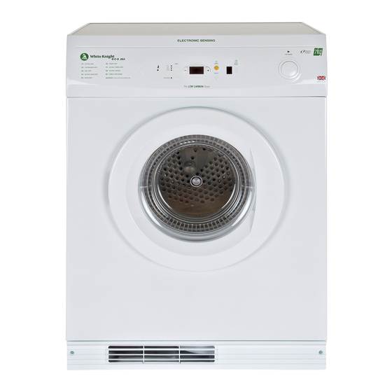
White Knight eco 86A Installation And Service Instructions Manual
The low carbon dryer
Hide thumbs
Also See for eco 86A:
- Instructions for use manual (13 pages) ,
- Instructions for use manual (13 pages)
Table of Contents
Advertisement
$)
Installation AND SERVICE INSTRUCTIONS
Keep this booklet for future reference.
The dryer must be fitted by a competent person. In the U.K. Registered Installers undertake to
work to safe and satisfactory standards.
The dryer must be installed in accordance with the Gas Safety (Installation and Use)
Regulations 2009.
Guidance may be obtained from the relevant parts of B.S. 7624: B.S. 5440 parts 1 and 2, B.S.
6891: current editions, I.E.E. Wiring Regulations, and relevant Building Regulations.
Failure to install the appliance correctly could invalidate the warranty liability claims and could
lead to prosecution.
FOR USE IN THE UNITED KINGDOM AND IRELAND WITH
NATURAL GAS ONLY I
, GAS SUPPLY PRESSURE : 20 mbar.
H
2
THE INSTALLER MUST LEAVE THIS BOOKLET WITH THE
CUSTOMER
Advertisement
Table of Contents

Summary of Contents for White Knight eco 86A
- Page 1 INSTALLATION AND SERVICE INSTRUCTIONS Keep this booklet for future reference. The dryer must be fitted by a competent person. In the U.K. Registered Installers undertake to work to safe and satisfactory standards. The dryer must be installed in accordance with the Gas Safety (Installation and Use) Regulations 2009.
- Page 2 Contents Technical Data Installation Service instructions Wiring diagram Exploded views Parts list WARNING THIS APPLIANCE SHALL BE INSTALLED IN ACCORDANCE WITH THE LOCAL REGULATIONS IN FORCE AND ONLY IN A WELL VENTILATED SPACE.READ THE INSTRUCTIONS BEFORE USING INSTALLING THIS APPLIANCE. THIS APPLIANCE CONFORMS TO THE FOLLOWING EEC DIRECTIVES.
-
Page 3: Technical Data
TECHNICAL DATA CONTROL Type:Pactrol full sequence flame control. Ignition electrode GENERAL gap to burner 3 to 4mm Flame failure electrode (4213 078 52641).Height from heater Front loading resistance sensing tumble dryer with gas base to centre of electrode 27.0±0.5mm. heating.Reverse action drum tumble.Electronic control. 2-temperature exhaust thermostat control.Induced air flow INLET THERMOSTAT enters dryer through front grille, some passes through the... - Page 4 INSTALLATION 5 POSITION OF DRYER AND CONNECTIONS 1INSTALLATION The dryer is designed for installation using a flexible gas connection with tubing in accordance with B.S.669. Ensure that the supply gas sizing is adequate. When installing, position the appliance so that the plug is accessible.
- Page 5 6. OPERATIONAL CHECK 9 STACKING 6.1 Remove the pressure test point screw from the gas Instructions for stacking, if required, are supplied tee connection at the back of the dryer and connect with the stacking kit. a gas pressure gauge. 6.2 Check that the dryer control is in the 'off' position, and PROGRAMME that the heat switch is set to 'high'.
- Page 6 SERVICE INSTRUCTIONS RECOMMENDATIONS FOR DISMANTLING Note:Re-assembly should be done in reverse sequence to these instructions. Terminal Block (28),Control Unit (10),Button Assy (352), Heat Switch, Micro-Switch Assembly (248),Control Panel (353). Withdraw 3 screws from the back flange of the Table Top Assy.(386) and lift and move it rearwards for removal.
- Page 7 Withdraw the 3-screws and shakeproof washers (13) Withdraw the 8-screws securing the Back Panel (24) to securing the Flame Tube Assy.(34) to the Cabinet Base. the Cabinet (196).Disengage the T-piece Grommet from Note:On re-assembly the shakeproof washers must be the slot in the Back Panel and lift off. replaced to ensure a good earth connection.
- Page 10 ECO 86A EXPLODED VIEW 1 10 or 10/1 203a...
- Page 11 ECO 86A_ Exploded View 2...
- Page 12 ECO 86A_ EXPLODED VIEW 3...
- Page 13 ECO 86A Exploded View 4 " % "! "...
- Page 14 ECO 86A Exploded View 5 Exploded View 5/1 - Heater Assembly 45/1...
- Page 15 Item Description Part Number Expl. View Control Unit identified on the control box 4213 078 54801 - use wiring diagram A 4213 092 25451 Control Unit identified on the control box 4213 078 57871 - 10/1 use wiring diagram B 4213 092 64561 Control Unit Bracket Assembly 4213 070 08623...
- Page 16 248 Door Microswitch Assembly 4213 092 05251 249 Gas Control Relay - only used with control box 092 25451 4213 092 51871 250 Exhaust Thermostat 50 Deg C 4213 078 49453 266 Drum Assembly 4213 092 44071 270 Drum Shaft/Bearing Kit 4213 092 05591 Button &...
- Page 17 454 Filter 4213 092 17821 455 Screw 6 x 12 2522 166 30001 456 Banjo Seal 4213 077 07992 458 Banjo Insert No 2 4213 077 53502 459 Banjo Insert No 1 4213 077 53492 463 Location Grommet 4213 077 07711 464 Slip Ring Insulator 4213 077 41253 465 Slip Ring...
- Page 20 Manufactured By: Crosslee plc, Halifax Road, Halifax, W. Yorks. HX3 8DE 4213 194 05463...


Need help?
Do you have a question about the eco 86A and is the answer not in the manual?
Questions and answers