
Related Manuals for Aquasafe 15201 SERIES

Summary of Contents for Aquasafe 15201 SERIES
- Page 1 INSTALLATION MANUAL & OWNER’S GUIDE WATER TREATMENT SYSTEMS 15201 SERIES 15203 SERIES REVERSE OSMOSIS MECHANICAL FILTRATION 15202 SERIES ULTRAVIOLET LIGHT WITH MECHANICAL FILTRATION...
-
Page 2: System Description
INTRODUCTION SYSTEM DESCRIPTION The Aquasafe™ Expandable Modular Water Treatment b. Recovery Rate: The systems are available with System consists of patented individual, self-contained, a 25% or 50% Recovery Rating. ready-to-install module assemblies. The module NOTE: The Recovery Rating specifies the assemblies may be installed as stand-alone units or percentage of influent water that is delivered as interconnected to form a complete, multi-phase system. - Page 3 INTRODUCTION BASIC SYSTEM CONFIGURATIONS REVERSE OSMOSIS SYSTEMS MODULES FILTER MODULE TYPES RINSE WATER FLOW MODEL OUTPUT NUMBER (GPD) TYPE SEDIMENT CARBON MEMBRANE 25% RECOVERY 50% RECOVERY 15201201 5 MICRON THIN FILM COMPOSITE 375 GPD 125 GPD 15201202 10 MICRON THIN FILM COMPOSITE 375 GPD 125 GPD 15201203...
- Page 4 Replacement of the reverse osmosis membrane, carbon cartridge, or ultraviolet lamp should be with one of identical specifications, as defined by WaterGroup to assure the same efficiency of operation. We strongly recommend that the system user test the product water at regular intervals (six months minimum) to make sure that the system is operating satisfactorily.
-
Page 5: Installation Requirements
INTRODUCTION INSTALLATION REQUIREMENTS CAUTION: Follow the directions in this Guide when installing your system to ensure that it operates correctly. CAUTION: The Aquasafe Water Treatment Systems are designed for indoor use only. LOCATION HARDWARE 1. A Module may be mounted on any vertical surface 1. -
Page 6: Installation
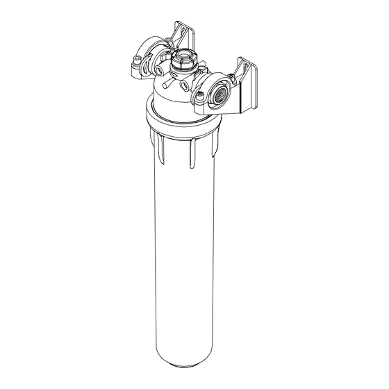
MECHANICAL FILTRATION AND REVERSE OSMOSIS MODULES INSTALLATION AND CONNECTION PROCEDURES The system must be installed in accordance with applicable city, state, and local plumbing codes. AquaSafe™ is designed to provide years of trouble-free service if properly maintained. Retain these instructions for future reference. MECHANICAL FILTRATION MODULE PREPARATION NOTE: Use thread sealing tape (P/N 35700002) on... - Page 7 MECHANICAL FILTRATION AND REVERSE OSMOSIS MODULES INSTALLATION AND CONNECTION PROCEDURES 5. CAUTION: Hold the membrane firmly to prevent it 7. CAUTION: Do not alter the length of the flow from rotating when the elbow is installed control tubing. To do so will change the system recovery rating.
- Page 8 MECHANICAL FILTRATION AND REVERSE OSMOSIS MODULES INSTALLATION AND CONNECTION PROCEDURES Item Description Part No. Item Description Part No. Valve, Solenoid 34800041 Sump Nipple, 3/4” 33601004 Filter or Membrane #13 33801110 Connector, Inlet/Outlet 1/2” FPT 21202012 Filter or Membrane #21 33801111 Connector, Inlet/Outlet 3/4”...
- Page 9 REVERSE OSMOSIS MODULE SUPPORT COMPONENT INSTALLATION PROCEDURE ELECTRONIC CONTROL BOX 3. CAUTION: Wiring connections must be secure to ensure the system operates properly. WARNING: DO NOT USE AN EXTENSION CORD TO To connect a wire to the terminal: RUN ELECTRICAL POWER TO THE SYSTEM. a.
- Page 10 REVERSE OSMOSIS MODULE SUPPORT COMPONENT INSTALLATION PROCEDURE CAUTION: The P/T LOCKOUT and TANK LEVEL WARNING: USE FDA APPROVED SILICONE SHUT-OFF connections require dry contacts. The LUBRICANT ON “O” RINGS. DO NOT USE terminal strip accepts dry contact switch signals capable PETROLEUM-BASED LUBRICANTS.
- Page 11 MECHANICAL FILTRATION OR REVERSE OSMOSIS MODULE CLEANING, SANITIZING AND FILTER REPLACEMENT PROCEDURE RECOMMENDATIONS HAVE ALL COMPONENTS ON HAND AND READY BEFORE BEGINNING PROCEDURE A CLEAN WORK AREA AND EQUIPMENT ARE ESSENTIAL TO PROPERLY CLEAN AND/OR DISINFECT THE SYSTEM (i.e., CLEAN HANDS, TOOLS, WORK SURFACE, AND CONTAINERS) EQUIPMENT NEEDED Liquid Dish Soap Safety Glasses...
- Page 12 MECHANICAL FILTRATION OR REVERSE OSMOSIS MODULE CLEANING, SANITIZING AND FILTER REPLACEMENT PROCEDURE 13. Slowly open source water supply valve. 20. Turn feed water valve slowly to open position. 14. Open outlet valve. Close valve as soon as water 21. Confirm system is producing water. Unit will be begins to flow from port.
-
Page 13: Cleaning Procedure
ATMOSPHERIC PRODUCT WATER STORAGE TANK CLEANING AND SANITIZING PROCEDURE RECOMMENDATIONS HAVE ALL COMPONENTS ON HAND AND READY BEFORE BEGINNING PROCEDURE A CLEAN WORK AREA AND EQUIPMENT ARE ESSENTIAL TO PROPERLY CLEAN AND/OR DISINFECT THE SYSTEM (i.e., CLEAN HANDS, TOOLS, WORK SURFACE, AND CONTAINERS) EQUIPMENT NEEDED Safety Glasses Liquid Dish Soap... - Page 14 ULTRAVIOLET MODULE INSTALLATION AND CONNECTION PROCEDURE WARNING: NEVER LOOK DIRECTLY AT A LIGHTED UV LAMP. ULTRAVIOLET RAYS CAN BE HARMFUL TO EYES. NEVER INSTALL SYSTEM UPSTREAM FROM PUMP. ASSEMBLY IS REQUIRED BEFORE CONNECTION. FOLLOW INSTRUCTIONS CAREFULLY! ULTRAVIOLET LAMP MODULE 3. Insert the Quartz Sleeve (Item 4) into the manifold head from the bottom.
- Page 15 ULTRAVIOLET MODULE INSTALLATION AND CONNECTION PROCEDURE Item Description Part No. Sump, Ultraviolet Lamp or Filter Cartridge #13 33801110 Sump, Ultraviolet Lamp or Filter Cartridge #21 33801111 “O” Ring, Sump 34202035 Channeling Device with Gasket #13 44301017 Channeling Device with Gasket #21 44301018 Gasket, Channeling Device 36099205...
- Page 16 ULTRAVIOLET MODULE INSTALLATION AND CONNECTION PROCEDURE AquaSafe™ Ultraviolet System AquaSafe™ Ultraviolet and Mechanical Filtration System 1 Module Unit, 4.5 or 8.5 GPM 2 Module Unit, 4.5 or 8.5 GPM with UV Lamp and Stainless Steel Sleeve with Sediment Filter and UV Lamp AquaSafe™...
- Page 17 ULTRAVIOLET MODULE OPERATIONAL REQUIREMENTS It is important that any water treatment system be properly maintained to ensure consistent water quality. Information provided on this page is of a general nature. For more detailed information, refer to the Cleaning, Disinfecting, and Filter Replacement Procedure on Page 14, the Mounting Bracket/Plumbing Installation Instructions (Pages 1 and 2), and Installation Instructions for the appropriate system (Page 2 for Mechanical Filtration and RO, Page 10 for UV Lamp).
- Page 18 ULTRAVIOLET MODULE CLEANING, SANITIZING, AND CARTRIDGE REPLACEMENT PROCEDURE RECOMMENDATIONS HAVE ALL COMPONENTS ON HAND AND READY BEFORE BEGINNING PROCEDURE A CLEAN WORK AREA AND EQUIPMENT ARE ESSENTIAL TO PROPERLY CLEAN AND/OR DISINFECT THE SYSTEM (i.e., CLEAN HANDS, TOOLS, WORK SURFACE, AND CONTAINERS) EQUIPMENT NEEDED Safety Glasses Liquid Dish Soap...
-
Page 19: Filter Replacement Procedure
ULTRAVIOLET MODULE CLEANING, SANITIZING, AND CARTRIDGE REPLACEMENT PROCEDURE UV LAMP REPLACEMENT PROCEDURE 3. CAUTION: Use care when sanitizing UV head. Do not get the UV control module or connectors wet. CAUTION: Refer to individual System Assembly and CAUTION: Tighten sumps by hand only. Do not Activation Procedures to identify specific components use tools as they will over-tighten and may damage matching the descriptions shown in this procedure. -
Page 20: Limited Warranty
If the Aquasafe™ Drinking Water Treatment Module, System, or any warranted component thereof is found defective, WaterGroup, at its sole option, will repair or replace such Product or warranted component. You pay only freight for repaired or replaced parts from our factory and local dealer charges, including but not limited to labor charges, travel and transportation expenses, and handling fees.
Need help?
Do you have a question about the 15201 SERIES and is the answer not in the manual?
Questions and answers