Table of Contents
Advertisement
Advertisement
Table of Contents

Related Manuals for Climate Technology 43057


Summary of Contents for Climate Technology 43057
- Page 1 HEAT PUMP DIGITAL THERMOSTAT Model 43057 Owners Manual...
-
Page 2: Table Of Contents
Congratulations! Your new CTC thermostat will provide years of reliable service. Using this digital ther- mostat will provide more uniform comfort in your home through the seasons. Thank you for buying a Climate Technology product! Please read this manual for complete instructions on installing and operating your thermostat. -
Page 3: Important Information
INSTALLATION What You Need This thermostat includes two #8 slotted screws and two wall anchors for mounting. To install your thermostat, you should have the following tools and materials. • Slotted screwdriver(s) • Small Philips screwdriver •... -
Page 4: Wire Labeling
• If the hole in wall is larger than necessary for wires, seal the hole with insulating material so that no hot or cold air can enter the back of the thermostat from the wall. This air could cause a false thermostat reading. -
Page 5: Mount Wallplate
Mount Wallplate • Remove the wallplate from the thermostat by pressing the release tab on the bottom of the thermostat. See Figure 2. Figure 2 • Position wallplate on wall and pull existing wires through the large opening, then level for appearance. If the existing mounting holes from the old wallplate line up with the slots in the new wallplate, then use the exisitng holes. -
Page 6: Connect Wires And Mount Thermostat To Wallplate
• Set the System Switch to “off”, and the Fan Switch to “auto”. • On the back of the thermostat are the System Set-Up Switches. See Figure 5. If the heat pump system has an electric auxiliary system, then slide the #1 switch to HE position. If the heat pump system has a gas auxiliary system, then slide #1 switch to the HG position. -
Page 7: Thermostat Controls
• Insert the tabs on top of the thermostat body into the slots at the top of the wallplate. Press the bottom of the thermostat body into the snap on the bottom of the wallplate. (NOTE: Do not force the thermostat onto the wallplate, as the terminal pins may be damaged. -
Page 8: Switches And Buttons
In the On mode, the fan runs continuously regardless of system status. D Reset button - push the Reset button with the end of a paper clip to reset the thermostat and return to its previous settings. -
Page 9: Lcd Display
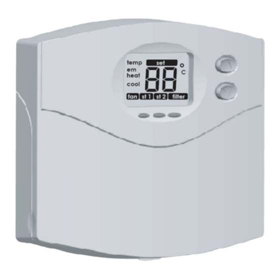
LCD Display LCD Display A temp - the large number being displayed is either the indoor temperature or the set temperature. B em - emergency heat is turned on. C heat - normal heat is turned on. D cool - normal cooling is turned on. E fan - indicates the fan is running. -
Page 10: Operation
The following Options are available on your thermostat: 1. 1st stage span - The factory setting for Stage 1 heating and cooling is 1, meaning that your thermostat will heat cycle at 1°F (0.5°C) above and below the set temperature in Stage 1. If the system is cycling too fast or heat “heat”... -
Page 11: Filter Reminder
The LCD Display will show “filter” after every 400 hours of fan operation, as a reminder to change the HVAC system’s filter as soon as possible. Resetting Your Thermostat Should the thermostat’s previous settings be desired, use the tip of a paper clip to press the “reset” button. NOTE: Pressing the Reset button reverts the thermostat to its previous settings, NOT the factory settings. -
Page 12: Wiring Diagram
Off position Thermostat permanently 1. Replace thermostat. reads “HI”, “LO” or “E1” after pressing the Reset button If you experience any other problems with your CTC thermostat, call CTC Technical Support at 1-800-676-7861 from 8am to 5pm Central Time. WIRING DIAGRAM... - Page 13 Climate Technology Corp. 2500 FRISCO AVENUE MEMPHIS, TN 38114 A Hunter Fan Company © 2006, Climate Technoogy Corp. Form No. 41982-01, 03/31/06...
Need help?
Do you have a question about the 43057 and is the answer not in the manual?
Questions and answers
Thermostat is stuck on em & aux