Table of Contents
Advertisement
Quick Links
Download this manual
See also:
Setup Manual
Extron Electronics, USA
Extron Electronics, Europe
1230 South Lewis Street
Beeldschermweg 6C
Anaheim, CA 92805
3821 AH Amersfoort
USA
The Netherlands
714.491.1500
+31.33.453.4040
www.extron.com
Fax 714.491.1517
Fax +31.33.453.4050
© 2005 Extron Electronics. All rights reserved.
Extron Electronics, Asia
Extron Electronics, Japan
135 Joo Seng Road, #04-01
Kyodo Building
PM Industrial Building
16 Ichibancho
Singapore 368363
Chiyoda-ku, Tokyo 102-0082 Japan
+65.6383.4400
+81.3.3511.7655
Fax +65.6383.4664
Fax +81.3.3511.7656
User's Manual
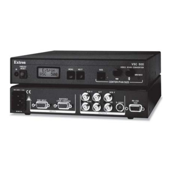
VSC 500/700/700D
Video Scan Converter
68-633-01 Rev. C
04 05
Advertisement
Table of Contents

Related Manuals for Extron electronics VSC 500


Summary of Contents for Extron electronics VSC 500
- Page 1 3821 AH Amersfoort PM Industrial Building 16 Ichibancho The Netherlands Singapore 368363 Chiyoda-ku, Tokyo 102-0082 Japan 68-633-01 Rev. C 714.491.1500 +31.33.453.4040 +65.6383.4400 +81.3.3511.7655 04 05 www.extron.com Fax 714.491.1517 Fax +31.33.453.4050 Fax +65.6383.4664 Fax +81.3.3511.7656 © 2005 Extron Electronics. All rights reserved.
- Page 2 Precaucion evitar riesgo de electrocución, no intentar personalmente la reparación/ particular use. In no event will Extron Electronics be liable for direct, indirect, or mantenimiento de este equipo, ya que al abrir o extraer las tapas puede quedar Leer las instrucciones • Leer y analizar todas las instrucciones de expuesto a voltajes peligrosos u otros riesgos.
- Page 3 Quick Start Guide — VSC 500/700/700D CAUTION Installation and service must be performed by authorized personnel only. These units must be installed in accordance with national and local electrical codes. To install the VSC 500/700/ Extron 700D, follow these steps and...
-
Page 4: Table Of Contents
Table of Contents Quick Start Guide — VSC 500/700/700D, cont’d Step 5 Chapter 1 • Introduction ............1-1 Plug the VSC, and input and output devices into a grounded AC About the VSC 500/700/700D .......... 1-2 source, and turn on the input and output devices. - Page 5 ................. A-6 Accessories ................A-6 Firmware Upgrade Chip Installation ......A-7 Introduction About the VSC 500/700/700D All trademarks mentioned in this manual are the properties of their respective owners. Features 68-633-01 Rev. C 04 05 VSC 500/700/700D • Table of Contents...
-
Page 6: About The Vsc 500/700/700D
1600 x 1200 resolution and 100 kHz horizontal and 120 Hz vertical scan rates. Input — Via a 15-pin HD female VGA connector (VSC 500) and BNC connectors (VSC 700/700D). Outputs — Simultaneously outputs RGB or component video, Installation and Operation composite video, S-video, and SDI (VSC 700D). -
Page 7: Application Example
Installation and Operation Application Example The illustration below is one example of using the VSC 500. Extron VSC Remote Infrared Remote RS-232 Control B/ B- S- VID R/ R- False Front Panel Uses 2 Front Holes B IN Extron VSC 500... -
Page 8: Rear Panel Connectors And Cabling
(RGBHV, RGBS, RGsB) via these five female BNC INPUTS OUTPUTS connectors. Connect cables for the appropriate signal type, as 50/60 Hz shown here. H/HV H/HV Figure 2-1 — VSC 500 rear panel connectors RGBHV RGBS H/HV RGsB H/HV R/R-Y B/B-Y 100-240V 0.3A... -
Page 9: Genlock And Vertical Interval Switching
75 ohm Terminator H/HV H/HV S-VIDEO required. RS-232 INPUTS OUTPUTS GENLOCK /422 50/60 Hz To Scope To Scope Probe B Probe A VSC 500/700/700D • Installation & Operation VSC 500/700/700D • Installation & Operation... -
Page 10: Oscilloscope Displays
When the phases are aligned, the wave peaks on the bottom waveform should line up with those in the reference signal above it. Vectorscope screen during horizontal phase adjustment VSC 500/700/700D • Installation & Operation VSC 500/700/700D • Installation & Operation... -
Page 11: Optimizing The System
The Min/Max LED will light red whenever the minimum or maximum limit of an adjustment knob is reached. Press the Size button again to turn the size feature off. 2-10 VSC 500/700/700D • Installation & Operation VSC 500/700/700D • Installation & Operation 2-11... -
Page 12: Front Panel Features
Press the Next and Size buttons simultaneously for two seconds to enable/disable the front panel security lockout feature. When this feature is enabled, 2-12 VSC 500/700/700D • Installation & Operation VSC 500/700/700D • Installation & Operation 2-13... -
Page 13: Menus, Configuration, And Adjustments
MENU The main menus are as shown in the following flowcharts. The Exit main menus for the VSC 500, 700, and 700D are identical except NEXT MENU Menu for the additional genlocking menu for the VSC 700/700D. Use the Menu button to scroll between main menus. -
Page 14: Auto Imaging Menu (Auto Set)
Set NTSC pedestal on or off input • On • On • Black (default) • Off • Off • Bars [color bars] Figure 2-10 — Output configuration menu 2-16 VSC 500/700/700D • Installation & Operation VSC 500/700/700D • Installation & Operation 2-17... -
Page 15: Filters Menu (Filters)
Zoom menu (Zoom) Flicker control The following flowchart provides an overview of the Zoom • 4 levels (0 - 3) with a default of 1 menu. Figure 2-11 — VSC 500 Filters menu Filters MENU Output Config Zoom Hzm 0512... -
Page 16: Genlock Menu (Genlock)
Additional Functions In addition to the main menu system, there are several other functions that are featured by the VSC 500/700/700D. Image sizing, shifting, freezing, a unit reset function, and an executive mode to disable the front panel controls are also available. -
Page 17: Freeze Mode
(see note below). See Front Panel Features in this chapter. If freeze mode is enabled, pressing the Next button from the Auto Imaging main menu will disable freeze mode. 2-22 VSC 500/700/700D • Installation & Operation VSC 500/700/700D • Installation & Operation 2-23... -
Page 18: Troubleshooting
The color subcarrier phase (Sub Phase) In a genlocked might require readjustment. system, displayed color is incorrect. The image still does Call Extron's customer support hotline. not display correctly. 2-24 VSC 500/700/700D • Installation & Operation VSC 500/700/700D • Installation & Operation 2-25... -
Page 19: Vsc Infrared Remote Control
For a detailed description of the other VSC features and functions that are accessed by the remote control, see earlier sections of this chapter. 2-26 VSC 500/700/700D • Installation & Operation VSC 500/700/700D • Installation & Operation 2-27... -
Page 20: Chapter 3 • Serial Communication
Installation and Operation, cont’d VSC 500/700/700D Chapter Three Serial Communication RS-232 Programmer’s Guide Control Software for Windows Firmware Upgrade from the Extron Web Site 2-28 VSC 500/700/700D • Installation & Operation... -
Page 21: Rs-232 Programmer's Guide
Serial Communication The VSC 500/700/700D can be remotely controlled via a host Error responses computer or other device (such as a control system) attached to When the VSC receives a valid SIS command, it executes the the rear panel RS-232/422 connector. The control device (host) command and sends a response to the host device. - Page 22 Serial Communication, cont’d VSC 500/700/700D • Serial Communication VSC 500/700/700D • Serial Communication...
- Page 23 Serial Communication, cont’d VSC 500/700/700D • Serial Communication VSC 500/700/700D • Serial Communication...
-
Page 24: Control Software For Windows
To install the software on the hard drive. 1. Run SETUP.EXE from the floppy disk. Figure 3-1 — VSC 500 Control Program window 2. Follow the instructions that appear on the screen. By default the installation creates a C:\VSC500 directory, and it places two icons (VSC Control Pgm and VSC Help) into a group or folder named “Extron Electronic”. -
Page 25: Using The Help Program
Enter keys to select a button/function. A description and tips on using the program will appear on screen. Select “Update Firmware File” from the following window. The uploading of the firmware to the VSC 500/700/700D will take a few minutes. 3-10 VSC 500/700/700D •... -
Page 26: Appendix A • Reference Information
Serial Communication, cont’d VSC 500/700/700D The original factory-installed firmware is permanently available on the VSC 500/700/700D. If the attempted A ppendix A upload of new firmware fails for any reason, the VSC will automatically revert to the factory-installed firmware. Reference Information... -
Page 27: Specifications: Vsc 500
All nominal levels are at ±10%. Output type ........RGBHV, RGBS, RGsB Specifications are subject to change without notice. Standards ........NTSC 3.58, PAL Input level ........1.5 V to 5.0 Vp-p VSC 500/700/700D • Appendix VSC 500/700/700D • Appendix... -
Page 28: Specifications: Vsc 700/700D
Minimum/maximum levels ..0.0 V to 1.0 Vp-p (Depth excludes knobs.) Impedance ........75 ohms Product weight VSC 700 ......2.8 lbs (1.3 kg) Sync VSC 700D ......2.9 lbs (1.3 kg) Input type ........Autodetect RGBHV, RGBS, RGsB VSC 500/700/700D • Appendix VSC 500/700/700D • Appendix... -
Page 29: Included Parts
To prevent electric shock, always unplug the VSC video scan converter from the AC power source Included Parts before opening the enclosure. These items are included in each order for a VSC 500/700/700D: Remove the scan converter from the rack or furniture. Included... - Page 30 Pull the chip straight out of the socket, and set it aside. Align the slots of the new firmware chip with the angled corners of the socket in the same orientation as the old chip. VSC 500/700/700D • Appendix VSC 500/700/700D • Appendix...
- Page 31 Gently, but firmly, press the chip into place in the socket. Replace the top cover on the VSC, and fasten it with the screws that were removed in step 3. Rack/furniture mount the scan converter, and reconnect the AC power cord. A-10 VSC 500/700/700D • Appendix...
Need help?
Do you have a question about the VSC 500 and is the answer not in the manual?
Questions and answers