Table of Contents
Advertisement
Quick Links
CAUTION:
1.
Weight on this product should not exceed 250 lbs.
2.
Class H equipment: This equipment is for home
use only. It is not for commercial use.
2005, 12
This Product is Produced Exclusively by
2040 N. Alliance, Springfield, MO 65803
Customer Service Number
1 (800) 375-7520
www.staminaproducts.com
Owner's Manual
!
Exercise can present a health
risk. Consult a physician
before beginning any exercise
program with this equipment.
If you feel faint or dizzy,
immediately discontinue use
of this equipment. Serious
bodily injury can occur if this
equipment is not assembled
and used correctly. Serious
bodily injury can also occur if
all instructions are not
followed. Keep others and
pets away from equipment
when in use. Always make
sure all bolts and nuts are
tightened prior to each use.
Follow all safety instructions in
this manual.
When calling for parts or
service, please specify the
following number.
STAMINA PRODUCTS
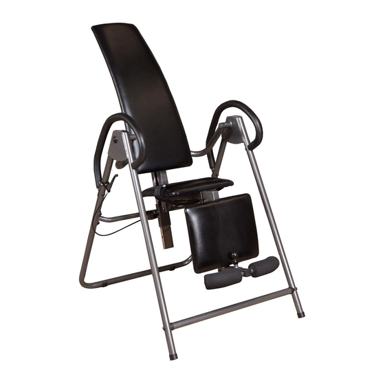
Product May Vary Slightly
2005 Stamina Products, Inc.
WARNING
!
55-1521
MADE IN CHINA
From Pictured.
Advertisement
Table of Contents

Related Manuals for Stamina 55-1521


Summary of Contents for Stamina 55-1521
- Page 1 Class H equipment: This equipment is for home use only. It is not for commercial use. Product May Vary Slightly From Pictured. This Product is Produced Exclusively by 2040 N. Alliance, Springfield, MO 65803 Customer Service Number 1 (800) 375-7520 www.staminaproducts.com 2005, 12 2005 Stamina Products, Inc.
-
Page 2: Table Of Contents
TABLE OF CONTENTS Page Page Safety Instructions Maintenance Instructions Before You Begin Product Parts Drawing Hardware Identification Chart Parts List Assembly Instructions Warranty Operational Instructions Notes Storage Fax/Mail Ordering Form SAFETY INSTRUCTIONS WARNING: To reduce the risk of serious injury, read the following safety instructions before Seated Inversion System using the Read all warnings posted on the Seated Inversion System. - Page 3 CALL US FIRST THANK YOU FOR PURCHASING THE Seated Inversion System Simply follow the few assembly instructions set forth in this manual. Within a few minutes you will be getting your body into shape and on your way to achieving a happier and healthier lifestyle.
-
Page 4: Before You Begin
BEFORE YOU BEGIN Seated Inversion Although Stamina tries to manufacture its products Thank you for choosing the with the finest materials and uses the highest System. We take great pride in producing this standards of manufacturing, occasionally a part that quality product and hope it will provide many hours does not fit, is the incorrect size, or is otherwise of quality exercise to make you feel better, look better... -
Page 5: Hardware Identification Chart
HARDWARE IDENTIFICATION CHAT This chart is provided to help identify the hardware used in the assembly process. After unpacking the unit, open the hardware bag and make sure that you have the following items: 3/16" 1/4" 5/16" 3/8" 1/2" INCHES 100 110 120 130 140 150 MILLIMETERS length... -
Page 6: Assembly Instructions
ASSEMBLY INSTRUCTIONS Place all parts from the box in a cleared area and position them on the floor in front of you. Remove all packing materials from your area and place them back into the box. Do not dispose of the packing materials until assembly is completed. - Page 7 ASSEMBLY INSTRUCTIONS STEP 3 CROSSING FRAME(4) REAR FRAME(3) BUTTON HEAD BOLTS Attach the onto the with (M8 x 15mm)(51) ARC WASHERS(M8)(62). STEP 4 SLIDER SUPPORT(10) CROSSING FRAME(4) HEX BOLT Attach the onto the Bracket on the with (M10 x 90mm)(55), NYLOCK NUT(M10)(58), WASHER(M10)(61).
- Page 8 ASSEMBLY INSTRUCTIONS STEP 6: LEFT PIVOT ARM(6) LEFT FRONT FRAME(1) Insert the into the and secure with the LARGE WASHER(M8)(41) BUTTON HEAD BOLT(M8 x 15mm)(51). Repeat on other side. STEP 7: BACK FRAME(8) LEFT RIGHT PIVOT ARMS Place the between the Brackets of the (6, 7) BUTTON HEAD BOLTS(M8 x 60mm)(54), NYLOCK NUTS(M8)(57), and secure with...
- Page 9 ASSEMBLY INSTRUCTIONS STEP 10 SUPPORT PLATES(16) BACK FRAME(8) FLAT HEAD BOLTS(M6 x 50mm) Attach the onto the with (49), WASHERS(M6)(59), NYLOCK NUTS(M6)(56). NOTE: SUPPORT PLATE(16) FLAT HEAD BOLT(M6 x 50mm)(49), The lowest is attached with a no washer and nut needed. STEP 11 BACK FRAME(8) A, B, C,...
- Page 10 ASSEMBLY INSTRUCTIONS Securing Pad must face down BOTTOM VIEW STEP 12 BELT GUIDES(21) SEAT CUSHION(18) Refer to the Bottom View in the illustration. Attach the onto the BUTTON HEAD BOLTS(M8 x 15mm)(51) WASHERS(M8)(60). with Make the Securing Pad face SEAT BELT(20) BELT GUIDES(21) SEAT CUSHION(18).
- Page 11 ASSEMBLY INSTRUCTIONS STEP 15 SUPPORT PLATES(16) LEG SUPPORT FRAME(12) FLAT HEAD Attach the onto the with BOLTS(M6 x 50mm)(49), WASHERS(M6)(59), NYLOCK NUTS(M6)(56). STEP 16 LEG SUPPORT CUSHION(19) SUPPORT PLATES(16) BUTTON HEAD Attach the onto the with BOLTS(M8 x 15mm)(51) WASHERS(M8)(60). STEP 17 HANDRAIL(14) LEFT FRONT FRAME(1)
-
Page 12: Operational Instructions
OPERATIONAL INSTRUCTIONS GENERAL PRECAUTIONS Seated Inversion System Do not use the alone. Always have a helper available in case assistance is needed in recovering from the decline position. LEVER(30), CABLE(29), SPRING PIN(28). Check the Make sure the system works smoothly BEFORE Seated Inversion System. - Page 13 OPERATIONAL INSTRUCTIONS FOAM PAD USE AND ADJUSTMENT FOAM PADS(23) Place your feet under the with your ankles FOAM PADS(23) LEG SUPPORT between the and the CUSHION(19). BALL SPRING PIN(26) FOAM PAD Pull the and slide the SUPPORT(13) toward you until your ankles are properly held FOAM PADS(23) LEG SUPPORT between the...
- Page 14 OPERATIONAL INSTRUCTIONS USING THE SEATED INVERSION SYSTEM Start by sitting on the machine and leaning back on the back cushion with your hands at your side, or resting on your thighs. Pull and hold the LEVER(30) with your right hand. Use the handrail and your left hand to rotate the BACK CUSHION(17) slowly backward.
-
Page 15: Storage
Worn or damaged components shall be replaced immediately or the removed from service until repair is made. Seated Inversion Only Stamina Products supplied components shall be used to maintain/repair the System. Seated Inversion System Keep your clean by wiping with an absorbent cloth after use. -
Page 16: Product Parts Drawing
PRODUCT PARTS DRAWING BACK FRONT... -
Page 17: Parts List
PARTS LIST DIAGRAM# PART NAME Left Front Frame Right Front Frame Rear Frame Crossing Frame Connecting Bar Left Pivot Arm Right Pivot Arm Back Frame Back Support Bar Slider Support Seat Frame Leg Support Frame Foam Support Handrail Foam Grip Support Plate Back Cushion Seat Cushion... - Page 18 PARTS LIST DIAGRAM# PART NAME Rectangular Plug (23.5mm x 53.5mm) Bolt, Round Head (M6 x 1 x 20mm) Bolt, Flat Head (M6 x 1 x 50mm) Bolt, Button Head (M6 x 1 x 47mm) Bolt, Button Head (M8 x 1.25 x 15mm) Bolt, Button Head (M8 x 1.25 x 45mm) Bolt, Button Head (M8 x 1.25 x 50mm) Bolt, Button Head (M8 x 1.25 x 60mm)
-
Page 19: Warranty
To implement this limited warranty, send a written notice stating your name, date, and place of purchase and a brief description of the defect along with your receipt to Stamina Products, Inc. P.O. Box 1071, Springfield Missouri, USA, 65801-1071 or call us at 1 (800) 375-7520. If the defect is covered under this limited warranty, you will be requested to return the product or part to us for free repair or replacement at our option. -
Page 20: Notes
NOTES... - Page 21 NOTES...
-
Page 22: Fax/Mail Ordering Form
(417) 889-8064. Our Customer Service Department will be able to assist you with your problem and the part will be mailed directly to your house. MAIL TELEPHONE ONLINE STAMINA PRODUCTS, INC. CUSTOMER SERVICE CUSTOMER SERVICE CUSTOMER SERVICE ATTN: Customer Service...
Need help?
Do you have a question about the 55-1521 and is the answer not in the manual?
Questions and answers