Table of Contents
Advertisement
SINCE 1932
SINCE 1932
SINCE 1932
SINCE 1932
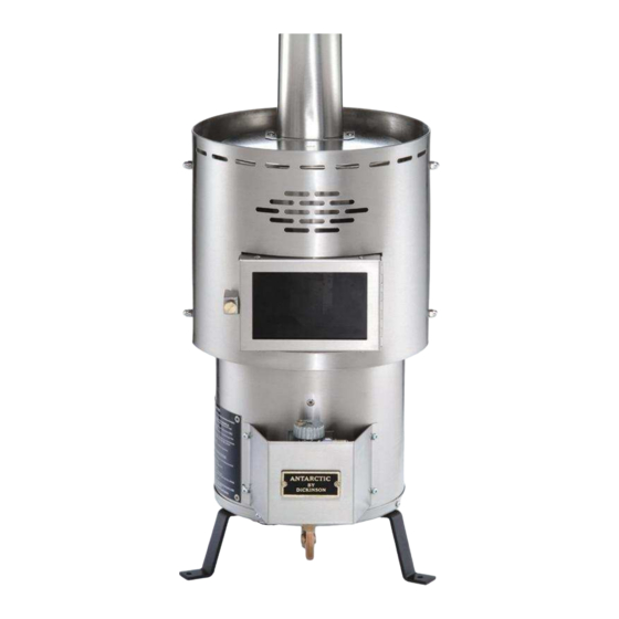
Antarctic Diesel
Operator's Manual
This manual must be read and the requirements carried out
to ensure satisfactory performance.
DICKINSON RESERVES THE RIGHT TO MAKE CHANGES TO PRODUCTS
QUALITY INSPECTED BY-
Heater
OR DOCUMENTS AT ANY TIME
Doug & Don
Dickinson Marine
#407-204 Cayer St Coquitlam
BC Canada V3K 5B1
www.dickinsonmarine.com
info@dickinsonmarine.com
T: 800 659 9768
F: 604 525 6417
Jul 15/2008
DATE-
Advertisement
Table of Contents

Related Manuals for Dickinson Antarctic Diesel


Summary of Contents for Dickinson Antarctic Diesel
- Page 1 Antarctic Diesel Heater Operator’s Manual This manual must be read and the requirements carried out to ensure satisfactory performance. DICKINSON RESERVES THE RIGHT TO MAKE CHANGES TO PRODUCTS OR DOCUMENTS AT ANY TIME Doug & Don Jul 15/2008 QUALITY INSPECTED BY-...
-
Page 2: Table Of Contents
CONTENTS Warnings and Disclosures pg-2 Burner Assembly pg-17 Installation Diagram pg-3 Burner Diagram pg-18 Clearance Diagram pg-4 Combustion Air pg-18 Location pg-4 Draft Assist Fan pg-19 Mounting and Securing pg-5 Checklist pg-20 Flue Stack (chimney) pg-6 Lighting Instructions pg-21 Barometric Install pg-6 Operating tips pg-23... -
Page 3: Warnings And Disclosures
Warnings and Disclosures - Follow all installation and operating procedures. - The oil heater requires an installed flue for correct operation. Do not attempt to operate the heater without the flue chimney installed correctly as required in this manual. - A permanently open fresh air inlet vent must be installed near the heater to provide air to the heater for combustion. -
Page 4: Installation Diagram
Installation Diagram NOTE: Not all installations will require a pump, gravity tank, elbows, or coil options... -
Page 5: Clearance Diagram
Clearance Diagram Installation Guidelines Location The location of the heater must be large enough to provide safety clearances. Objects and materials closer to the heater than 6” must be lined with high density, heat retardant insulation and covered with metal (stainless steel, aluminum, etc.). Another alternative is using ceramic tiles. -
Page 6: Mounting And Securing
Ideally, the heater should face the bow or stern of your vessel, particularly on a sailboat. Fuel gravity feeds from the oil-metering valve into the burner. Should this valve drop below the level of the burner fuel will not flow uphill into the burner and the fire will go out. -
Page 7: Flue Stack (Chimney
Flue Stack The length and straightness of the flue stack are important to the efficient operation of the heater. The Flue stack must be the correct diameter. If elbows must be used, the elbows shall not be greater than a 45 degree angle. The first elbow should not be closer than 12” (28cm) to the heater. -
Page 8: Fuel Supply
A hole through the center of the block would be 2 inches greater in diameter than the flue pipe. The Dickinson DP or H style flue caps are recommended. The location of the flue cap above deck must be clear of any immediate obstruction that may cause unusual air movement or turbulence. - Page 9 # 20-002, or call / email Dickinson for retrofitting a stronger pressure spring in your pump and installing a pressure regulator # 20-003 between the pump and the valve (converting a #20-000 FRD-2 pump to a #20-002 FRD-HD pump.
- Page 10 -8A- installed as per diagram. Place the check valve as shown in the diagram on top of the heavier replacement spring, and the spring on top of the pump plunger and push it back into the pump body holding it in with a finger. Note the magnetic part of the plunger is on the opposite end of the spring.
- Page 11 -8B- #20-002 FRD-HD c/w REGULATOR We recommend using an elbow fitting on the fuel inlet. When priming this pump hold down the knob of the pressure regulator to prime the fuel lines and take out the air then turn the dial to the lowest setting on the regulator and increase pressure 1 increment at a time until the pump is just delivering a small amount of fuel as the heater/stove only requires a very small amount .
-
Page 12: Fuel Overflow
A fuel shut off valve must be installed as a positive shut off control for the fuel supply. We suggest this be installed in the same area that the heater is being used. Dickinson can provide a fuel filter/shut off valve#20-010 with a replaceable stone element #20-020. - Page 13 -10-...
-
Page 14: Fuel Variations
-11- Fuel Variations It is unlikely that the fuel you are using is the same viscosity as the fuel used to calibrate the oil-metering valve. Diesel is one of the few fuels you can reliably get all around the world but the quality and viscosity of that fuel is variable. Fuel differs on a routine basis even though you buy the same oil from the same supplier. -
Page 15: Valve Diagram
-12- Fuel Flow Measurement If your heater is burning rich (making soot or smoking) or burning lean (flames not burning above the top burner ring), adjust the flow as follows regardless of what type of fuel: 1) Unscrew the compression nut from the bottom of the valve and bend away the copper fuel line. - Page 16 -13-...
- Page 17 -14- Oil Metering Valve #02-200 - Information & Rebuild Instructions Do not plug the overflow fitting. A fuel line must be taken from the overflow fitting and returned to the main tanks or to a vented container. The overflow line is a gravity escape and must be installed in such a manner as to prevent air locks.
-
Page 18: Valve Rebuild
Your kit has been packed with all the parts to rebuild your valve. The parts may differ in detail from what you have in your valve. This is due to changes and to the unavailability to the parts over the decades. These parts provided in this kit will work in any Dickinson Valve. - Page 19 -16- • Insert the float hinge pin and test the movement of the float up and down and that it moves the needle up and down in the fitting. (When held upside-down, the bottom of the float should be parallel to the casting of the valve, in both directions).
-
Page 20: Valve Safety Features
In case of the release of the fusible link, a replacement part is available from Dickinson or just remove the brass nut (do not move the adjusting screw) and apply heat from a lighter to re-solder the link back into its original position (flat on the top). -
Page 21: Combustion Air
-18- Combustion Air To guarantee that sufficient oxygen (fresh air) is available for your heater, good ventilation is essential. It is necessary to replace the air inside your boat at the same rate that the heater is removing it. The higher the heater’s burning rate, the more air the heater will require. If the air flow is blocked (the ‘draft’) or restricted, the heater will burn inefficiently, create soot or even blow out. -
Page 22: Draft Assist Fan
A CO alarm should be installed in the boat along with the Dickinson high heat shut-off #02-210, if you are unable to fully attend the stove and still be on board the boat. -
Page 23: Checklist
-20- Installation Check-List for a Natural Draft Oil Heater / Stove A permanent 3” dia. fresh air vent to provide your heater/stove with the air it needs to operate properly. Have a minimum of 4 feet of exhaust stack. The first 12” of exhaust pipe from the heater/stove is going straight up without any elbows. -
Page 24: Lighting Instructions
-21- Lighting Instructions ENGAGE PUMP OR OPEN GRAVITY FEED VALVE TO ALLOW FUEL INTO THE METERING VALVE ON THE HEATER. OPEN THE DOOR AND REMOVE THE SUPERHEATER TURN THE OIL METERING VALVE ON UNTIL APPROX 30 ml (2 tblsp) OF OIL HAS COLLECTED IN THE BOTTOM OF THE BURNER POT TURN THE OIL METERING VALVE LIGHT THE POOL OF FUEL WITH A SMALL TWISTED PIECE OF TISSUE OR PAPER... - Page 25 -22- The first time the oil-metering valve is turned on it will take 5-10 minutes for the fuel lines to fill and oil to appear in the bottom of the burner. In the beginning you will want to see approximately 2 tablespoons of oil accumulate in the bottom of the pot before lighting.
-
Page 26: Operating Tips
-23- Operating Tips Every time the position of the knob on the oil metering valve is moved (fuel), the air will need adjusting in order to have the correct fuel to air mixture. This will: clean 1 Keep the burner, combustion chamber, flue pipe, and your deck 2 Keep the draft strong against down drafts 3 Keep the correct heat in the correct part of the combustion chamber On the lower settings the burner needs less air. -
Page 27: Flooding Burner
-24- Flooding Burner A vaporizing oil burner of this type can be flooded if care is not taken to prevent excess oil entering the burner when lighting. By following the lighting instructions flooding will be avoided. A flooded burner that is still burning should be turned off and the heater monitored until the oil has burned off. -
Page 28: Coil Install
-25- The coils in a heater can be used to heat the water in your existing hot water supply tank. If the tank is mounted above the lower coil the water will circulate on its own from the tank into the hot coils and rise back into the tank. If the 2 turn coil is used on smaller tanks, it will make the water too hot and the pressure/temperature relief valve will release too often. -
Page 29: Burner Replacement
-26- Cleaning Burner Carbon accumulates in the burner over a period of time and it must be cleaned out. It is especially important to ensure the air holes are clear. If you are burning good quality fuel and the heater is burning efficiently this cleaning procedure will only be required once a year. -
Page 30: Re-Cementing
-27- Cleaning Fuel Lines Any blockage in the fuel line from the oil-metering valve to the burner can be cleaned by removing the clean-out plug situated directly under the burner. The plug must be replaced with tape sealant and checked for leaks. The fuel lines themselves can be cleaned with compressed air or a pipe cleaner to remove any blockages. -
Page 31: Lighting Instructions
-28- DO NOT OPERATE THIS PRODUCT UNATTENDED Lighting Instructions 1. Remove top lid / open door 2. Turn the oil metering valve ON and allow about 30 ml (2 tbls) of fuel into the burner. 3. Turn the oil metering valve OFF 4. -
Page 32: Trouble Shooting
-29- Trouble Shooting - No fuel in the bottom of the burner Check the tank is vented or the pump has power and all shut-offs are open. Disconnect the fuel outlet on the bottom of the valve, and let the valve drip into a container to test if the fuel is getting into the valve. - Page 33 -29A-...
-
Page 34: Faq
-30- Can I burn bio diesel? yes, refer to page-14 in the manual Can I burn low carbon diesel? yes, same as bio-diesel, refer to page-14 Why is there hard carbon in the bottom of the burner? fuel burning with too much air, refer to page-12 & 30 Why is the window glass and combustion chamber sooty? fuel burning with not enough air, refer to page-12 &... -
Page 35: Limited Warranty
If any part of your new product fails because of a manufacturing defect within the warranty period Dickinson offers to replace said parts free of charge, provided, however, that such parts have not been improperly repaired, altered or tampered with or subjected to misuse, abuse or exposed to corrosive conditions. This warranty, however, is limited by certain exclusions, time limits and exceptions as listed below. -
Page 36: Warranty Form
-32- Return to: SINCE 1932 #407 – 204 Cayer Street, Coquitlam, B.C. Canada V3K 5B1 WARRANTY FORM I have read and understand the Limited Warranty and the Instruction Manual and agree to the terms and condition (please print) Date…………………………………………………………………………… Purchaser’s Name…………………………………………………………….. Address………………………………………………………………………..
Need help?
Do you have a question about the Antarctic Diesel and is the answer not in the manual?
Questions and answers