Table of Contents
Advertisement
Advertisement
Table of Contents

Related Manuals for Milltronics XRS-5


Summary of Contents for Milltronics XRS-5
- Page 1 XRS-5/XRS-5CTRANSDUCER Instruction Manual PL-590 January 2001 33455900 Rev. 2.0...
- Page 2 Contact SMPI Technical Publications at the following address: Technical Publications Siemens Milltronics Process Instruments Inc. 1954 Technology Drive, P.O. Box 4225 Peterborough, Ontario, Canada, K9J 7B1 Email: techpubs@milltronics.com For the library of SMPI instruction manuals, visit our Web site: www.milltronics.com © Siemens Milltronics Process Instruments Inc. 2001...
-
Page 3: Table Of Contents
Standpipes and Stilling Wells.............14 Water / Wastewater................15 Transducer Placement ..............16 Locations ..................16 Interconnection ..................19 Direct Connection ................19 Coaxial Connection ................20 2-Wire Extension (for EnviroRanger ERS 500 only)......20 Maintenance ..................20 Installation Diagram for XRS-5 ..............21 Installation Diagram for XRS-5C............22 PL-590 XRS-5 Transducer Page 3... - Page 4 Page 4 XRS-5 Transducer PL-590...
-
Page 5: Specifications
Operation: Beam Angle 10° Frequency 43 KHz Temperature Sensor internal Supply Source transducer shall only be supplied by Milltronics certified controller Environmental: Location indoor / outdoor Ambient temperatures -20 to 65 °C (-4 to 149 °F) Altitude 2000 m maximum... - Page 6 Page 6 XRS-5 Transducer PL-590...
-
Page 7: About The Transducer
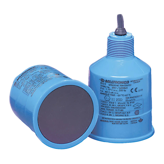
About the Transducer The Echomax XRS-5 transducer works with Milltronics transceivers and provides the ultrasonic pulse and echo reception that these devices require. The transducer converts electrical pulses transducer provided by the transceiver to ultrasonic pulses used for measurement and then converts the ultrasonic echoes back to an electrical signal. -
Page 8: General Guidelines
Kynar Flex 2800-02 (former designation 2820) / Chlorosulfonated polyethylene / Nitrile / Ethylene propylene / Chloroprene Encapsulant: LA-9823-76 • Manual override can be accomplished by using the disconnect switch provided in the building installation of the associated controller. Page 8 XRS-5 Transducer PL-590... -
Page 9: Installation
Flange (optional) 127mm 127mm (5.0”) (5.0”) ANSI, DIN or JIS 89mm standards (3.5”) Submergence Shield Split Flange (optional) 133mm (5.2”) nominal 155mm (6.1”) ANSI, DIN or JIS standards 124mm (4.9”) Refer to Milltronics instruction manual PL-530. PL-590 XRS-5 Transducer Page 9... - Page 10 Page 10 XRS-5 Transducer PL-590...
-
Page 11: Mounting
Submersible Plywood rigid metal conduit coupling coupling submergence shield Submersible transducer, used in Plywood mounting provides excellent applications where flooding is possible. isolation, but must be rigid enough to avoid flexing if subjected to loading. PL-590 XRS-5 Transducer Page 11... - Page 12 Note: Tighten the flange bolts evenly in order to ensure a good seal between the mating flanges. Caution: Over tightening can cause performance degradation. Page 12 XRS-5 Transducer PL-590...
-
Page 13: Applications
Refer to OCM manufacturer specification for proper point of head measurement. The OCM III requires the use of the TS-2 external temperature sensor instead of the XRS-5 internal temperature sensor. The use of an external temperature sensor provides better temperature tracking in applications where the temperature can change quickly. -
Page 14: Standpipes And Stilling Wells
Standpipes and Stilling Wells In many applications, access must be made via a standpipe. In such cases, Milltronics can provide factory flanged transducers or split flange kit that will readily mate to the flanged standpipe. Another option is to hang the transducer from a blind flange. -
Page 15: Water / Wastewater
Water / Wastewater Differential Level Pump Control Sewage Lift PL-590 XRS-5 Transducer Page 15... -
Page 16: Transducer Placement
Transducer Placement The following graphic shows the best placement of the XRS-5 transducer. ‘A’ ‘B’ ‘C’ Maintain full fluid level for full or offset calibration. Do not allow material to enter blanking zone. span: beam distance between angle Empty and Full... - Page 17 Beam should not detect bin bottom. If this occurs, use range extension parameters (on transceivers where available) to omit false echoes. The XRS-5 transducer operates with a beam angle of 10° and has a rise:run ratio of approximately 12:1. This means that for every 1m (3.3’) of tank height, the transducer projects a...
- Page 18 Page 18 XRS-5 Transducer PL-590...
-
Page 19: Interconnection
In all of the following examples the terminal blocks on the transceiver are described in the transceiver manual. Direct Connection Connect the transducer directly to the Milltronics transceiver via the 2 conductor shielded cable. drain / shield Note: When connecting to an EnviroRanger ERS 500, the white, black, and shield wires are all connected separately. -
Page 20: Coaxial Connection
Coaxial Connection Connect the transducer to the Milltronics transceiver via a junction box and RG–62 A/U coaxial cable. This setup is effective for combined runs up to 365m (1200’). extend cable using RG – 62 A/U coax Note: When connecting to an EnviroRanger ERS 500, do NOT use coaxial cable, see diagram below for proper procedure. -
Page 21: Installation Diagram For Xrs-5
Installation Diagram for XRS-5 PL-590 XRS-5 Transducer Page 21... -
Page 22: Installation Diagram For Xrs-5C
Installation Diagram for XRS-5C Page 22 XRS-5 Transducer PL-590... - Page 23 *7ml19981bj01*...
Need help?
Do you have a question about the XRS-5 and is the answer not in the manual?
Questions and answers