
Related Manuals for Hubbell Electric Heater Company MSE


Summary of Contents for Hubbell Electric Heater Company MSE
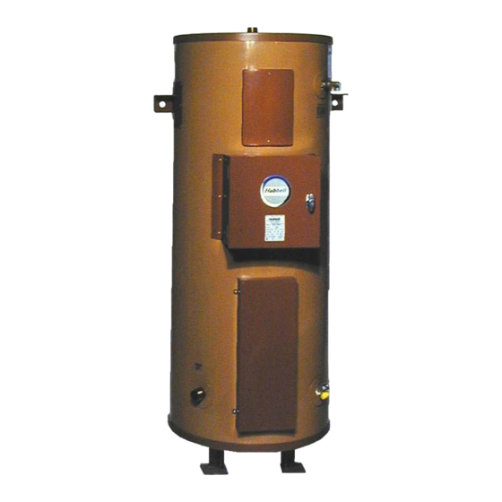
- Page 1 OPERATING AND MAINTENANCE MANUAL FOR MARINE ELECTRIC WATER HEATER ELECTRIC HEATER COMPANY BASE MODEL “ MSE ”...
-
Page 2: Warning / Caution
A qualified installer is a person who has licensed training and a working knowledge of the applicable codes regulation, tools, equipment, and methods necessary for safe installation of an electric resistance water heater. If questions regarding installation arise, check your local plumbing and electrical inspectors for proper procedures and codes. -
Page 3: Table Of Contents
SECTION TITLE GENERAL DESCRIPTION AND CONSTRUCTION INSTALLATION SCHEDULED MAINTENANCE AND OPERATION TROUBLESHOOTING SERVICING AND REPLACEMENT OF PARTS MISCELLANEOUS CHARTS AND FORMULAS ABS TYPE APPROVAL PROGRAM TABLE OF CONTENTS PAGE #... -
Page 5: Tank Connections
GENERAL DESCRIPTION AND CONSTRUCTION GENERAL DESCRIPTION This book describes a packaged electric water heater, approved by ABS Americas (A Division of the American Bureau of Shipping) and the USCG (United States Coast Guard), which is a stationary, self contained unit and is designed and constructed specifically for marine applications on board a surface vessel. -
Page 6: Control Thermostat
CONTROL THERMOSTAT The water heater is supplied with either a surface mounted or immersion thermostatic switch that is installed and wired at the factory. See drawing for specific details. The surface mounted thermostat can be adjusted through a range of 110° - 170° F. The immersion thermostat can be adjusted through a range of 100°... -
Page 7: Magnetic Contactor
The tank is encapsulated in 2-inch thick polyurethane foam insulation. The insulation is protected by a high impact non-corroding colorized composite protective jacket. OPTIONS The following optional features may be included in your water heater. Reference included drawing specific to your heater for further details. Low Water Cut-Off... - Page 8 Fused Low Voltage Transformer A fused low voltage transformer may be supplied. This option is used to step down higher voltages to 120-volt for the control circuit. Dial Temperature and Pressure Gauge A combination temperature (70° - 250° F) and pressure (0 – 200 psi) gauge with 2½-inch dial may be supplied for in-line installation (shipped loose) or factory installed in the tank.
- Page 9 On/Off Switch A built-in non-fused On/Off disconnect switch may be supplied with the control panel to disconnect power to the control panel control and power circuit wiring. Individually Fused Elements To prevent the possibility of damage to circuits and elements in case of electrical overloads, fuses may be supplied for each circuit.
-
Page 10: Water Heater Placement
1. Place the heater on a solid foundation in a clean, dry location nearest to the point of most frequent hot water use. 2. The water heater should be protected from freezing and waterlines insulated to reduce energy and water waste. - Page 11 Mounting Dimensions Tank Overall Diameter Diameter “A” “B” 18 3/4 22 3/4 Bolt Bulkhead Mounting Circle Dimension “C” “D” None None None Gallon Capacity...
-
Page 12: Piping Installation
PIPING INSTALLATION NOTE: The most effective means for preventing deterioration from accelerated corrosion due to galvanic and stray current is the installation of dielectric fittings/unions. The installation of these fittings is the responsibility of the installing contractor. 1. Connect the cold water inlet and hot water outlet to the appropriate connections as shown; refer to the drawing for location and sizes. -
Page 13: Electrical Installation
ELECTRICAL INSTALLATION 1. Enter electric enclosure with properly sized feeder leads. Be sure to properly ground the water heater. 2. Install these power leads into the box lugs on the terminal block or magnetic contactor. 3. Torque screws per torque chart included in Section VI. -
Page 14: Scheduled Maintenance And Operation
MAINTENANCE AND OPERATION The water heater is automatic in its operation. It will maintain a full tank of water at the temperature setting of the thermostat. The water heater should not be turned on without first making sure that the tank is full of water and that all air has been released. -
Page 15: Annual Inspection
ANNUAL INSPECTION 1. Flush tank as follows a. Shut off power supply. b. Close valve on hot water outlet piping. c. Open valve on drain piping. d. Cold water inlet line pressure will be strong enough to flush sediment from the bottom of the tank out through the drain. -
Page 16: Troubleshooting
SECTION IV – Symptom No hot water TROUBLESHOOTING Probable Cause Circuit breaker tripped at source. On/Off switch in ‘OFF’ position, if installed. Circuit breaker at control cabinet tripped, if installed. Blown fuse in element fuse block, if installed. Blown fuse in transformer, if installed. - Page 17 Water temperature below settings at all times Relief valve discharges continuously Faulty thermostat. Blown fuse in element fuse block, if installed. Heating element not working on all phases Heater improperly sized Excessive temperature or pressure in tank Check thermostat adjustment. Monitor thermostat as described in Section III, Quarterly Inspection.
-
Page 18: Vservicing And Replacement Of Parts
SECTION V - Before servicing or replacing any part make sure to turn the power supply switch to the OFF position. SURFACE TEMPERATURE HIGH LIMIT CUT-OFF 1. Disconnect power from unit. 2. Remove access cover. 3. Disconnect the four (4) 14 gauge wires. Control Wires 4. - Page 19 IMMERSION TEMPERATURE HIGH LIMIT CUT-OFF 1. Disconnect power from unit. 2. Remove access cover. 3. Remove high limit cover screw and cover. 4. Disconnect the two (2) 14 gauge wires. Wires 5. Remove capillary tube and bulb from thermowell 6. Remove two (2) mounting screws. 7.
- Page 20 HEATING ELEMENT 1. Disconnect power from unit. 2. Shut off incoming water supply. 3. Attach hose to drain connection. 4. Lift manual release lever on relief valve to let air into system or break union on outgoing water line. 5. Drain water from tank. 6.
- Page 22 SURFACE MOUNTED THERMOSTAT 1. Disconnect power from unit. 2. Remove access cover and locate thermostat. 3. Disconnect the two (2) 14 gauge wires. Control Wires 4. Remove two (2) mounting screws. Mounting Screws 5. Replace thermostat using the reverse procedure.
-
Page 23: Immersion Thermostat
IMMERSION THERMOSTAT 1. Disconnect power from unit. 2. Remove access cover and locate thermostat. 3. Remove high limit cover screw and cover. 4. Disconnect the two (2) 14 gauge wires. 5. Remove capillary tube and bulb from thermowell. 6. Remove two (2) mounting screws. 7. - Page 24 MAGNETIC CONTACTOR 1. Disconnect power from unit. 2. Disconnect line and load wires to contactor. 3. Disconnect two (2) 14 gauge control circuit wires. 4. Loosen two (2) holding screws and remove contactor. 5. Replace with new contactor using reverse procedure. Control Wires Line Wires Load Wires...
-
Page 25: Relief Valve
RELIEF VALVE 1. Disconnect power from unit. 2. Shut off incoming water supply. 3. Lift test lever on relief valve to relieve pressure in tank. 4. Disconnect overflow piping. 5. Unscrew relief valve, remove assembly and replace with new one. 6. -
Page 26: Miscellaneous Charts And Formulas
SECTION VI – ELEMENT CHART Immersion Element Length Part # 2-38683N 13" 3-38683N 13" 4-38683N 13" 5-38683N 13" 6-38683N 13" 7-38683N 13" 8-38683N 13" 9-38683N 15" 10-38683N 15" 11-38683N 15" FORMULAS MISCELLANEOUS CHARTS AND FORMULAS Resistance (Ohms) 1 Φ 3 Φ DELTA Hairpin 57.6 19.2... -
Page 27: Torque Values
TORQUE VALUES 18-8 S/S BRASS BOLT SIZE IN.-LBS. IN.-LBS. 4-40 4-48 5-40 5-44 6-32 6-40 12.1 8-32 19.8 8-36 22.0 10-24 22.8 10-32 31.7 1/4-20 75.2 1/4-28 94.0 5/16-18 5/16-24 3/8-16 3/8-24 7/16-14 7/16-20 1/2-13 1/2-20 9/16-12 9/16-18 5/8-11 1110 5/8-18 1244 3/4-10... -
Page 28: Abs Type Approval Program
SECTION VII – ABS TYPE APPROVAL PROGRAM...
Need help?
Do you have a question about the MSE and is the answer not in the manual?
Questions and answers