
Related Manuals for JAI SP-5000M-PMCL


Summary of Contents for JAI SP-5000M-PMCL
- Page 1 Spark Series User Manual SP-5000M-PMCL SP-5000C-PMCL 5M CMOS Digital Progressive Scan Monochrome and Color Camera Document Version: Ver.1.1 SP-5000-PMCL_Ver.1.1_Oct2013 1046E-1305...
- Page 2 JAI Ltd., Japan and may only be used by the purchasers of the product. JAI Ltd., Japan makes no warranty for the use of its product and assumes no responsibility for any errors which may appear or for damages resulting from the use of the information contained herein.
- Page 3 SP-5000M-PMCL Supplement The following statement is related to the regulation on “ Measures for the Administration of the control of Pollution by Electronic Information Products “ , known as “ China RoHS “. The table shows contained Hazardous Substances in this camera.
- Page 4 SP-5000C-PMCL Supplement The following statement is related to the regulation on “ Measures for the Administration of the control of Pollution by Electronic Information Products “ , known as “ China RoHS “. The table shows contained Hazardous Substances in this camera. mark shows that the environment-friendly use period of contained Hazardous Substances is 15 years.
-
Page 5: Table Of Contents
SP-5000M-PMCL / SP-5000C-PMCL Contents Before using this camera ..............- 6 - General ...................- 7 - Camera composition ..............- 7 - 3. Key features ................- 8 - 4. Parts locations and their functions ...........- 9 - 4.1 Parts locations and their functions ............... - 9 - Rear Panel .................... - Page 6 SP-5000M-PMCL / SP-5000C-PMCL Output timing and output image ............... - 27 - 6.3.1 Horizontal timing ..................- 27 - 6.3.2 Vertical timing ..................- 35 - Table 28. Continuous Trigger / Vertical timing 1X4–1Y (2/3) ........- 40 - Camera Settings ....................- 40 - Table 29.
- Page 7 SP-5000M-PMCL / SP-5000C-PMCL ALC ......................- 67 - HDR (High Dynamic Range) (SP-5000M-PMCL only)..........- 67 - 8.9. Lens ......................- 68 - 8.9.1 About P-Iris ..................- 69 - 8.9.2 Setting for P-iris lens being used ..............- 69 - 8.9.2.1...
-
Page 8: Before Using This Camera
All controllable functions are stored in the camera’s XML file. The JAI SDK can be downloaded from www.jai.com . A camera control tool for using the Short ASCII command protocol is not available on the JAI website. Please contact your local JAI representative if this is required. -
Page 9: General
The latest version of this manual can be downloaded from: www.jai.com The latest version of the JAI SDK for the SP-5000M-PMCL and SP-5000C-PMCL can be downloaded from: www.jai.com For camera revision history, please contact your local JAI distributor. -
Page 10: Key Features
120 frames/second for 8-tap output Supports ROI (Region Of Interest) modes for faster frame rate 0dB to +24dB gain control for both SP-5000M-PMCL and SP-5000C-PMCL 10 μs (1/100,000) to 8 seconds exposure control in 1 μs step ... -
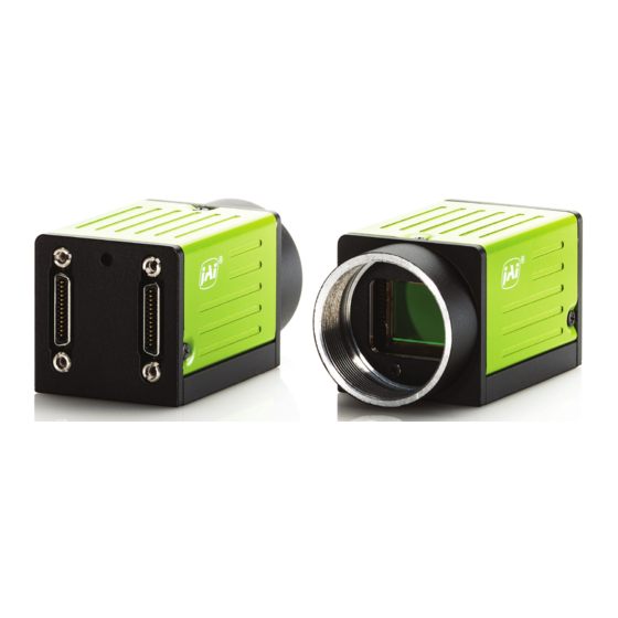
Page 11: Parts Locations And Their Functions
SP-5000M-PMCL / SP-5000C-PMCL 4. Parts locations and their functions 4.1 Parts locations and their functions Lens mount C-mount (Note *1) 10-pin connector AUX interface connector LED Indication for power and trigger input 12-pin connector DC+12V and trigger input ... -
Page 12: Rear Panel
SP-5000M-PMCL / SP-5000C-PMCL Rear Panel The rear panel mounted LED provides the following information: Amber: Power connected – initiating This light goes OFF after initiating. Steady green: Camera is operating in Continuous mode Flashing green: The camera is receiving external triggering ... -
Page 13: Input And Output
SP-5000M-PMCL / SP-5000C-PMCL 5. Input and output Connector and its pin configuration 5.1.1 12-Pin connector 5.1.1.1 Figure Type: HR-10A-10R-12PB(72) Hirose male or equivalent Fig.3 Hirose 12-pin connector 5.1.1.2 Pin configuration Table 1 12-pin configuration Pin no. Signal Remarks DC input +12V ~... -
Page 14: Pin Assignment
SP-5000M-PMCL / SP-5000C-PMCL 5.1.2.2 Pin assignment Table-2 Camera link pin configuration – connector 1 Pin No In/Out Name Note 1,26 Power Power 2(-),15(+) X_OUT0 3(-),16(+) X_OUT1 Data output 4(-),17(+) X_OUT2 5(-),18(+) X_Clk Clock for CL 6(-),19(+) X_OUT3 Data output 7(+),20(-) -
Page 15: Aux Type 2 Hirose 10-Pin Connector (Factory Option)
SP-5000M-PMCL / SP-5000C-PMCL Table -3 AUX Standard Hirose 10-pin connector pin assignment Name Note Motorized Lens DRIVE IRIS+ Motorized Lens DRIVE FOCUS+ Motorized Lens DRIVE ZOOM+ Motorized Lens COMMON P-Iris Lens P-IRIS OUT1A P-Iris Lens P-IRIS OUT1B P-Iris Lens P-IRIS OUT2A... -
Page 16: Camera Link Interface
SP-5000M-PMCL / SP-5000C-PMCL Camera Link interface 5.2.1 Camera Link Interface Table-6 Camera Link interface SP-5000M/C-PMCL Camera Link Configuration Base Medium Full 80bit Full Port Camera Link port/bit 2Tap / 12bit 4Tap / 12bit 8 Tap / 8bit 8 Tap / 10bit... -
Page 17: Camera Link Pixel Clock Frequency
2. Please check whether the frame grabber complies with those formats if you use 80-bit (8-tap/10-bit) camera configuration. 3. If you use 80-bit (8-tap/10-bit) camera configuration, DVAL and Exposure Active (JAI custom) are not output through the Camera Link interface. FVAL is only output via Digital I/O-1 connector. -
Page 18: Digital In/Out Interface
SP-5000M-PMCL / SP-5000C-PMCL Digital IN/OUT interface In the SP-5000M-PMCL and SP-5000C-PMCL, the software control tool can assign the necessary signals used in the system to digital inputs and outputs (see Section 5.3.7.1 for block diagram). 5.3.1 Line Selector In the Line Selector, the following input and output signals can be assigned. -
Page 19: Line Format
SP-5000M-PMCL / SP-5000C-PMCL 5.3.6 Line Format Indicates the interface information of the input and output lines. Not connected, TTL, LVDS or Opto-coupled Note: In the SP-5000-PMCL, Opto-coupled interface is not available. 5.3.7 GPIO GPIO is a general interface for input and output and controls the I/O for trigger signals and other valid signals and pulse generators. -
Page 20: Input And Output Matrix Table
SP-5000M-PMCL / SP-5000C-PMCL 5.3.7.2 Input and output matrix table The relation between input and output is as follows. Table-9 GPIO matrix table Selector (Cross Pulse Generator Trigger Selector Line Selector point switch output) Selector Source signal (Cross point switch input) ... -
Page 21: Clock Pre-Scaler
SP-5000M-PMCL / SP-5000C-PMCL Table - 10 Pulse Generator default settings Display Name Value Clock Pre-scaler Pulse Generator Length Start Repeat Clear Clear Clear Clear Pulse Generator Point Point Count Source Inverter Activation Sync Selector Mode True Async Pulse Generator 0... -
Page 22: Pulse Generator Length
SP-5000M-PMCL / SP-5000C-PMCL Pulse generator Clear source IN (Clear activation = Rising edge Pulse generator repeat count = N Clear SYNC mode (Pulse generator length x N) = Async) Pulse generator Pulse generator Pulse generator length length length Pulse generator... - Page 23 SP-5000M-PMCL / SP-5000C-PMCL (Example 1) Clear Activation = Rising Edge, Clear Sync Mode = Async Mode, Clear Inverter = False Pulse Generator Clear Source In Pulse Generator Output Clear ↓ Fig.8 Counter clear in Async mode (Example 2) Clear Activation = Rising Edge, Clear Sync Mode = Sync Mode,...
-
Page 24: Pulse Generator Clear Source
SP-5000M-PMCL / SP-5000C-PMCL 5.4.9 Pulse Generator Clear Source The following clear sources can be selected as the pulse generator clear signal. Table - 12 Pulse generator clear source Pulse Generator Clear Source Description item Connect Low level signal to Clear Source for the selected pulse generator. -
Page 25: Pulse Generator Inverter
SP-5000M-PMCL / SP-5000C-PMCL 5.4.10 Pulse Generator Inverter Clear Source Signal can be have polarity inverted. 5.4.11 Pulse Generator Setting table Table - 13 Pulse Generator setting parameters Display Name Value Clock Pre-scaler 1 to 4096 Pulse Generator Clock (MHZ) [Pixel Clock:48MHz]÷[Clock Pre-scaler]... -
Page 26: Sensor Layout, Output Format And Timing
SP-5000M-PMCL / SP-5000C-PMCL Sensor layout, output format and timing Sensor layout The CMOS sensors used in the SP-5000M-PMCL and SP-5000C-PMCL have the following pixel layout. 6.1.1 Monochrome sensor Pixel (0,0) 2560 Pixels Fig. 10 Monochrome sensor layout 6.1.2 Bayer sensor... -
Page 27: Camera Output Format (Tap Geometry)
SP-5000M-PMCL / SP-5000C-PMCL Camera output format (Tap Geometry) Table - 14 Output format Camera output format Bit assignment Refer to drawing 1X2–1Y 8-bit, 10-bit, 12-bit 6.2.1 1X4–1Y 8-bit, 10-bit, 12-bit 6.2.2 1X8–1Y 8-bit, 10-bit 6.2.3 1X10⁻¹Y 8-bit 6.2.4 Note: The camera output description is based on GenICam SFNC Ver.1.5.1. - Page 28 SP-5000M-PMCL / SP-5000C-PMCL 6.2.2 1X4–1Y 1X4–1Y is a 4-tap readout system specified in GenICam Tap Geometry and it outputs as the following. Tap 1 Tap 2 Tap 2 Tap 2 Step X = 4 X5120 X2053 X2054 X2055 X2056 X2057...
-
Page 29: Output Timing And Output Image
6.3.1 Horizontal timing The horizontal frequency is changed by setting the Tap Geometry. In the SP-5000M-PMCL and SP-5000C-PMCL, H-binning is available but the horizontal frequency is not changed. Therefore, the frame rate is not increased in H-Binning mode. FVAL Active... - Page 30 SP-5000M-PMCL / SP-5000C-PMCL Table 15. Continuous Trigger / Horizontal timing 1X10⁻¹Y (1/2) Camera Settings LVAL LVAL H-Offset Binning 1: OFF Active Non-Active 2* ON Offset Offset Horizont [Unit: [Unit: [Unit: Width Height Vertical Clock] Clock] Clock] 2560 2048 27 to 30...
- Page 31 SP-5000M-PMCL / SP-5000C-PMCL Table 17. Continuous Trigger / Horizontal timing 1X8-1Y (1/2) Camera Settings LVAL LVAL H-Offset Active Non-Active Binning Offset Offset Horizont [Unit: [Unit: [Unit: Width Height Vertical Clock] Clock] Clock] 4 to 7 2560 2048 (Off) (Off) 164 to 167...
- Page 32 SP-5000M-PMCL / SP-5000C-PMCL Table 18. Continuous Trigger / Horizontal timing 1X8–1Y (2/2) Camera Settings 1Line Binning Horizontal Horizontal Total Frequency Period Clock Offset Offset Horiz Verti Width Height ontal [Unit: Clock] [Unit: kHz] [Unit: us] 324 to 327 253.969 to 3.937 to 3.974...
- Page 33 SP-5000M-PMCL / SP-5000C-PMCL Table 19. Continuous Trigger / Horizontal timing 1X4–1Y (1/2) Camera Settings LVAL LVAL H-Offset Active Non-Active Binning Offset Offset Horizont [Unit: [Unit: [Unit: Width Height Vertical Clock] Clock] Clock] 3 to 6 2560 2048 (Off) (Off) 323 to 326...
- Page 34 SP-5000M-PMCL / SP-5000C-PMCL Table 20. Continuous Trigger / Horizontal timing 1X4–1Y (2/2) Camera Settings 1Line Binning Horizontal Horizontal Total Frequency Period Clock Offset Offset Horiz Verti Width Height ontal [Unit: Clock] [Unit: kHz] [Unit: us] 643 to 646 127.972 to 127.378 7.814 to 7.851...
- Page 35 SP-5000M-PMCL / SP-5000C-PMCL Table 21. Continuous Trigger / Horizontal timing 1X2–1Y (1/2) Camera Settings LVAL LVAL H-Offset Active Non-Active Binning Offset Offset Horizont [Unit: [Unit: [Unit: Width Height Vertical Clock] Clock] Clock] 1280 4 to 7 2560 2048 (Off) (Off)
- Page 36 SP-5000M-PMCL / SP-5000C-PMCL Table 22. Continuous Trigger / Horizontal timing 1X2–1Y (2/2) Camera Settings 1Line Binning Horizontal Horizontal Total Frequency Period Clock Offset Offset Horiz Verti Width Height ontal [Unit: Clock] [Unit: kHz] [Unit: us] 1284 to 1287 64.086 to 63.936 15.604 to 15.641...
-
Page 37: Vertical Timing
DVAL and Exposure Active, which are normally output to Camera Link spare bits, are not output through the Camera Link interface as data bits are applied to those bits. In the SP-5000M-PMCL, H-Binning and V-Binning functions are available but H-Binning function does not make the frame rate faster. -
Page 38: Camera Settings
SP-5000M-PMCL / SP-5000C-PMCL Table 24. Continuous Trigger / Vertical timing 1X10⁻¹Y, 1X8–1Y (1/3) Camera Settings Binning FVAL & FVAL Exposure DVAL V -Offset Time Active -Active (Min) [Unit: Line] [Unit: Line] [Unit: Line] [Unit: us] 2560 2048 2048 110.1 or 111.1... - Page 39 SP-5000M-PMCL / SP-5000C-PMCL Table 25. Continuous Trigger / Vertical timing 1X10⁻¹Y (2/3) Camera Settings Binning Exposure Exposure Frame Time Rate FVAL (Max.) Active Start [Unit: Hz] [Unit: us] [Unit: Line] [Unit: us] 31.5 2560 2048 (Off) (Off) [Frame Period] - 100=...
- Page 40 SP-5000M-PMCL / SP-5000C-PMCL Table 26. Continuous Trigger / Vertical timing 1X8–1Y (3/3) Camera Settings Exposure Binning Exposure Frame Time Rate FVAL (Max.) Active Start [Unit: Hz] [Unit: us] [Unit: Line] [Unit: us] 32.9 2560 2048 (Off) (Off) 36.4 8333 119.96 8333 - 100 = 8233 29.3...
- Page 41 SP-5000M-PMCL / SP-5000C-PMCL Table 27. Continuous Trigger / Vertical timing 1X4–1Y, 1X2–1Y (1/3) Camera Settings Binning FVAL & FVAL Exposure DVAL V -Offset Time Active -Active (Min) [Unit: Line] [Unit: Line] [Unit: Line] [Unit: us] 2560 2048 2048 45.0 or 46.0...
- Page 42 SP-5000M-PMCL / SP-5000C-PMCL Table 28. Continuous Trigger / Vertical timing 1X4–1Y (2/3) Camera Settings Binning Exposure Exposure Active End Frame Time Rate (Max.) FVAL Active Start [Unit: Line] [Unit: us] [Unit: [Unit: us] 11.0 86.5 40.3 2560 2048 (Off) (Off) 16393 - 100 12.0...
-
Page 43: Roi (Region Of Interest) Setting
However, in the horizontal direction, the horizontal frequency is not changed if the width is decreased. In the SP-5000M-PMCL, the minimum width is “16” and minimum height is “1”. In the SP-5000C-PMCL, the minimum width is “16” and minimum height is “2”. -
Page 44: Digital Output Bit Allocation
SP-5000M-PMCL / SP-5000C-PMCL Setting example (1) Setting example (2) Binning Horizontal = 1 Binning Horizontal = 2 Binning Vertical Binning Vertical Readout area Readout area OffsetX Width Width Width OffsetX OffsetY OffsetY Height Height 1280 Width Max 2560 Width Max Fig. -
Page 45: Operating Modes
ROI. ROI setting: Height: 1 line to 2048 lines for SP-5000M-PMCL 2 lines to 2048 lines for SP-5000C-PMCL As for the details of ROI settings, refer to section 6.3.3. - Page 46 SP-5000M-PMCL / SP-5000C-PMCL Table 31. Frame rate calculation (Continuous Trigger, HDR Mode =“Off”) Camera Continuous Trigger / HDR Mode =“Off” Link ART Command Minimum value setting calculation Geometry -Binning Clock [Unit: us] = ROUND((([Height]x284.56)+13495)÷(82.286MHz)x10^6) 82.3 = ROUND((([Height]x284.56)+(13495÷ 2))÷(82.286MHz)x10^6) = ROUND((([Height]x260.86)+13495)÷(75.429MHz)x10^6) 75.4...
- Page 47 SP-5000M-PMCL / SP-5000C-PMCL Table 33. Frame rate setting range(Typical) (Continuous Trigger) (1/2) Camera Settings ART Command value : limited reference Min. Max. Setting value Actual period Setting value Actual time /period 1X10 82.3 2048 7246 137.9 fps (Off) (138.007fps) 1024 3623 275.7 fps...
- Page 48 SP-5000M-PMCL / SP-5000C-PMCL Table 34. Frame rate setting range(Typical) (Continuous Trigger) (2/2) Camera Settings ART Command: Limited Reference Min. Max. Setting Value Actual Period Setting Actual time Value /period 82.3 2048 16327 61.2 fps (Off) (61.248fps) 1024 8163 122.5 fps (On) (122.504fps)
-
Page 49: Exposure Setting
SP-5000M-PMCL / SP-5000C-PMCL 7.2. Exposure setting 7.2.1 Mode Exposure Mode sets which exposure mode is to be used. If the trigger is used, Frame Start must also be used. When Exposure Mode is set to Timed or Trigger Width, the combination of Exposure Mode and Frame Start can set various operations. -
Page 50: Exposureauto
SP-5000M-PMCL / SP-5000C-PMCL Note: In the continuous trigger mode (Frame Start Trigger Mode: OFF), the maximum setting value of the exposure time is limited by the frame rate setting. In the SP-5000-PMCL, the maximum value of exposure time is “Frame Rate – 100”. If the exposure mode is OFF, the maximum value of exposure time is set in the camera. -
Page 51: Triggeractivation
V Binning ON (Full) (Note2) 15.5 ms Note 1: Readout setting in Trigger Overlap is not available Note 2: SP-5000M-PMCL only 7.5. Timed mode (EPS operation) This mode captures image(s) with a preset exposure time by using the external trigger. An additional setting determines if the trigger pulse can be accepted during the exposure period. -
Page 52: If Overlap Setting Is Readout
SP-5000M-PMCL / SP-5000C-PMCL Table - 39 Trigger minimum interval (Trigger Overlap = Readout) (1X8–1Y) Time (Min. Trigger Trigger Mode Readout Mode Period) Full 30.9 ms + 8.01 µs AOI Center 2/3 21.5 ms + 8.01 µs Timed Exposure Mode AOI Center 1/2 15.5 ms + 8.01 µs... -
Page 53: If Overlap Setting Is Off
SP-5000M-PMCL / SP-5000C-PMCL Trigger width mode (PWC) In this mode, the exposure time is equal to the trigger pulse width. Accordingly, longer exposure times are supported. Additional settings determine if the trigger pulse can be accepted during the exposure period. -
Page 54: If Overlap Setting Is Readout
SP-5000M-PMCL / SP-5000C-PMCL 7.6.2 If Overlap setting is Readout Trigger CMOS Exposure Exposure Active Exposure Period FVAL 2L (Min.) 208 clocks 7L to 8L Fig. 24 Overlap: Readout - 52 -... -
Page 55: Rct Mode
SP-5000M-PMCL / SP-5000C-PMCL 7.7. RCT mode Until the trigger is input, the camera operates continuously and the video signal for the auto-iris lens is output. At this moment, the video signal, FVAL and LVAL are output but DVAL is not output. When the trigger is input, the fast dump is activated to read out the electronic charge very quickly, after which the accumulation and the readout are performed. -
Page 56: Piv (Particle Image Velocimetry)
3.9 ms x 2 + Exposure time + 8.01 µs V Binning ON (Full) 15.5 ms x 2 + Exposure time + 8.01 µs (Note2) Note 1. Overlap mode=Readout is not available Note 2. SP-5000M-PMCL only Trigegr Exposure Exposure Active... -
Page 57: Video Send Mode
15.5ms + Exposure time + 8.01µs (Note 1) Note 1: SP-5000M-PMCL only Note 2: The minimum trigger interval assumes that the exposure time is the same for each index in the sequence. If the exposure time is different, the difference in period should be added to the interval calculation. -
Page 58: Sequence Roi Setting Parameters
SP-5000M-PMCL / SP-5000C-PMCL Table 44. Sequence mode: Sequence Index default value Sequence ROI Offset Gain Selector Binning Exposure Black Frame Next Width Height Gain Time Level Enable Count Index Sequence Blue Horizontal Vertical (ALL) ROI Index Index - Index 0... - Page 59 In Sequence ROI Gain Selector, the gain settings for each index are available. SP-5000C-PMCL: Gain(ALL), Red and Blue can be set. SP-5000M-PMCL: Only Gain is displayed and can be set. (7) Sequence ROI Black Level Black Level setting is available for each index.
-
Page 60: Multi Roi Function
SP-5000M-PMCL / SP-5000C-PMCL “Normal” “Normal” “Trigger Sequence” “Trigger Sequence” Video Send Mode Sequence Index Sequence Index Sequence Index Sequence Index Can be changed Can be changed Cannot be changed Cannot be changed Sequence Reset “Execute” Command Sequence Index Pointer Sequen &... - Page 61 SP-5000M-PMCL / SP-5000C-PMCL (2) Multi ROI Width The setting range and Step number are the same as the normal ROI setting in which [Width] plus [Offset X] should be equal to [Width Max]. In Multi ROI operation, the maximum offset value in index 1 to index 8 is the object in this calculation.
- Page 62 SP-5000M-PMCL / SP-5000C-PMCL ROI setting explanation if Multi ROI Index Max is set to 4 Index 4 Offset Y Index 2 Offset Y Index 1 Offset X Index 3 Offset X Index 1 Offset X Index 1 Height Index 2...
-
Page 63: Operation And Function Matrix
SP-5000M-PMCL / SP-5000C-PMCL Fig. 29 Multi ROI settings and output image 7.11. Operation and function matrix Table - 46 Operation and function matrix Auto Binning Binning Exposure Trigger Trigger Exposure White Auto Iris Auto Auto Vertical Horizontal Overlap operation Mode... -
Page 64: Other Functions
SP-5000M-PMCL / SP-5000C-PMCL Other functions Black level control This function adjusts the setup level. Variable range: -256 to 255 LSB (at 10-bit output) 8.1.1 Black Level Selector The following items can be adjusted. Monochrome: Black Level All Color: Black Level All/ Black Level Red/ Black Level Blue 8.1.2... -
Page 65: Gain Selector
Gain Raw Digital All:100 ~ 1600(0dB~24dB) Gain Raw Digital Red / Gain Raw Digital Blue :-4533~37876 8.2.4 Gain Auto This provides automatic control of the gain level. This is controlled by the command JAI ALC Reference. There are three modes. OFF: Adjust manually. Once:... -
Page 66: Lut
SP-5000M-PMCL / SP-5000C-PMCL Gain Auto Min: The minimum value of GainAuto control range can be set ALC Reference: The reference level of Gain Auto control can be set (common with Exposure Auto) ALC channel area: The measurement area of GainAuto control can be set, either... -
Page 67: Gamma
SP-5000M-PMCL / SP-5000C-PMCL Fig.32 LUT data processing method Gamma This command is used set gamma between gamma 0.45 and gamma 1.0 (OFF). 8 steps are provided. The gamma value is an approximate value. Fig.33 Gamma correction Shading Correction This function compensates for shading (non-uniformity) caused by the lens or the light source used. -
Page 68: Blemish Compensation
SP-5000M-PMCL / SP-5000C-PMCL Before adjustment After adjustment Fig. 35 Concept drawing of color shading correction Note: Under the following conditions, the shading correction circuit may not work properly. If there is some area in the image with a video level less than 70% ... -
Page 69: Alc
ALC Reference is set to 100% video level, AGC, Auto Shutter and/or Auto iris will function to maintain 100% video level. HDR (High Dynamic Range) (SP-5000M-PMCL only) HDR sensing mode can be set when HDR Mode is set to ON while Exposure Mode is Timed. -
Page 70: Lens
Dynamic Range [%] (200) (400) (800) (1600) 8.9. Lens The SP-5000M-PMCL and SP-5000C-PMCL can be used with 4 different types of lenses. The lens used must be selected in Lens Select. Table -47 Lens selector Lens Select Description (Control with Note... -
Page 71: About P-Iris
8.9.3 Motorized lens The SP-5000M-PMCL and SP-5000C-PMCL can use a motorized lens for zoom, focus and iris. The following functions are available to control the lens via the 10-pin AUX connector. 8.9.3.1 Iris Open: While this command is being sent, the iris continues to open. -
Page 72: Zoom
SP-5000M-PMCL / SP-5000C-PMCL 8.9.3.2 Zoom Wide: While this command is being sent, the zoom continues to move towards wide angle. Tele: While this command is being sent, the zoom continues to move towards telephoto. Stop: When this command is supplied, the zoom operation stops. -
Page 73: Camera Control
2. The frame grabber used must be compliant with Camera Link Specification v1.1 or greater in order to communicate with the JAI SDK and Control Tool. If it is not, the JAI SDK and Control Tool cannot be used, and the Short ASCII communication protocol and associated control tool should be used instead. -
Page 74: External Appearance And Dimensions
SP-5000M-PMCL / SP-5000C-PMCL External appearance and dimensions ( 9. 8) 24. 5 3- M3 Dept h5 5. 2 0. 3 3- M3 Dept h5 ( 9. 8) 24. 5 POWER /TRIG AU X D C IN / TRIG DI GITAL I/O -2... -
Page 75: Specifications
SP-5000M-PMCL / SP-5000C-PMCL Specifications 11.1. Camera spectral response 80.00 70.00 60.00 50.00 40.00 30.00 20.00 10.00 0.00 1000 wavelength (nm) Fig.41 SP-5000M-PMCL Spectral response Fig.42 SP-5000C-PMCL Spectral response - 73 -... -
Page 76: Specification Table
SP-5000M-PMCL / SP-5000C-PMCL 11.2. Specification table Table – 48 Specification table Specifications SP-5000M-PMCL SP-5000C-PMCL Scanning system Progressive scan Synchronization Internal CameraLink Specifications (V.2.0 RC2), Conforming with PoCL specifications Interface Camera Link Pixel Clock: 61.7 MHz, 75.4 MHz, 82.3 MHZ selectable (Default setting: 82.3 MHz) - Page 77 SP-5000M-PMCL / SP-5000C-PMCL 1280 pixels — The frame rate is not changed. 2048 lines 2048 lines V Binning — 1024 lines 8-bit, 10-bit, 12-bit Bit assignment 8-bit, 10-bit, 12-bit Acquisition Mode Continuous Trigger selector Frame Start Trigger mode Continuous, Timed(EPS), Trigger Width,...
- Page 78 SP-5000M-PMCL / SP-5000C-PMCL Operating temperature -45C to +70C / 20% – 80% (non-condensing) / Humidity Storage Temp. / Humidity -45C to +70C / 20% - 80 % (non-condensing) Regulation CE (EN61000-6-2 and EN61000-6-3), FCC part 15 class B, RoHS, WEEE Housing Dimensions 62 x 62 x 55.5 mm (W x H x D) (excluding protrusion)
-
Page 79: Appendix 1 Short Ascii Command Communication Protocol
SP-5000M-PMCL / SP-5000C-PMCL Appendix 1 Short ASCII Command Communication Protocol This chapter described the communication control protocol based on the short ASCII command as the reference 1 Communication setting Baud Rate 9600 Data Length 8bit Start Bit 1bit Stop Bit... -
Page 80: Command List (Short Ascii Command)
SP-5000M-PMCL / SP-5000C-PMCL 3. Rewrite new baud rate again with new baud rate (Confirmation command) Send to camera: CBDRT=16(0x10) <CR><LF> Camera response: COMPLETE<CR><LF> In case the camera does not receive the confirming command with new baud rate within 250 ms after sending the acknowledgement it falls back to the original baud rate (9600 bps). -
Page 81: Device Control
SP-5000M-PMCL / SP-5000C-PMCL 2.4.3 Device Control Acce Short DEFA Name Interface Values Description ASCII DeviceFirmwar I String Firm Ver. No. VN?<CR><LF> - - - Version DeviceReset Comman CRS00 CRS00=1<CR><LF> - - - 2.4.4 Image Format Control Acce Short DEFA Name... -
Page 82: Acquisition Control
SP-5000M-PMCL / SP-5000C-PMCL 2.4.5 Acquisition Control Acce Short DEFA Name Interface Values Description ASCII FrameStartTrig TM=[Param.]<CR><LF> Enumera Off/On Mode TM?<CR><LF> tion (R)/ TrigSoftware Comman STRG STRG=0<CR><LF> - - - 0: Low 1: High 2: SoftTrigger 8: PulseGenerator0 9: PulseGenerator1 10: PulseGenerator2 FrameStartTrig TI=[Param.]<CR><LF>... -
Page 83: Digital I/O Control
SP-5000M-PMCL / SP-5000C-PMCL 2.4.6 Digital I/O Control Acces Short Name Interface Values Description ASCII LI0=[Param.]<CR><LF> LineInverter_Line1 I Boolean False/True LI0?<CR><LF> LI1=[Param.]<CR><LF> LineInverter_Line8 I Boolean False/True LI1?<CR><LF> LI2=[Param.]<CR><LF> LineInverter_Line9 I Boolean False/True LI2?<CR><LF> LineInverter_Nand0In ND0IN ND0INV1=[Param.]<CR><LF> I Boolean False/True ND0INV1?<CR><LF> LineInverter_Nand0In ND0IN ND0INV2=[Param.]<CR><LF>... -
Page 84: Analogue Control
SP-5000M-PMCL / SP-5000C-PMCL Same as for ND1IN2=[Param.]<CR><LF> LineSource_Nand1In2 Enume ND1IN2 Line1 ND1IN2?<CR><LF> ration 2.4.7 Analogue Control Short DEFAU Name Interface Values Description ASCII FGA=[Param.]<CR><L GainRawDigital I Integer 1600 F> min~0~max FGA?<CR><LF> PGR=[Param.]<CR><L GainRawDigital F> I Integer -4533 28400 min~0~max RedAll PGR?<CR><LF>... -
Page 85: Transport Layer Control
SP-5000M-PMCL / SP-5000C-PMCL 2.4.9 Transport Layer Control Acce Short DEFAU Name Interface Values Description ASCII 1: Geometry_1X2_1Y TAGM=[Param.]<CR>< DeviceTapGeom 3: Geometry_1X4_1Y Enumera TAGM LF> etry 5: Geometry_1X8_1Y tion TAGM?<CR><LF> 6: Geometry_1X10_1Y 2.4.10 User Set Control Short Name Interface Access Values... - Page 86 SP-5000M-PMCL / SP-5000C-PMCL 4=Busy. 5=Limit. 6= Trig is not set as Normal. 0: OFF SDM=[Param.]<CR><LF 1: User 1 ShadingMode Enumera > 2: User 2 tion SDM?<CR><LF> 3: User 3 0: Normal 1: Trigger Sequence VSM=[Param.]<CR><LF VideoSendMode Enumera Command > tion Sequence VSM?<CR><LF>...
- Page 87 SP-5000M-PMCL / SP-5000C-PMCL SequenceModeN SQNI3=[Param.]<CR>< Same Enumera SQNI3 LF> SequenceRoiIndex Index2 tion SQNI3?<CR><LF> SequenceModeN SQNI4=[Param.]<CR>< Same Enumera SQNI4 LF> SequenceRoiIndex Index3 tion SQNI4?<CR><LF> SequenceModeN SQNI5=[Param.]<CR>< Same Enumera SQNI5 LF> SequenceRoiIndex Index4 tion SQNI5?<CR><LF> SequenceModeN SQNI6=[Param.]<CR>< Same Enumera SQNI6 LF> SequenceRoiIndex...
- Page 88 SP-5000M-PMCL / SP-5000C-PMCL 1(Mon SQH10=[Param.]<CR>< SequenceMode I Integer SQH10 2048 2048 LF> Min~Max Height9 2(Bay SQH10?<CR><LF> 2047 (Mno) SQOY1=[Param.]<CR>< SequenceMode I Integer SQOY1 2046 LF> Min~Max OffsetY0 (Baye SQOY1?<CR><LF> 2047 (Mno) SQOY2=[Param.]<CR>< SequenceMode I Integer SQOY2 Min~Max 2046 LF> OffsetY1 (Baye SQOY2?<CR><LF>...
- Page 89 SP-5000M-PMCL / SP-5000C-PMCL SQGA3=[Param.]<CR> SequenceMode I Integer SQGA3 1600 <LF> Min~Max Gain2 SQGA3?<CR><LF> SQGA4=[Param.]<CR> SequenceMode I Integer SQGA4 1600 <LF> Min~Max Gain3 SQGA4?<CR><LF> SQGA5=[Param.]<CR> SequenceMode I Integer SQGA5 1600 <LF> Min~Max Gain4 SQGA5?<CR><LF> SQGA6=[Param.]<CR> SequenceMode I Integer SQGA6 Min~Max 1600 <LF>...
- Page 90 SP-5000M-PMCL / SP-5000C-PMCL SQHB2=[Param.]<CR>< SequenceMode 1: Hbinning = OFF LF> Enumera SQHB2 Hbinning1 2: Hbinning = ON SQHB2?<CR><LF> tion (Mono model only) SQHB3=[Param.]<CR>< SequenceMode 1: Hbinning = OFF LF> Enumera SQHB3 Hbinning2 2: Hbinning = ON SQHB3?<CR><LF> tion (Mono model only) SQHB4=[Param.]<CR><...
- Page 91 SP-5000M-PMCL / SP-5000C-PMCL SQVB7=[Param.]<CR>< SequenceMode 1: Hbinning = OFF LF> Enumera SQVB7 Vbinning6 2: Hbinning = ON SQVB7?<CR><LF> tion (Mono model only) SQVB8=[Param.]<CR>< SequenceMode 1: Hbinning = OFF LF> Enumera SQVB8 Vbinning7 2: Hbinning = ON SQVB8?<CR><LF> tion (Mono model only) SQVB9=[Param.]<CR><...
- Page 92 SP-5000M-PMCL / SP-5000C-PMCL SQBL6=[Param.]<CR>< SequenceMode I Integer SQBL6 -256 LF> Min~Max BlackLevel5 SQBL6?<CR><LF> SQBL7=[Param.]<CR>< SequenceMode I Integer SQBL7 -256 LF> Min~Max BlackLevel6 SQBL7?<CR><LF> SQBL8=[Param.]<CR>< SequenceMode I Integer SQBL8 -256 LF> Min~Max BlackLevel7 SQBL8?<CR><LF> SQBL9=[Param.]<CR>< SequenceMode I Integer SQBL9 -256 LF>...
- Page 93 SP-5000M-PMCL / SP-5000C-PMCL SQPGB2=[Param.]<CR SequenceMode SQPGB ><LF> I Integer -4533 17713 Min~Max GainBlue1 SQPGB2?<CR><LF> (Bayer model only) SQPGB3=[Param.]<CR SequenceMode SQPGB ><LF> I Integer -4533 17713 Min~Max GainBlue2 SQPGB3?<CR><LF> (Bayer model only) SQPGB4=[Param.]<CR SequenceMode SQPGB ><LF> I Integer Min~Max -4533 17713 GainBlue3 SQPGB4?<CR><LF>...
- Page 94 SP-5000M-PMCL / SP-5000C-PMCL MRH3=[Param.]<CR>< MultiRoiHeight3 I Integer MRH3 3840 LF> Min~Max MRH3?<CR><LF> MRH4=[Param.]<CR>< MultiRoiHeight4 I Integer MRH4 3840 LF> Min~Max MRH4?<CR><LF> MRH5=[Param.]<CR>< MultiRoiHeight5 I Integer MRH5 3840 LF> Min~Max MRH5?<CR><LF> MRH6=[Param.]<CR>< MultiRoiHeight6 I Integer MRH6 3840 LF> Min~Max MRH6?<CR><LF> MRH7=[Param.]<CR><...
- Page 95 SP-5000M-PMCL / SP-5000C-PMCL MROY6=[Param.]<CR> MultiRoiOffsetY I Integer MROY6 3839 <LF> Min~Max MROY6?<CR><LF> MROY7=[Param.]<CR> MultiRoiOffsetY I Integer MROY7 3839 <LF> Min~Max MROY7?<CR><LF> MROY8=[Param.]<CR> MultiRoiOffsetY I Integer MROY8 3839 <LF> Min~Max MROY8?<CR><LF> 0: Off LUTC=[Param.]<CR><L LUTMode Enumera LUTC 1: Gamma F> tion 2: LUT LUTC?<CR><LF>...
- Page 96 SP-5000M-PMCL / SP-5000C-PMCL 0: None 1: P-IRIS Lens AIS=[Param.]<CR><LF> LensSelect Enumera 2: MOTOR Iris Lens AIS?<CR><LF> tion 3: Video Iris Lens 4: DC Iris Lens 0: Video VideoIrisStateC ISC=[Param.]<CR><LF> Enumera 1: Close ontrol ISC?<CR><LF> tion 2: Open ALCA=[Param.]<CR><L ALCChannelAre Enumera...
- Page 97 SP-5000M-PMCL / SP-5000C-PMCL AWBA=[Param.]<CR>< AWBChannelAre Enumera AWBA 0: Off / 1: On LF> aAll tion AWBA?<CR><LF> AWBChannelAre Enumera AWBLR 0: Off / 1: On LowRight tion AWBChannelAre AWBLM Enumera 0: Off / 1: On LowMidRight tion AWBChannelAre AWBLM Enumera 0: Off / 1: On...
- Page 98 SP-5000M-PMCL / SP-5000C-PMCL 0: Factory area EA?<CR><LF> CurrentAreaNoR 1: User 1 area The camera return the I Integer equest 2: User 2 area latest used DATA 3: User 3 area AREA. PLS=[Param.]<CR><LF PirisLensSelect Enumera No lens available > tion PLS?<CR><LF>...
- Page 99 SP-5000M-PMCL / SP-5000C-PMCL PGL1=[Param.]<CR><L GpioPulseGenLe 10485 I Integer PGL1 F> Min~Max ngth1 PGL1?<CR><LF> PGL2=[Param.]<CR><L GpioPulseGenLe 10485 I Integer PGL2 F> Min~Max ngth2 PGL2?<CR><LF> PGL3=[Param.]<CR><L GpioPulseGenLe 10485 I Integer PGL3 F> Min~Max ngth3 PGL3?<CR><LF> PGST0=[Param.]<CR>< GpioPulseGenSt 10485 I Integer PGST0 Min~Max LF>...
- Page 100 SP-5000M-PMCL / SP-5000C-PMCL PGSM0=[Param.]<CR> GpioPulseGenSy 0: Async Mode Enumera PGSM0 <LF> nc Mode0 1: Sync Mode tion PGSM0?<CR><LF> PGSM1=[Param.]<CR> GpioPulseGenSy Enumera PGSM1 Same as above. <LF> nc Mode1 tion PGSM1?<CR><LF> PGSM2=[Param.]<CR> GpioPulseGenSy Enumera PGSM2 Same as above. <LF> nc Mode2 tion PGSM2?<CR><LF>...
- Page 101 SP-5000M-PMCL / SP-5000C-PMCL 0: Low 1: High 2: FrameTriggerWait 3: FramActive 4: ExposureActive ND0N1=[Param.]<CR> GpioNand0Input 5: Fval Enumera ND0IN1 <LF> Source1 6: PulseGenerator0 tion ND0IN1?<CR><LF> 7: PulseGenerator1 8: PulseGenerator2 9: PulseGenerator3 10: TTL_In1 11: CL_CC1_In ND1N1=[Param.]<CR> GpioNand1Input Enumera ND1IN1 Same as above.
- Page 102 SP-5000M-PMCL / SP-5000C-PMCL BlemishNum I Integer BNUM BNUM?<CR><LF> Min~Max 0= 82.3MHz CLCF=[Param.]<CR><L CameraLinkCloc Enumera CLCF 1= 75.4MHz F> kFrequency tion 2= 61.7MHz CLCF?<CR><LF> VPB=[Param.]<CR><LF VideoProcessBy Enumera 0: Off / 1: On > pass tion VPB?<CR><LF> HighDynamicRa HES=[Param.]<CR><LF Enumera 0: Off / 1: On >...
-
Page 103: Appendix 2
SP-5000M-PMCL / SP-5000C-PMCL Appendix 2 1. Precautions Personnel not trained in dealing with similar electronic devices should not service this camera. The camera contains components sensitive to electrostatic discharge. The handling of these devices should follow the requirements of electrostatic sensitive components. -
Page 104: Exportation
5. Exportation When exporting this product, please follow the export regulation of your own country. 6. References 1. This manual and a datasheet for SP-5000M-PMCL / SP-5000C-PMCL can be downloaded from www.jai.com 2. Camera control software can be downloaded from www.jai.com... -
Page 105: Manual Change History
SP-5000M-PMCL / SP-5000C-PMCL Manual change history Date Revision Changes Sept. 2013 Ver.1.0 New release Oct. 2013 Ver.1.1 Add EMVA1288 spec. for SP-5000C-PMCL - 103 -... -
Page 106: User's Record
Company and product names mentioned in this manual are trademarks or registered trademarks of their respective owners. JAI A-S cannot be held responsible for any technical or typographical errors and reserves the right to make changes to products and documentation without prior notification.
Need help?
Do you have a question about the SP-5000M-PMCL and is the answer not in the manual?
Questions and answers