
Related Manuals for Club Car PowerDrive

Summary of Contents for Club Car PowerDrive
- Page 1 POWERDRIVE BATTERY CHARGER OWNER’S MANUAL Manual Number 101993811 Edition Code 0898U0313T...
- Page 2 Page 2 PowerDrive Battery Charger Owner’s Manual...
- Page 3 NOTICE Club Car is not liable for errors in this manual or for incidental or consequential damages that result from the use of the material in this manual. The Club Car Limited Warranty appears at the end of this manual. No other warranties, express or implied, are contained herein.
- Page 4 Page 4 PowerDrive Battery Charger Owner’s Manual...
-
Page 5: Table Of Contents
PowerDrive Onboard Charger Features ........ -
Page 6: Safety Details
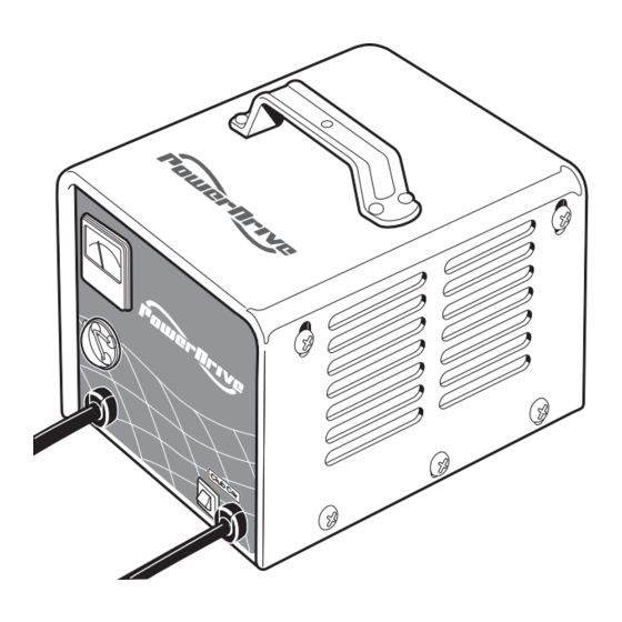
(located on the rear panel) for AC input voltage selection (Figure 8). The PowerDrive battery charger is automatic and has no external controls. When the charger is connected, there is a 2 to 15 second delay before charging begins. - Page 7 The computer accomplishes this by detecting when the exact amount of energy necessary has been returned to the batter- ies. Figure 1 Domestic PowerDrive External Charger Figure 2 Export PowerDrive External Charger Models 17930-11, 17930-18, and 17930-19...
- Page 8 General Information Figure 5 Export PowerDrive Onboard Charger Figure 6 Domestic PowerDrive Onboard Charger Models 17790-10, 17790-20, 17790-30, and 17790-40 Model 19770-98 220 V AC INPUT VOLTAGE SELECTION SWITCH (REAR CHARGER PANEL) Figure 7 Export PowerDrive Onboard Charger Figure 8 AC Input Voltage Selection Switch...
-
Page 9: Powerdrive External Charger Features
POWERDRIVE EXTERNAL CHARGER FEATURES • Charge Interlock PowerDrive battery charger DC plugs have three pins rather than two blades common on most stan- dard charger plugs. Two of these pins are the positive and negative leads as on standard chargers; the third pin is a sensing lead that is the communication link between the charger and the onboard com- puter. -
Page 10: Battery Warning Light
UL AND CSA LISTING When operated on a 120-volt / 60 Hz electrical system, the following PowerDrive battery chargers have been listed by Underwriters Laboratories and by the Canadian Underwriters (thereby meeting the criteria of the Canadian Standards Association). -
Page 11: External Charger Installation And Operation
ý WARNING • Only trained technicians should repair or service the charger. Contact your nearest Club Car distributor/dealer. • Each charger should have its own dedicated 15 or 20 ampere separately protected (circuit breaker or fuse) single phase branch circuit, in accordance with all applicable electrical codes for the location. -
Page 12: External Charger Ac Power Connection
NOTE: Make sure that the AC cord provided with your charger has the proper AC plug (as approved by the local code) for your location. If it does not, contact your Club Car representative to obtain the proper cord or plug. - Page 13 (Figure 12). 3. PowerDrive and PowerDrive Plus vehicles: 10 to 20 seconds after the charger activates, it will shut off again to run a self-diagnostic program (the ammeter will drop to 0). Charging will resume in a few moments (ammeter will return to previous rate of charge).
-
Page 14: External Charger Plug And Receptacle
(ammeter will drop to zero). Charging will resume in a few moments (ammeter returns to previous rate of charge). NOTE: PowerDrive and PowerDrive Plus vehicles: If the batteries are in a fully charged state and the vehicle has not been driven, the onboard computer will not perform the self-diagnostic test. -
Page 15: Checking Battery Condition With An External Charger
It is common practice for technicians to check the condition of a set of batteries after they have been charged to ensure they have received a complete charge before the vehicle is used. With IQ System, PowerDrive, and PowerDrive Plus vehicles, this is not necessary; the onboard computer controls and monitors the charge cycle. -
Page 16: Onboard Charger Operation
ý WARNING • Only trained technicians should repair or service the charger. Contact your nearest Club Car distributor/dealer. • Each charger should have its own dedicated 15 or 20 ampere separately protected (circuit breaker or fuse) single phase branch circuit, in accordance with all applicable electrical codes for the location. -
Page 17: Onboard Charger Ac Power Connection
NOTE: Make sure that the AC cord provided with your charger has the proper AC plug (as approved by the local code) for your location. If it does not, contact your Club Car representative to obtain the proper cord or plug. -
Page 18: Checking Battery Condition With An Onboard Charger
It is common practice for technicians to check the condition of a set of batteries after they have been charged to ensure they have received a complete charge before the vehicle is used. With IQ System, PowerDrive, and PowerDrive Plus vehicles, this is not necessary; the onboard computer controls and monitors the charge cycle. -
Page 19: Battery Charger Specifications
33.0 lb Weight (14.1 kg) (14.3 kg) (15.0 kg) MOUNTING CONFIGURATION Mounting: Set on shelf, wall mount with keyhole, or hang securely from ceiling. • • • Mounting: Onboard (secured to the vehicle) PowerDrive Battery Charger Owner’s Manual Page 19... - Page 20 (17.1 kg) (17.3 kg) (17.3 kg) (17.1 kg) MOUNTING CONFIGURATION Mounting: Set on shelf, wall mount with keyhole, or hang securely from ceiling. Mounting: Onboard (secured to the vehicle) • • • • • Page 20 PowerDrive Battery Charger Owner’s Manual...
- Page 21 Normal Operating Temperature (-30C to 50C) (-30C to 50C) (-30C to 50C) (-30C to 50C) MOUNTING CONFIGURATION Mounting: Set on shelf, wall mount with keyhole, or hang securely • • • • from ceiling. PowerDrive Battery Charger Owner’s Manual Page 21...
- Page 22 (-30C to (-30C to (-30C to 50C) 50C) 50C) 50C) 50C) 50C) MOUNTING CONFIGURATION Mounting: Set on shelf, wall mount with keyhole, • • • • • • or hang securely from ceiling. Page 22 PowerDrive Battery Charger Owner’s Manual...
-
Page 23: Specifications
EXPORT POWERDRIVE ONBOARD CHARGER Export PowerDrive Onboard Battery Charger SPECIFICATIONS Model number 19710 17790-10 17790-20 17790-30 17790-40 (CCP/N) (101964302) (101814302) (101814305) (101814306) (102546902) AC INPUT AC voltage: 100, 200, 220, or 240 VAC • • • • • (selectable) AC voltage (acceptable range):... -
Page 24: Club Car ® Limited Four Year Warranty For Powerdrive ® Chargers
CLUB CAR, LLC, (“CLUB CAR”) hereby warrants to the original retail purchaser that its new PowerDrive Chargers purchased from CLUB CAR or an authorized distributor or dealer will be free from defects in material and workmanship under normal use and service for a period of four years from the date of purchase, subject to the terms, provisions, limitations, and exclusions contained herein.
Need help?
Do you have a question about the PowerDrive and is the answer not in the manual?
Questions and answers
Charger will not come on
The Club Car PowerDrive charger won't turn on because the battery voltages are too low. The charger requires a minimum voltage level to activate. If the individual battery voltages are 8V or less, they need to be charged up to at least 8.6V using a 12V charger for a short period to allow the onboard computer (OBC) to recognize the charge and enable the cart charger.
This answer is automatically generated
@Mr. Anderson
Tried that charger still didn’t work is there a reset button
Yes, the PowerDrive 2 charger has a reset or breaker button on the front, as mentioned in the context where a user reports that their charger trips the reset button.
This answer is automatically generated