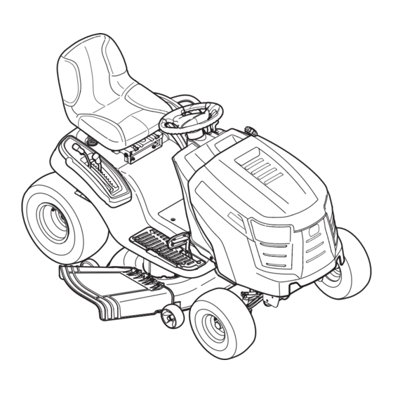
Cub Cadet LTX 1042 Operator's Manual
Hydrostatic lawn tractor
Hide thumbs
Also See for LTX 1042:
- Operator's manual (144 pages) ,
- Compatibility manual (3 pages) ,
- Operator's manual (68 pages)
Table of Contents
Advertisement
Safe Operation Practices • Set-Up • Operation • Maintenance • Service • Troubleshooting • Warranty
O
'
M
peratOr
s
anual
Hydrostatic Lawn Tractor — LTX 1042
WARNING
READ AND FOLLOW ALL SAFETY RULES AND INSTRUCTIONS IN THIS MANUAL
BEFORE ATTEMPTING TO OPERATE THIS MACHINE.
FAILURE TO COMPLY WITH THESE INSTRUCTIONS MAY RESULT IN PERSONAL INJURY.
CUB CADET LLC, P.O. BOX 361131 CLEVELAND, OHIO 44136-0019
Printed In USA
Form No. 769-04348
(August 27, 2008)
Advertisement
Table of Contents

Related Manuals for Cub Cadet LTX 1042


Summary of Contents for Cub Cadet LTX 1042
- Page 1 READ AND FOLLOW ALL SAFETY RULES AND INSTRUCTIONS IN THIS MANUAL BEFORE ATTEMPTING TO OPERATE THIS MACHINE. FAILURE TO COMPLY WITH THESE INSTRUCTIONS MAY RESULT IN PERSONAL INJURY. CUB CADET LLC, P.O. BOX 361131 CLEVELAND, OHIO 44136-0019 Printed In USA Form No. 769-04348...
-
Page 2: Table Of Contents
Visit us on the web at www.cubcadet.com ◊ Call a Customer Support Representative at (800) 965-4CUB ◊ Locate your nearest Cub Cadet Dealer at (877) 282-8684 ◊ Write us at Cub Cadet LLC • P.O. Box 361131 • Cleveland, OH • 44136-0019... -
Page 3: Safe Operation Practices
Important Safe Operation Practices WARNING! This symbol points out important safety instructions which, if not followed, could endanger the personal safety and/or property of yourself and others. Read and follow all instructions in this manual before attempting to operate this machine. Failure to comply with these instructions may result in personal injury. - Page 4 A missing or damaged discharge cover can cause blade Slope Operation contact or thrown object injuries. Slopes are a major factor related to loss of control and tip-over Stop the blade(s) when crossing gravel drives, walks, or accidents which can result in severe injury or death. All slopes roads and while not cutting grass.
- Page 5 Service Children Tragic accidents can occur if the operator is not alert to the Safe Handling of Gasoline: presence of children. Children are often attracted to the machine and the mowing activity. They do not understand To avoid personal injury or property damage use extreme the dangers.
-
Page 6: Spark Arrestor
Do not modify engine Periodically check to make sure the blades come to complete stop within approximately (5) five seconds after To avoid serious injury or death, do not modify engine in any operating the blade disengagement control. If the blades way. -
Page 7: Safety Symbols
Safety Symbols This page depicts and describes safety symbols that may appear on this product. Read, understand, and follow all instructions on the machine before attempting to assemble and operate. Symbol Description READ THE OPERATOR’S MANUAL(S) Read, understand, and follow all instructions in the manual(s) before attempting to assemble and operate DANGER—... - Page 8 2 — i ectiOn MpOrtant peratiOn ractices...
-
Page 9: Assembly & Set-Up
Assembly & Set-Up Contents of Crate • One Lawn Tractor • One Oil Drain Tube • One Deck Wash Hose Coupler • One Lawn Tractor Operator’s Manual • One Kohler Engine Operator’s Manual Tractor Set-Up Shipping Brace Removal WARNING! Make sure the lawn tractor’s engine is Moving The Tractor Manually off, set the parking brake and remove the ignition Your tractor’s transmission is equipped with a hydrostatic... - Page 10 Attaching the Negative Battery Cable Setting the Deck Gauge Wheels NOTE: The positive battery terminal is marked Pos. (+). The Move the tractor on a firm and level surface, preferably negative battery terminal is marked Neg. (–). pavement, and proceed as follows The positive cable (heavy red wire) is secured to the positive Select the height position of the cutting deck by placing battery terminal (+) with a hex bolt and hex nut at the factory.
- Page 11 Adjusting the Seat To adjust the position of the seat, pull up and hold the seat adjustment lever. Slide the seat forward or rearward to the desired position; then release the adjustment lever. Make sure seat is locked into position before operating the tractor. See Fig. 3-5.
-
Page 12: Controls & Features
Controls and Features Systems Indicator Monitor Fuel Tank Cap Ignition Switch Module Throttle/Choke Control Fuel Level Indicator Drive Pedal Brake Pedal Reverse Pedal Parking Brake/ Cargo Net Cruise Control Lever Deck Lift Lever Seat Adjustment Lever PTO (Blade Engage) Handle Storage Bin Cup Holder Figure 4-1... - Page 13 Ground speed is also controlled with the your Cub Cadet dealer. reverse pedal. The further downward the Cargo Net pedal is pivoted, the faster the tractor will travel.
- Page 14 Fuel Level Indicator The Fuel Level Indicator is located on the left side of the tractor’s dash and indicates the amount of fuel in the gas tank. PTO / Blade Engage Handle Activating the PTO engages power to the cutting deck or other (separately available) attachments.
-
Page 15: Operation
If the interlock system should ever WARNING! If you strike a foreign object, stop the malfunction, do not operate the tractor. Contact your Cub Cadet engine and disconnect the spark plug wire(s). dealer. Thoroughly inspect the machine for any damage. -
Page 16: Driving The Tractor
Driving The Tractor Reverse Caution Mode WARNING! The REVERSE CAUTION MODE position of the key switch module Avoid sudden starts, excessive speed allows the tractor to be operated in reverse with the blades (PTO) and sudden stops. engaged. NOTE: Mowing in reverse is not recommended. Lightly press the brake pedal to release the parking brake. -
Page 17: Engaging The Parking Brake
Driving On Slopes Cruise Control WARNING! Never engage the cruise control lever Refer to the SLOPE GAUGE on page 7 to help determine slopes while traveling in reverse. where you may operate the tractor safely. WARNING! Do not mow on inclines with a slope in excess of 15 degrees (a rise of approximately 2-1⁄2 To set the cruise control: feet every 10 feet). - Page 18 Engaging the PTO Engaging the PTO transfers power to the cutting deck or other (separately available) attachments. To engage the PTO: Move the Throttle/Choke control lever to the FAST (rabbit) position. Push the PTO/Blade Engage lever forward into the engaged (ON) position.
-
Page 19: Maintenance & Adjustment
Maintenance & Adjustments Maintenance Schedule Before Every Every Every Every Prior Each use 10 Hours 25 Hours 50 Hours 100 Hours to Storing Clean Hood/Dash Louvers Check Engine Oil Level Check Air Filter for Dirty, Loose or Damaged Parts Clean and Re-oil Air Filter’s Foam Precleaner Replace Air Filter Element Change Engine Oil and Replace Oil Filter Clean Battery Terminals... -
Page 20: Cleaning
Pop open the protective cap on the end of the oil drain Hydrostatic Transmission valve to expose the drain port. See Fig 6-1. The hydrostatic transmission is sealed at the factory and is maintenance-free. The fluid level cannot be checked and the fluid cannot be changed. - Page 21 Lubrication Attach the hose coupler to the water port on your decks surface. See Fig. 6-2. WARNING! Before lubricating, repairing, or inspecting, always disengage PTO, set parking brake, stop engine and remove key to prevent unintended starting. Front Wheels Each of the front wheel axles and rims is equipped with a grease fitting.
-
Page 22: Dealer
Adjustments Leveling the Deck (Side to Side) If the cutting deck appears to be mowing unevenly, a side to side WARNING! Shut the engine off, remove the adjustment can be performed. Adjust if necessary as follows: ignition key and engage the parking brake before With the tractor parked on a firm, level surface, place the making adjustments. - Page 23 Steering Adjustment If the tractor turns tighter in one direction than the other, or if the ball joints are being replaced due to damage or wear, the steering drag links may need to be adjusted. Adjust the drag links so that equal lengths of each are threaded into the ball joint on the left side and the ball joint on the right side: Remove the hex nut on the top of ball joint.
-
Page 24: Cutting Deck Removal
Service Cutting Deck Removal Remove the cotter pin from the end of the stabilizer rod and slide the stabilizer out of the hanger bracket on the To remove the cutting deck, proceed as follows: deck. See Fig. 7-2. Disengage the PTO (Blade Engage) and engage the parking brake. - Page 25 Changing the PTO Belt Continue holding the blade onto the star hub of the spindle, and remove the flange nut and cutting blade. WARNING! Be sure to shut the engine off, remove Repeat the previous steps to remove the other blade. ignition key, disconnect the spark plug wire(s) to To properly sharpen the cutting blades, remove equal prevent unintended starting before removing the...
-
Page 26: Changing The Timing Belt
Changing the Timing Belt Note the arrows on the top of the timing pulley on the LH spindle and on the drive pulley of the RH spindle assembly. WARNING! Be sure to shut the engine off, remove These timing arrows MUST be positioned 90° from each other as shown in Fig. -
Page 27: Checking The Cutting Blade Timing
If the timing belt was installed correctly and the timing Sitting in front of the tractor, facing rearward, make certain arrows were positioned as shown in Fig. 7-6, the cutting the belt is not twisted; then reach beneath the tractor to blades should be in the position shown in Fig. -
Page 28: Charging/Fuse/Tires
Several components must be removed and special tools used in engine when jump starting your tractor. order to change the tractor’s transmission drive belt. See your Cub Cadet dealer to have the transmission drive belt replaced Start the tractor (as instructed in the Operation section of this manual). -
Page 29: Troubleshooting
Troubleshooting Problem Cause Remedy Engine fails to start PTO/Blade Engage lever engaged. Place lever in disengaged (OFF) position. Parking brake not engaged. Engage parking brake. Spark plug wire disconnected. Connect wire to spark plug. Throttle/Choke control lever not in correct Place Throttle/Choke lever to FAST position. -
Page 30: Replacement Parts
Replacement Parts Component Part Number and Description 759-3336 Spark Plug (Champion RC12YC) KH-20-883-02-S Air Filter Element KH-20-083-03-S Precleaner Element KH-52-050-02-S Oil Filter KH-25-050-22-S1 Fuel Filter 942-04217 2-in-1 Timing Deck Blade 918-04512A Drive Spindle Assembly 918-04516 Driven Spindle Assembly Phone (800) 965-4CUB to order replacement parts or a complete Parts Manual (have your full model number and serial number ready). - Page 31 Component Part Number and Description 734-04155 Deck Wheel (Front) 734-0973 Deck Wheel (Rear) 925-1707D Battery 951-3111 Fuel Tank Cap 746-1084 Throttle/Choke Control and Cable 725-2054A Ignition Key (Plastic) 631-04254 Discharge Chute Assembly 954-04167 Timing Belt 754-0266A V-Belt Phone (800) 965-4CUB to order replacement parts or a complete Parts Manual (have your full model number and serial number ready).
-
Page 32: Attachments & Accessories
Attachments & Accessories The following attachments and accessories are compatible for Cub Cadet LTX 1042. See your Cub Cadet dealer or the retailer from which you purchased your tractor for information regarding price and availability. CAUTION: Cub Cadet Series 1000 lawn tractors are NOT designed for use with any type of ground-engaging attachments (e.g. - Page 33 Notes...
- Page 34 CALIFORNIA EMISSION CONTROL WARRANTY STATEMENT YOUR WARRANTY RIGHTS AND OBLIGATIONS The California Air Resources Board and MTD Consumer Group Inc are pleased to explain the evaporative emission control system warranty on your 2008 lawn mower. In California, new lawn mowers must be designed, built and equipped to meet the State’s stringent anti-smog standards. MTD Consumer Group Inc must warrant the EECS on your lawn mower for the period of time listed below provided there has been no abuse, neglect or improper maintenance of your lawn mower.
- Page 35 WARRANTED PARTS: The repair or replacement of any warranted part otherwise eligible for warranty coverage may be excluded from such warranty coverage if MTD Consumer Group Inc demonstrates that the lawn mower has been abused, neglected, or improperly maintained, and that such abuse, neglect, or improper maintenance was the direct cause of the need for repair or replacement of the part.
- Page 36 Frame and Front Axle — Cub Cadet warrants the frame, and front cast iron dealer or retailer, with respect to any product, shall bind Cub Cadet.