Table of Contents
Advertisement
Quick Links
PowerScale
USER MANUAL
PowerScale highlights at a glance
Best in class efficiency
Cost savings during the entire life-cycle(TCO)
Low input harmonic distortion
Cost saving during installation
Input Power Factor near unity
Cost savings during installation and the entire life-
cycle(TCO)
Compact size
Floor space cost savings
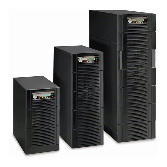
Three-phase UPS system
Power range: 10-50kVA
Specifications are subject to change without notice
Edition 01.02.2011
Advertisement
Chapters
Table of Contents

Related Manuals for Newave PowerScale


Summary of Contents for Newave PowerScale
-
Page 1: User Manual
PowerScale USER MANUAL PowerScale highlights at a glance Best in class efficiency Cost savings during the entire life-cycle(TCO) Low input harmonic distortion Cost saving during installation Input Power Factor near unity Cost savings during installation and the entire life- cycle(TCO) - Page 2 Switzerland www.newavenergy.com Subsidiaries Austria Hong Kong & China Spain Newave Österreich GmbH Newave Energy Hong Kong ltd Newave España SA Laxenburgerstrasse 252 Room 2506, West Tower, Shun Tak Centre Arturo Soria 329 1 D A-1230 Wien HK-168-200 Connaught Road Central ES-28033 Madrid Österreich...
- Page 3 ENVIRONMENTAL CONSIDERATIONS 1.1.5 DECLARATION OF SAFETY CONFORMITY AND CE MARKING 1.1.6 INQUIRIES SYSTEM DESCRIPTION 1.2.1 MECHANICAL CHARACTERISTICS POWERSCALE 10-15KVA CABINET A 1.2.2 MECHANICAL CHARACTERISTICS POWERSCALE 10-25KVA CABINET B 1.2.3 MECHANICAL CHARACTERISTICS POWERSCALE 30-50KVA CABINET C 1.2.4 GENERAL SYSTEM DESCRIPTION 1.2.5 QUALITY STANDARDS AND UPS CLASSIFICATION CODE 1.2.6...
- Page 4 RECOMMENDED CABLE SECTIONS & FUSE RATINGS 2.1.3 CONNECTION DIAGRAM POWERSCALE FRONT AND REAR VIEW 2.2.1 FRONT AND REAR VIEW OF POWERSCALE CABINET A 2.2.2 FRONT AND REAR VIEW OF POWERSCALE CABINET B 2.2.3 FRONT AND REAR VIEW OF POWERSCALE CABINET C BATTERY CONNECTIONS 2.3.1...
- Page 5 MODEM/ETHERNET CARD NEWAVEWATCH MANAGEMENT SOFTWARE 10 SECTION-10: TECHNICAL DATA SHEET 10.1 POWERSCALE SYSTEM DESCRIPTION 10.2 TECHNICAL CHARACTERISTICS 10.2.1 MECHANICAL CHARACTERISTICS POWERSCALE 10-15KVA CABINET A 10.2.2 MECHANICAL CHARACTERISTICS POWERSCALE 10-25KVA CABINET B 10.2.3 MECHANICAL CHARACTERISTICS POWERSCALE 30-50KVA CABINET C 10.3 INPUT CHARACTERISTICS 10.3.1...
- Page 6 Section-0 10.10 BATTERY AUTONOMIES 10.10.1 EXAMPLES OF BATTERY AUTONOMY AT FULL LOAD WITH STANDARD CABINETS AND STANDARD BATTERY CONFIGURATION 10.11 INSTALLATION PLANNING 10.11.1 HEAT DISSIPATION PER UPS RANGE WITH NON-LINEAR LOAD 10.12 WIRING AND BLOCK DIAGRAMS FOR ALL UPS FRAMES 10.12.1 TERMINAL CONNECTIONS OVERVIEW 10.12.2...
- Page 7 Section-0 FOREWORD The UPS System operates with mains, battery or bypass power. It contains components that carry high currents and voltages. The properly installed UPS System is grounded to earth and IP 20 rated against electrical shock and foreign objects. Installation and service have to be done by the manufacturer’s qualified technicians or their authorized service partners.
- Page 8 IEC 62040-3 (VFI-SS-111) standards. The POWERSCALE UPS features innovations that combine to deliver the industry’s best key values like: enhanced power performance, parallel capability and connectivity’s interaction.
-
Page 9: Table Of Contents
DECLARATION OF SAFETY CONFORMITY AND CE MARKING ..........4 1.1.6 INQUIRIES........................... 4 SYSTEM DESCRIPTION ........................5 1.2.1 MECHANICAL CHARACTERISTICS POWERSCALE 10-20KVA CABINET A......5 1.2.2 MECHANICAL CHARACTERISTICS POWERSCALE 10-25KVA CABINET B......5 1.2.3 MECHANICAL CHARACTERISTICS POWERSCALE 25-50KVA CABINET C......6 1.2.4... -
Page 10: Safety Instructions
Section-1 SAFETY INSTRUCTIONS 1.1.1 DESCRIPTION OF SYMBOLS USED IN THIS MANUAL WARNING! THERE IS DANGER OF AN ELECTRICAL IMPACT READ THE INFORMATION, IN ORDER TO AVOID EQUIPMENT NOTE! DAMAGES 1.1.2 SYMBOLS, CONTROLS, AND INDICATORS PROTECTIVE GROUNDING TERMINAL A terminal which must be connected to earth ground prior to making any other connection to the equipment. -
Page 11: Operator Precautions
USP System must adhere to the instructions in this manual. Any deviations from the instructions could be dangerous to the user or cause accidental load loss. NEWAVE SA DOES NOT TAKE ANY RESPONSIBILITY FOR DAMAGES CAUSED THROUGH WRONG MANIPULATIONS OF THE UPS SYSTEM. -
Page 12: Environmental Considerations
Section-1 1.1.4 ENVIRONMENTAL CONSIDERATIONS The UPS must be installed according to the recommendations in this manual. To operate the UPS at peak efficiency, your installation site should meet the environmental parameters outlined in this manual. Excessive amount of dust in the operating environment of UPS may cause damage or lead to malfunction. The UPS should be always protected from the outside weather and sunshine. -
Page 13: System Description
The product described in this manual is a transformerless Uninterruptible Power System (UPS). It is a true online, continuous duty, double conversion, solid state, three-phase system, providing conditioned and uninterruptible AC power to protect the customer’s load from all nine power failures. 1.2.1 MECHANICAL CHARACTERISTICS POWERSCALE 10-20KVA CABINET A PowerScale Cabinet A Power range... -
Page 14: Mechanical Characteristics Powerscale 25-50Kva Cabinet C
Section-1 1.2.3 MECHANICAL CHARACTERISTICS POWERSCALE 25-50KVA CABINET C PowerScale Cabinet C Max. Power connection Dimensions (WxHxD) 440x1400x910 (9Ah/28Ah) (9Ah/28Ah) 9Ah/28Ah 9Ah/28Ah Weight without battery 151/135 160/145 165/150 170/155 Weight with battery 144 blocks of 7/9Ah 48 blocks of 28Ah with standard packaging... -
Page 15: Feature : Flexible Battery Management (Fbm)
Feature : Flexible Battery Management (FBM) The Flexible Battery Management (FBM) has been designed in all NEWAVE UPS products with the goal to avoid the deterioration of battery age. The FBM – Key Features protect the battery from environmental negative impacts (high temperature and false manipulations) and avoid deterioration of battery life by advanced management of battery charging and preventive failure diagnostics. -
Page 16: Single/Parallel Configurations
1.2.6 SINGLE/PARALLEL CONFIGURATIONS Single UPS Configuration: Parallel UPS Configurations: It is possible to parallel a PowerScale UPS (up to 10 units) in order to increase power capacity or for power redundancy purpose. 1.2.7 WARRANTY The UPS supplied is warranted against defects in design, materials for a period of twelve (12) months from its original date of commissioning or fifteen (15) months from the date of original delivery, whatever comes first, unless agreed differently between Newave and the partner or customer. -
Page 17: Extended Warranty
The outside ’Tip&Tel’ ( "FRAGILE" and "ARROW") indicator should be intact if the equipment has been transported in the upright position. In case of rupture or suspect inform immediately: • The carrier and • NEWAVE SA. www.newavenergy.com 04-1206_S1_NW_OPMPS_10-50kVA_GB_110201.doc Page 9/20 Printed in Switzerland – Modifications reserved... -
Page 18: Unpacking
Section-1 Ensure that the received UPS corresponds to the material indicated in the delivery note. The packing container of the UPS protects it from mechanical and environmental damage. To increase its protection the UPS is wrapped with a plastic sheet. VISIBLE TRANSPORT DAMAGES MUST BE CLAIMED TO THE CARRIER IMMEDIATELY AFTER RECEIPT !! OTHER CLAIM FOR SHIPPING DAMAGE MUST BE FILED IMMEDIATELY TOO... -
Page 19: Nameplate
The battery life depends very much on the ambient temperature. A temperature range between +18° and +23°C will achieve the optimum battery life. If the UPS is delivered without batteries, NEWAVE is not responsible for any damage or malfunctioning caused to the UPS by incorrect wiring. -
Page 20: Storage Of Ups
Section-1 SEALED BATTERIES MUST NEVER BE STORED IN A DISCHARGED OR PARTIALLY DISCHARGED STATE. EXTREME TEMPERATURE, UNDER- AND OVERCHARGE AND OVERDISCHARGE WILL DESTROY BATTERIES! WARNING! 1.3.5.2 Storage of UPS If you plan to store the UPS prior to use, keep the UPS unpacked in a dry, clean and cool storage room with an ambient temperature between (+5 °C to +40°C) and humidity of less than 90%. -
Page 21: Positioning
Section-1 1.4.2.2 Positioning UPS : A minimum 200 mm rear space from the UPS to an obstruction is recommended for proper cooling as the air enters at bottom/front and exits at unit rear (see Fig. 1 and 2) External Battery : It’s recommended to install external battery cabinet(s) next to the UPS unit. The external battery is recommended to be placed on left hand side of the UPS unit. -
Page 22: Electrical Installation
Section-1 ELECTRICAL INSTALLATION The customer has to supply the wiring to connect the UPS to the local power source see Section 2, chapter 1.1. The electrical installation procedure is described in the following text. The installation inspection and initial start up of the UPS and extra battery cabinet must be carried out by a qualified service personnel such as a licensed service engineer from the manufacturer or from an agent authorised by the manufacturer. -
Page 23: Preparation For The Input Cabling
Section-1 1.5.1 PREPARATION FOR THE INPUT CABLING NOTE! Before proceeding read the chapter ELECTRICAL INSTALLATION (Section 1) and insure before starting connecting the cable to the UPS that: • Mains voltage (INPUT VOLTS) and frequency (FREQUENCY) correspond to the values indicated on the Nameplate of the UPS. -
Page 24: Single Input Feed
Section-1 1.5.1.2 Single Input Feed To achieve correct Input Cabling see Drawing Section 2, chapter 2.1.3 For single input feed connect the mains input cable to UPS Terminal Block according to the following table: MAINS INPUT CABLE UPS TERMINAL Phase L1 Phase L2 Phase L3 NEUTRAL... - Page 25 Section-1 For dual input feed connect the mains input cables to UPS Terminal according to following tables: MAINS INPUT CABLE UPS TERMINAL BYPASS INPUT CABLE UPS TERMINAL Rectifier Bypass Phase L1 Phase L1 Phase L2 Phase L2 Phase L3 Phase L3 NEUTRAL NEUTRAL EARTH...
-
Page 26: Preparation For The Output Cabling
Remove the terminal cover of the UPS. Connect the output power cable coming from the LV-Distribution Board to the terminals of the UPS as shown in drawing in Section-2, Paragraph 2.1.3 (Front view of the PowerScale) www.newavenergy.com 04-1206_S1_NW_OPMPS_10-50kVA_GB_110201.doc Page 18/20... - Page 27 Section-1 1.5.2 INSTALLATION CHECKLIST All packing materials and restraints have been removed from each cabinet. Each cabinet in the UPS system is placed in the installed location. All conduits and cables are properly routed to the UPS and auxiliary cabinets. All power cables are properly sized and terminated.
- Page 28 Section-1 This page left intentionally blank www.newavenergy.com 04-1206_S1_NW_OPMPS_10-50kVA_GB_110201.doc Page 20/20 Printed in Switzerland – Modifications reserved...
- Page 29 FRONT and REAR VIEW ......................4 2.2.1 FRONT AND REAR VIEW OF POWERSCALE CABINET A ..........4 2.2.1.1 Front and Rear View PowerScale 10-20kVA in Cabinet A and Connection Terminals..4 2.2.2 FRONT AND REAR VIEW OF POWERSCALE CABINET B ..........5 2.2.2.1 Front and Rear View PowerScale 10-25kVA in Cabinet B and Connection Terminals..5 2.2.3...
-
Page 30: Block Diagram
Section-2 BLOCK DIAGRAM 2.1.1 WIRING AND BLOCK DIAGRAMS The customer has to supply the wiring to connect the UPS to the local power source. The installation inspection and initial start up of the UPS and extra battery cabinet must be carried out by a qualified service personnel such as a licensed service engineer from the manufacturer or from an agent authorised by the manufacturer. -
Page 31: Connection Diagram Powerscale
Static Switch Mainten. Bypass Mainten. Bypass Frame Frame Cable D Cable D Load Load Figure 3.3: Block Diagram POWERSCALE from 10-50 kVA STANDARD VERSION (SINGLE INPUT FEED) Power Cable A Cable E Fuse A Cable D Fuse E (IEC 60950-1:2001) -
Page 32: Front And Rear View
Section-2 FRONT and REAR VIEW 2.2.1 FRONT AND REAR VIEW OF POWERSCALE CABINET A 2.2.1.1 Front and Rear View PowerScale 10-20kVA in Cabinet A and Connection Terminals FRONT VIEW REAR VIEW 9/10 Power Management Display (PMD) of POWERSCALE PC Interface (Slot 1 Option) JD1/RS232 Sub D9/female Interface (UPS system to computer) (see section 3 / 1.1) -
Page 33: Front And Rear View Of Powerscale Cabinet B
Section-2 2.2.2 FRONT AND REAR VIEW OF POWERSCALE CABINET B 2.2.2.1 Front and Rear View PowerScale 10-25kVA in Cabinet B and Connection Terminals FRONT VIEW REAR VIEW 9/10 15 16 Power Management Display (PMD) of POWERSCALE PC Interface (Slot 1 Option) 13 14 JD1/RS232 Sub D9/female Interface (UPS system to computer) (see section 3 / 1.1) -
Page 34: Front And Rear View Of Powerscale Cabinet C
Section-2 2.2.3 FRONT AND REAR VIEW OF POWERSCALE CABINET C 2.2.3.1 Front and Rear View PowerScale 25-50kVA in Cabinet C and Connection Terminals Front Front view Rear open closed view 9/10 Power Management Display (PMD) of POWERSCALE PC Interface (Slot 1 Option) 12/13 JD1/RS232 Sub D9/female Interface (UPS system to computer) (see section 3 / 1.1) -
Page 35: Battery Connections
2.3.1 BATTERY BANKS CABINETS A & B AND EXTERNAL BATTERY PowerScale has additional battery enclosure. In the drawing below the Battery enclosures are shown. NOTE: Within the cabinets A & B in only 7/9Ah batteries are allowed (16-48 blocks), in Cabinet C also 28Ah batteries are allowed Cabinet A (max. -
Page 36: Examples Of Battery Autonomy At Full Load With Standard Battery Cabinets And Standard Battery Configuration
Section-2 2.3.1.1 Examples of Battery Autonomy at full load with standard battery cabinets and standard battery configuration Powerscale 10kVA, 9kW Load Power Autonomy (min) 7Ah batt 9Ah batt 7Ah batt 9Ah batt 7Ah batt 9Ah batt 1 x 24 1 x 20... - Page 37 Section-2 Powerscale 20kVA, 18kW Load Power 12kW 16kW 18kW Autonomy (min) 7Ah batt 9Ah batt 7Ah batt 9Ah batt 7Ah batt 9Ah batt 7Ah batt 9Ah batt 1 x 48 1 x 34 1 x 24 1 x 48 1 x 32...
- Page 38 Section-2 Powerscale 30kVA, 27kW Load Power 16kW 20kW 24kW 27kW Autonomy (min) 7Ah batt 9Ah batt 28Ah batt 7Ah batt 9Ah batt 28Ah batt 7Ah batt 9Ah batt 28Ah batt 7Ah batt 9Ah batt 28Ah batt 2 x 34 1 x 40...
- Page 39 Section-2 Powerscale 50kVA, 40kW Load Power 30kW 35kW 40kW 45kW Autonomy (min) 7Ah batt 9Ah batt 28Ah batt 7Ah batt 9Ah batt 28Ah batt 7Ah batt 9Ah batt 28Ah batt 7Ah batt 9Ah batt 28Ah batt 3 x 40 2 x 40...
-
Page 40: Connection Of External Battery For Powerscale
The UPS and the external battery are voltage-free To verify the complete shut down of the PowerScale perform following steps: 1) Make sure that the fuses feeding the UPS in the input Distribution Board are all open and no power is fed to the UPS. - Page 41 Section-2 Fig. 3.2.4 UPS Configuration with external battery If the UPS has to be configured with external batteries, the internal battery link to the position of F1 (Battery Fuse) has to be replaced by the short Links delivered separately at the bag of the accessories. The 3 links has to be installed between the following points.
- Page 42 Section-2 This page left intentionally blank www.newavenergy.com Page 14/14 04-1206_S2_NW_OPMPS_10-50kVA_GB_110201.doc Printed in Switzerland – Modifications reserved...
- Page 43 Section-3 SECTION-3 INTERFACING .............................2 3.1.1 SMART PORT JD1 (SERIAL RS 232 / SUB D9 / FEMALE) AND USB PORT ....2 3.1.2 CUSTOMER INTERFACE AND DRY PORTS (TERMINALS X1 STANDARD)....3 3.1.2.1 Input Interfaces Terminal block X1.................3 3.1.2.2 Output Interfaces Terminal blocks X1 ((option relay card/slot)) ........3 3.1.3 JR1 / RS485 INTERFACE FOR MULTIDROP ..............4 www.newavenergy.com...
-
Page 44: Interfacing
Section-3 3.1 INTERFACING Each UPS is provided with communication port and a communication card, which provides system information STANDARD ITEMS RS232 on Sub-D9 port For monitoring and integration in network management 1 Remote Shut down [EMERGENCY OFF (Normally closed)] 1 GEN-ON (Normally open) Customer Interfaces : 1 Programmable Customer’s Inputs (Normally open) Inputs DRY PORT... -
Page 45: Customer Interface And Dry Ports (Terminals X1 Standard)
Section-3 3.1.2 CUSTOMER INTERFACE AND DRY PORTS (TERMINALS X1 STANDARD) All the Input and Output interfaces are connected to Phoenix terminals (cable 0.5 mm2) 3.1.2.1 Input Interfaces Terminal block X1 Connection of Remote Shut down facilities, Generator Operation, Customers specials (see Section 9, chapter 1.2 OPTIONS) 3.1.2.2 Output Interfaces Terminal blocks X1 ((option relay card/slot)) Provision of signals for the automatic and orderly shutdown of servers, AS400 or Automation building systems... -
Page 46: Jr1 / Rs485 Interface For Multidrop
Slot 2 Slot 1 Example : Distribution Interfaces Slot 2 Slot 1 Power Management Display (PMD) of POWERSCALE PC Interface (Slot 1 Option) JD1/RS232 Sub D9/female Interface (UPS system to computer) (see section 3 / 1.1) Customer Inputs Customer interface on Phoenix Terminals (Slot 1 Option): X2= Potential free contacts (detail see Section 3 / 1.2 ) - Page 47 Section-4 CONTENTS SECTION-4 OPERATION ..........................2 4.1.1 COMMISSIONING ........................2 4.1.2 CONTROL PANEL ........................2 4.1.2.1 Power Management Display (PMD) ................2 4.1.2.2 LED Indicators........................3 4.1.2.3 Keys ..........................3 4.1.2.4 ON/OFF Start-up and Shutdown Buttons...............3 4.1.3 DESCRIPTION OF THE LCD ....................4 4.1.3.1 Status Screens.......................4 4.1.3.2 Main Menu Screen ......................4 4.1.3.3 Event Log Screen......................5...
-
Page 48: Operation
4.1.1 COMMISSIONING The PowerScale is a high quality electronic machine, that must be commissioned by a fully trained and authorized NEWAVE field service engineer before being put into use. The commissioning of the UPS involves the connection of the UPS and battery, the checking of the electrical installation and operating environment of the UPS, the controlled start-up and testing of the UPS and customer training. -
Page 49: Led Indicators
Section-4 4.1.2.2 LED Indicators The mimic diagram serves to indicate the general status of the UPS. The LED-indicators show the power flow status and in the event of mains failure or load transfer from inverter to bypass and vice-versa. The corresponding LED-indicators will change colours from green (normal) to red (warning). -
Page 50: Description Of The Lcd
Section-4 4.1.3 DESCRIPTION OF THE LCD 4.1.3.1 Status Screens DESCRIPTION LCD-DISPLAY Load is protected by UPS power. LOAD Load is supplied by inverter (Normal Operation) PROTECTED and the batteries are connected and o.k. Load is not protected by UPS power. LOAD Load is supplied by mains power (load on NOT PROTECTED... -
Page 51: Event Log Screen
Section-4 4.1.3.3 Event Log Screen DESCRIPTION LCD-DISPLAY Logging Control; a log of the last 99 events is 05-10-00 14-38-59 stored in the Power Management Display. LOAD TO INV. Every stored event is identified with a sequential 05-10-00 14-38-56 number and time stamp. LOAD TO BYP. -
Page 52: Ups Data
Section-4 4.1.3.6 UPS Data DESCRIPTION LCD-DISPLAY UPS SERIAL NUMBER These general UPS Data are installed at the NW-nnnnn manufacturing plant DATE OF MANUFACTURE Manufacturing date 15-01-2009 EPROM Version EPROM VERSION V-000 Actual Date and Time DATE TIME dd-mm-yyyy hh:mm:ss 4.1.3.7 Set-Up User DESCRIPTION LCD-DISPLAY SET LANGUAGE... -
Page 53: Operating Modes
Section-4 4.1.4 OPERATING MODES 4.1.4.1 Mode "ON LINE" (INVERTER MODE) The ON-LINE-Mode is the UPS-Operating Mode in which the load is supplied through the RECTIFIER and INVERTER. LED Indicator Colour LINE 1 Green LINE 2 Green BYPASS INVERTER Green BATTERY Green Using the control panel (see figure 1.1), the UPS can easily be transferred to the ON-LINE-Mode. -
Page 54: Maintenance Bypass" - Mode
Section-4 4.1.4.3 "MAINTENANCE BYPASS" - Mode The Maintenance Bypass Mode is performed by means of the IA1 BYPASS SWITCH on the rear of the UPS: POSITION OF EFFECT SWITCH Bypass-Switch Closed (Load supplied directly from mains) LCD-indication: “MANUAL BYP IS CLOSED” LED Indicators will indicate as shown in table below. - Page 55 Section-5 CONTENTS SECTION-5 OPERATION - PROCEDURES....................2 5.1.1 START-UP PROCEDURE ....................2 5.1.2 SHUTDOWN PROCEDURE ....................4 5.1.3 LOAD TRANSFER: FROM INVERTER OPERATION TO MAINTENANCE BYPASS..5 5.1.4 LOAD TRANSFER: FROM MAINTENANCE BYPASS TO INVERTER OPERATIONS ..6 www.newavenergy.com 04-1206_S5_NW_OPMPS_10-50kVA_GB_101213.doc Page 1/6 Printed in Switzerland – Modifications reserved...
-
Page 56: Operation - Procedures
Make sure that the internal battery enclosure fuses and/or the external battery cabinets fuses are open. Bypass fuses F2 and rectifier fuses F1 are inserted. Start up procedure of PowerScale: Insert fuses for the supply of UPS-System in the Input Distribution and check the input phase rotation. - Page 57 On control panel go to Menu COMMANDS, choose command “LOAD TO INVERTER” and transfer the load to inverter. On all LCD’s: “LOAD PROTECTED” will appear Check the output Voltages and Currents once again. THE LOAD IS NOW PROTECTED BY THE POWERSCALE www.newavenergy.com 04-1206_S5_NW_OPMPS_10-50kVA_GB_101213.doc Page 3/6...
-
Page 58: Shutdown Procedure
AUTHORIZED BY THE MANUFACTURER. WARNING! The POWERSCALE may be shutdown completely, if the load does not need input power for an extended period of time. It may be switched to Maintenance Bypass Mode for service or maintenance purposes, or transferred to the OFF- LINE Mode (ECO-Mode), if the load does not need the highest degree of protection. -
Page 59: Load Transfer: From Inverter Operation To Maintenance Bypass
Situation of UPS-System before starting the Transfer Procedure to Maintenance Bypass: The load is protected by PowerScale running in normal operation. (The UPS is operating on inverter). Using LCD panel, select the COMMANDS menu, choose command “LOAD TO BYPASS” and transfer the load to mains. -
Page 60: Load Transfer: From Maintenance Bypass To Inverter Operations
Section-5 5.1.4 LOAD TRANSFER: FROM MAINTENANCE BYPASS TO INVERTER OPERATIONS This procedure describes the sequence of operations to be done in order to restart the UPS and restore ON-LINE mode (Load on Inverter). THE OPERATIONS DESCRIBED IN THIS CHAPTER MUST BE PERFORMED BY A SERVICE ENGINEER FROM THE MANUFACTURER OR FROM A AGENT AUTHORIZED BY THE MANUFACTURER. - Page 61 Section-6 CONTENTS SECTION-6 MULTI-CABINET CONFIGURATION ..................2 6.1.1 CONCEPT OF MULTI-CABINET CONFIGURATION ............2 6.1.2 INSTALLATION INSTRUCTIONS ..................3 6.1.2.1 Introduction ........................3 6.1.2.2 Paralleling of UPS-Cabinets...................3 6.1.2.2.1 Connection of Parallel Communication Cables (BUS-lines) ........3 6.1.2.2.2 Parallel Adapter and DIP-Switch SW2-2 ..............4 6.1.2.3 DIP-Switch SW1-9 Settings ...................4 6.1.2.4 DIP Switch SW1-9......................4 6.1.2.5...
-
Page 62: Multi-Cabinet Configuration
IMPORTANT: The BYPASS MODE (ECO-MODE) function of a parallel systems is the same as in single units of POWERSCALE. If in a parallel UPS system the load is transferred to the BYPASS (load on mains) and if the mains fails, the UPS’s will all be automatically transferred to inverter within 5msec. -
Page 63: Installation Instructions
Section-6 6.1.2 INSTALLATION INSTRUCTIONS 6.1.2.1 Introduction THE OPERATIONS DESCRIBED IN THIS CHAPTER MUST BE PERFORMED BY A SERVICE ENGINEER FROM THE MANUFACTURER OR FROM A AGENT AUTHORIZED BY THE MANUFACTURER. WARNING! NOTE: IN ORDER TO ACHIEVE EQUAL LOAD SHARING BETWEEN THE UPS-CABINETS, THE INPUT CABLE LENGTHS FROM THE INPUT DISTRIBUTION BOARD TO THE UPS AND FROM THE OUTPUT CABLE TO THE OUTPUT DISTRIBUTION BOARD SHOULD BE THE SAME RESPECTIVELY. -
Page 64: Parallel Adapter And Dip-Switch Sw2-2
6.1.2.4 DIP Switch SW1-9 The DIP Switch SW1-9 is located on every Cabinet (POWERSCALE) With this switch it is possible to determine the “position of an POWERSCALE - Cabinet” in a Multi-Cabinet Chain. Define each POWERSCALE - Cabinet in a Multi-Cabinet Chain as: 1. -
Page 65: On/Off - Main Buttons
6.1.2.8 ECO-MODE (BYPASS MODE) in Parallel Systems The Eco-Mode function in a Parallel System is the same as in Single Systems. If in a PowerScale Parallel System the load is supplied by the mains(load on mains) and in the event of mains failure, all UPS’s will automatically transfer the load back to the inverters with 5msec. -
Page 66: Commissioning Of Parallel Configuration
Manual; The parallel communication cables have been connected correctly according to Paragraph 6.1.2.2.1 All the DIP Switches for POWERSCALE - Cabinets been set correctly according to Paragraphs 6.1.2.2.2 and 6.1.2.4 All the internal (if any) and /or external battery cabinets/racks have been connected correctly The start-up of a parallel Configuration may be performed in analogy to the start-up procedures for a single PowerScale - Cabinet described in Paragraph 1.1 of section 5. - Page 67 Section-7 CONTENTS SECTION-7 MAINTENANCE ...........................2 7.1.1 INTRODUCTION ........................2 7.1.2 USER RESPONSIBILITIES ....................2 7.1.3 ROUTINE MAINTENANCE ....................2 7.1.4 BATTERY TEST........................2 7.1.5 BATTERY MAINTENANCE....................3 7.1.6 BATTERY DISPOSAL AND RECYCLING ................3 www.newavenergy.com 04-1206_S7_NW_OPMPS_10-50kVA_GB_110201.doc Page 1/4 Printed in Switzerland – Modifications reserved...
- Page 68 SERVICE ENGINEER FROM THE MANUFACTURER OR FROM A AGENT AUTHORIZED BY THE MANUFACTURER. WARNING! To ensure an optimum operation of the POWERSCALE and a continuous and efficient protection of the connected load it is recommended to check the batteries every 6 months, depending on the ambiance temperature. 7.1.2...
- Page 69 Section-7 7.1.5 BATTERY MAINTENANCE The battery maintenance shall be performed by a service engineer from the manufacturer or from an agent authorized by the manufacturer. 7.1.6 BATTERY DISPOSAL AND RECYCLING Batteries contain dangerous substances that will harm the environment if thrown away.
- Page 70 Section-7 This page left intentionally blank www.newavenergy.com 04-1206_S7_NW_OPMPS_10-50kVA_GB_110201.doc Page 4/4 Printed in Switzerland – Modifications reserved...
- Page 71 Section-8 CONTENTS SECTION-8 TROUBLESHOOTING .........................2 8.1.1 ALARMS..........................2 8.1.2 MENU, COMMANDS, EVENT LOG AND MEASUREMENTS ..........2 8.1.3 FAULT IDENTIFICATION AND RECTIFICATION ..............2 www.newavenergy.com 04-1206_S8_NW_OPMPS_10-50kVA_GB_110201.doc Page 1/2 Printed in Switzerland – Modifications reserved...
-
Page 72: Troubleshooting
Section-8 TROUBLESHOOTING 8.1.1 ALARMS In the event of an alarm condition the red LED-Indicator “Alarm” and the audible alarm will turn on. In this case proceed as follows: Silence the audible alarm by pressing the button "Reset". Identify the cause of the alarm condition by means of the EVENT LOG in the MAIN menu. (see Section-4, Paragraph 4.1.3.2) In case of doubts please contact the nearest Service centre. - Page 73 Section-9 CONTENTS SECTION-9 OPTIONS .............................2 9.1.1 INTRODUCTION ........................2 9.1.2 REMOTE SHUT DOWN ......................2 9.1.3 GENERATOR ON FACILITIES .....................3 9.1.4 WAVEMON SHUTDOWN AND MANAGEMENTSOFTWARE..........3 9.1.4.1 Why is UPS Management important? ................3 9.1.4.2 WAVEMON Shutdown and Monitoring Software ............3 9.1.5 SNMP CARD/ADAPTER FOR NETWORK MANAGEMENT /REMOTE MONITORING ..5 9.1.6 MODEM/ETHERNET CARD / NEWAVEWATCH™...
-
Page 74: Options
Usually the shut down procedure is disabled and it should be activated by a Hardware Code on “Setup Service” menu”. Please contact your distributor to enable this operation. The remote shutdown on terminal port X1/7.. X1/8 is located on the PowerScale frame on communication card with terminal blocks X1. See Section-3, Paragraph 3.1.2.2... -
Page 75: Generator On Facilities
The Generator ON facility must use a normally open contact that closes to indicate that a generator is running and supplying input power to UPS. It is located at the bottom of the PowerScale frame on communication card with terminal blocks X1. See Section-3, Paragraph 3.1.2.2... - Page 76 Section-9 The dry port X2 with voltage-free contacts may also be used for automatic shutdown in connection with WAVEMON Software. It is necessary to provide a cable of 0.5 mm2 to connect Terminals X2 of the UPS and the serial port of the server. Figure 1.4.2.
-
Page 77: Snmp Card/Adapter For Network Management /Remote Monitoring
Maintenance on a redundant unit may be executed without annoyance to the management system (supervisor). In order to be managed, a NEWAVE UPS can be integrated into a network in two ways: 1. By means of the server which is being powered by the UPS and is integrated in the network. In most of the cases the server is used as sub-agent and you only need the PMC-Software without any SNMP Adapter. -
Page 78: Modem/Ethernet Card / Newavewatch™ Management Software
Figure 1.5.1 External SNMP Adapter The Internal SNMP-Card can be inserted into an appropriate extension slot of the PowerScale. This adapter communicates via the serial port of the UPS and makes a direct multiple server shut down possible without additional SNMP management software. - Page 79 Section-9 Comprehensive Management System • Reception and management of alarm calls from UPS • Storage of UPS Data in a database exportable in a CVS-format for easy handling in Excel • Unlimited number of UPS that can be managed • User administration with passwords and permission-level •...
-
Page 80: 04-1206_S9_Nw_Opmps_10-50Kva_Gb_110201.Doc
Section-9 This page left intentionally blank www.newavenergy.com 04-1206_S9_NW_OPMPS_10-50kVA_GB_110201.doc Page 8/8 Printed in Switzerland – Modifications reserved... -
Page 81: Technical Specifications
PowerScale Technical Specifications PowerScale highlights at a glance Best in class efficiency Cost savings during the entire life-cycle(TCO) Low input harmonic distortion Cost saving during installation Input Power Factor near unity Cost savings during installation and the entire life- cycle(TCO) - Page 82 Section-10 TABLE OF CONTENTS 10.1 POWERSCALE SYSTEM DESCRIPTION ....................3 10.2 TECHNICAL CHARACTERISTICS ......................4 10.2.1 MECHANICAL CHARACTERISTICS POWERSCALE 10-20kVA Cabinet A.........4 10.2.2 MECHANICAL CHARACTERISTICS POWERSCALE 10-25kVA Cabinet B.........4 10.2.3 MECHANICAL CHARACTERISTICS POWERSCALE 25-50kVA Cabinet C.........5 10.3 INPUT CHARACTERISTICS ........................5 10.3.1 GRAPH: INPUT PF VERSUS % LOAD....................6 10.3.2...
-
Page 83: Powerscale System Description
The most demanding IT infrastructures start with low power before achieving its full capacity. It is in this case essential to be able to recover the missing power requirement without risk for the applied load. POWERSCALE allows for system upgrades to meet the highest level of availability interruption free and without a temporary transfer the load to row mains (by-pass). -
Page 84: Technical Characteristics
Section-10 10.2 TECHNICAL CHARACTERISTICS 10.2.1 MECHANICAL CHARACTERISTICS POWERSCALE 10-20kVA Cabinet A PowerScale Cabinet A Power range Dimensions (WxHxD) 345x720x710 Weight without battery Weight with battery with 48 block of 7Ah with standard packaging Colour Graphite grey (RAL 7024) 10.2.2 MECHANICAL CHARACTERISTICS POWERSCALE 10-25kVA Cabinet B PowerScale Cabinet B Max. -
Page 85: Mechanical Characteristics Powerscale 25-50Kva Cabinet C
Section-10 10.2.3 MECHANICAL CHARACTERISTICS POWERSCALE 25-50kVA Cabinet C PowerScale Cabinet C Max. Power connection Dimensions (WxHxD) 440x1400x910 (9Ah/28Ah) (9Ah/28Ah) 9Ah/28Ah 9Ah/28Ah Weight without battery 151/135 160/145 165/150 170/155 Weight with battery 144 blocks of 7/9Ah 48 blocks of 28Ah with standard packaging... -
Page 86: Graph: Input Pf Versus % Load
Section-10 10.3.1 GRAPH: INPUT PF VERSUS % LOAD Input Power factor (Leading) 0.985 0.99 0.99 0.96 Load % 10.3.2 GRAPH: INPUT DISTORTION THDi VERSUS % LOAD Input Current Distortion THDi Load % NOTE: Depending on power ratings www.newavenergy.com 04-1206_S10_NW_TDSPS_10-50kVA_GB_110201.DOC Page 6/19 Printed in Switzerland –... -
Page 87: Battery Characteristics
Section-10 10.4 BATTERY CHARACTERISTICS 10kVA 15kVA 20kVA 25kVA 30kVA 40kVA 50kVA UPS Range Cabinet Type Min/Max number of 12V 16-50(*) 20-50(*) 24-50(*) 20-50(*) 24-50(*) 16-50(*) 18-50(*) 30-50(*) Battery Blocks per string Maximum Battery Charger Current Battery Charging Curve Ripple free ; IU (DIN 41773) Temperature compensation Standard (temp. -
Page 88: Output Characteristics
Section-10 10.5 OUTPUT CHARACTERISTICS UPS Model PS 10 PS 15 PS 20 PS 25 PS 30 PS 40 PS 50 Output Rated Power Output Rated Power 13.5 22.5 Output Current In @ PF0.9 (400VAC) 14.4 21.7 28.9 36.1 43.3 57.7 72.2 Output Current In @ PF1 (400VAC) 13.0... -
Page 89: Environmental Characteristics
Section-10 10.6 ENVIRONMENTAL CHARACTERISTICS UPS range 10kVA 15kVA 20kVA 25kVA 30kVA 40kVA 50kVA Audible Noise with 55/49 55/49 57/49 57/49 58/50 59/50 59/50 100% / 50% Load Operation temperature °C 0 – 40 Ambient Temperature °C for Batteries 20 – 25 (recommended) Storage Temperature °C... -
Page 90: Communication
INVERTER or load transfer from INVERTER to BYPASS and vice-versa and finally it serves for the DIAGNOSIS (SERVICE MODE) for adjustments and testing (for more details see the USER MANUAL of POWERSCALE). www.newavenergy.com 04-1206_S10_NW_TDSPS_10-50kVA_GB_110201.DOC... -
Page 91: Customer Interfaces: Terminals X1 Standard
Section-10 Power Management Display (PMD) of POWERSCALE 10.8.4 CUSTOMER INTERFACES: Terminals X1 Standard 10.8.5 CUSTOMER INPUTS DRY PORTs: Terminal block X1 Connection of Remote Shut down facilities, Generator Operation, Customers specials (see UM Section 9 / OPTIONS) 10.8.6 CUSTOMER OUTPUTS DRY PORTs : Terminal blocks X1 (optional relay slot card) Provision of signals for the automatic and orderly shutdown of servers, AS400 or Automation building systems All voltage free contacts are rated 60 VAC max. -
Page 92: Options
Section-10 10.9 OPTIONS - Modem/Ethernet card or Modem/GSM card for Newavewatch Management Software - SNMP card and WaveMon Management Software , Modbus Protocol, USB - External Battery Cabinets - Parallel kit - In/output Transformer for special voltages - Back-feed protection - Temp. -
Page 93: Battery Autonomies
Section-10 10.10 BATTERY AUTONOMIES 10.10.1 EXAMPLES OF BATTERY AUTONOMY AT FULL LOAD WITH STANDARD CABINETS AND STANDARD BATTERY CONFIGURATION Powerscale 10kVA, 9kW Load Power Autonomy (min) 7Ah batt 9Ah batt 7Ah batt 9Ah batt 7Ah batt 9Ah batt 1 x 24... - Page 94 Section-10 Powerscale 20kVA, 18kW Load Power 12kW 16kW 18kW Autonomy (min) 7Ah batt 9Ah batt 7Ah batt 9Ah batt 7Ah batt 9Ah batt 7Ah batt 9Ah batt 1 x 48 1 x 34 1 x 24 1 x 48 1 x 32...
- Page 95 Section-10 Powerscale 30kVA, 27kW Load Power 16kW 20kW 24kW 27kW Autonomy (min) 7Ah batt 9Ah batt 28Ah batt 7Ah batt 9Ah batt 28Ah batt 7Ah batt 9Ah batt 28Ah batt 7Ah batt 9Ah batt 28Ah batt 2 x 34 1 x 40...
- Page 96 Section-10 Powerscale 50kVA, 40kW Load Power 30kW 35kW 40kW 45kW Autonomy (min) 7Ah batt 9Ah batt 28Ah batt 7Ah batt 9Ah batt 28Ah batt 7Ah batt 9Ah batt 28Ah batt 7Ah batt 9Ah batt 28Ah batt 3 x 40 2 x 40...
-
Page 97: Installation Planning
Section-10 10.11 INSTALLATION PLANNING Clearances Minimum 200 mm 900 mm Battery Cabinet Frames Frames Figure 1: UPS space recommendation Figure 2 : UPS + Battery space recommendation UPS Frame type Cabinet A Cabinet B Cabinet C CBATT-C Dimensions (WxHxD) mm 345x720x710 345x1045x710 440x1400x910... -
Page 98: Wiring And Block Diagrams For All Ups Frames
Section-10 10.12 WIRING AND BLOCK DIAGRAMS FOR ALL UPS FRAMES The customer has to supply the wiring to connect the UPS to the local power source. The installation inspection and initial start up of the UPS and extra battery cabinet must be carried out by a qualified service personnel such as a licensed service engineer from the manufacturer or from an agent authorised by the manufacturer. -
Page 99: Input Feed Ratings
Static Switch Mainten. Bypass Mainten. Bypass Frame Frame Cable D Cable D Load Load Figure 3.3: Block Diagram POWERSCALE from 10-50 kVA STANDARD VERSION (SINGLE INPUT FEED) Power Cable A Cable E Fuse A Cable D Fuse E (IEC 60950-1:2001)
Need help?
Do you have a question about the PowerScale and is the answer not in the manual?
Questions and answers