
Related Manuals for Firepower FP-200


Summary of Contents for Firepower FP-200
- Page 1 FP-200 and FP-260 MIG Welding System Instruction Manual FORM NO. 0056-1840 EFFECTIVE August 2001 Safety and Operating Instructions For Your Safety . . . PLEASE READ CAREFULLY!
-
Page 2: Table Of Contents
Firepower Limited Warranty ........ -
Page 3: Introduction
SAFETY INFORMATION The following safety information is provided to you as a guideline. Use it to operate your new Firepower Welding System under the safest possible conditions. Any equipment that uses electrical power is potentially dangerous to use when the safety or safe handling instructions are not known and/or are not followed. -
Page 4: Safety Instructions
3. NEVER look at the arc without proper protection to the eyes. 4. Thoroughly clean metal of rust or paint to avoid producing harmful fumes. Parts degreased with a solvent must dry before welding. 5. NEVER weld on metals or coated metals containing zinc, mercury, chromium, graphite, lead, cadmium or beryllium unless the operator and the people standing in the same area use an air-supplied respirator. -
Page 5: Safety Symbols
3. People with pace-makers or hearing aides should keep far from the power source. In particular cases, special protection measures may be required. Reduce interference by following these suggestions: 1. If there is interference in the power source line, mount an E.M.T. filter between the power supply and the power source. -
Page 6: Protective Welding Gasses
ELECTRIC SHOCK CAN KILL! Reduce the risk of death or serious injury from shock. Read, understand and follow the following safety instructions. Additionally, make certain that anyone else who uses this welding equipment, or who is a bystander in the welding area, understands and fol- lows these safety instructions as well. -
Page 7: Health Hazards
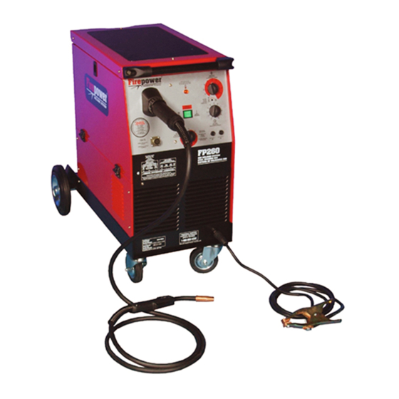
WELDER SPECIFICATIONS Your new Firepower Wire MIG (GMAW) and Flux Core (FCAW) Wire Welding System is designed for mainte- nance and sheet metal fabrication. The unit consists of a single-phase power transformer power source, arc stabilizer, rectifier and heavy-duty wire feed system. -
Page 8: Welder Operating Characteristics
MIG Gun ........10 foot FIREPOWER ®... -
Page 9: Mig Gun Specifications
MIG Gun ........10 foot FIREPOWER ®... -
Page 10: Power Source Connection
POWER SOURCE CONNECTION Power Requirements This welder is designed to operate on a properly grounded 230 volt, 60 HZ, single-phase alternating current (AC) power source fused with a 50 amp time-delayed fuse or circuit breaker. (Please consult local codes for proper plug and receptacle applications.) A qualified electrician should verify the ACTUAL VOLTAGE at the receptacle into which the welder will be plugged and confirm that the receptacle is properly grounded. -
Page 11: Flux Core (Fcaw) And Mig (Gmaw) Welding
grasp it with pliers so that it cannot exit from the spool. If necessary, straighten it before inserting it in the wire input guide. Insert the wire on the lower roll and in the torch liner. Keep the torch straight. When feeding a new wire through the liner, make sure the wire is cut cleanly (no burrs or angles) and that at least 2”... -
Page 12: Advantages Of Flux Core (Fcaw) Welding
Note that each roll has two grooves, one is marked “.035/0.9mm” and the other is marked “.030/0.8mm”. 5. This unit comes with a genuine FIREPOWER regulator and requires adjustment of the flow of shielding gas. Figure 4: Polarity Preparation for Welding with Gas Advantages of MIG (GMAW) Welding 1. -
Page 13: Mig Gun
DO NOT use the cylinder if you find oil, grease or damaged parts. Inform your gas supplier of this condition immediately. Regulator Gas Flow Information Before using regulator, read instructions thoroughly. For general, small diameter wire MIG welding the regulator setting is from 15-40 CFH. Example: .030” wire using 75/25 Argon/CO2 mix gas on 15 gauge sheet metal, gas flow from regulator should be set at 25 CFH. -
Page 14: Spot Welding
Spot welding is possible by replacing the welding nozzle with a spot welding nozzle. You can buy the spot welding nozzle from any supplier of Firepower Welding Systems. Spot welding can be performed on carbon steel sheets of up to 18 gauge thickness. -
Page 15: Additional Safety Information
ADDITIONAL SAFETY INFORMATION Make sure you read and understand all of the information and instructions contained in this manual BEFORE proceeding. The National Electrical Code, Occupational Safety and Health Act (OSHA) regulations, local industrial codes and local inspection requirements also provide a basis for equipment installation, use and service. For additional information concerning welding safety, refer to the following standards and comply with them as applicable. -
Page 16: Troubleshooting Information
TROUBLESHOOTING INFORMATION Use this chart to assist you in resolving common problems you may encounter. These are not all of the possible solutions. ROBLEM OSSIBLE AUSE EMEDY 1. Dirty, porous or brittle weld. Plugged welding nozzle. Clean or replace welding nozzle. 2. -
Page 17: General Operating Tips
GENERAL OPERATING TIPS Contact tips and nozzles should be cleaned frequently. Spatter buildup may cause bridging between nozzle and tip. This could cause electrical shorting between the nozzle and workpiece as well as poor or improper gas flow. Regularly inspect the conductor tube, handle, cable hose and other parts of the Mig-Gun for abrasion, cuts or undue wear. -
Page 18: Troubleshooting Guide For Fp-300 Mig Gun
TROUBLESHOOTING GUIDE FOR FP-300 MIG GUN ROBLEM OSSIBLE AUSE EMEDY 1. Wire feed inconsistent or not smooth. Loose contact tip or diffuser. Tighten contact tip and diffuser plier- tight. Excessively worn contact tip. Spatter Replace contact tip. buildup on end of contact tip. Clean or replace contact tip. -
Page 23: Firepower Limited Warranty
Notwithstanding the foregoing, • Firepower oxygen / acetylene products will be covered by a two-year product replacement warranty • Firepower plasma cutting equipment will be covered by a one-year (parts & labor) warranty. • Firepower electric welding machines will be covered by the Firepower 5-2-1 limited warranty. - Page 24 LIMITED WARRANTY CLAIM METHOD: To make a claim under this warranty, Purchaser must notify Seller of the details of such claim within thirty days of discovering a defect in material or work- manship. If the claim is covered by this warranty, Seller will direct Purchaser to return the product to an authorized warranty repair center.
Need help?
Do you have a question about the FP-200 and is the answer not in the manual?
Questions and answers