Table of Contents
Advertisement
Advertisement
Table of Contents

Related Manuals for Eaton 5P 650i


Summary of Contents for Eaton 5P 650i
-
Page 1: Tower Models
Tower models 5P 650i 5P 850i 5P 1150i 5P 1550i 1U Rack models 5P 650i R 5P 850i R 5P 1150i R 5P 1550i R Copyright © 2013 EATON All rights reserved. Service and support: Call your local service representative... -
Page 2: Special Symbols
Flickers emission: IEC 61000-3-3 edition 2: 2008 VCCI Notice The EC Declaration of Conformity is available upon request for products with a CE mark. For copies of the EC Declaration of Conformity, contact Eaton Power Quality or check Eaton website: www.powerquality.eaton.com Special Symbols... -
Page 3: Table Of Contents
Contents 1. Introduction ..................4 1.1 Environmental protection ....................4 2. Presentation ..................5 2.1 Standard installations ......................5 2.2 Tower rear panels ......................6 2.3 Rack rear panels ........................7 2.4 Control panel ........................8 2.5 LCD description .........................9 2.6 Display functions ......................10 2.7 User settings ........................ -
Page 4: Introduction
Before installing 5P , please read the booklet presenting the safety instructions. Then follow the instructions in this manual. To discover the entire range of EATON products and the options available for the 5P range, we invite you to visit our web site at www.eaton.com/powerquality or contact your EATON representative. -
Page 5: Presentation
Rack models Description Weights (kg/lb) Dimensions (mm/inch) D x W x H 5P 650i R 8.6 / 19.00 363.5 x 438 x 43.2 / 14.3 x 17.2 x 1.7 5P 850i R 13.8 / 30.40 509 x 438 x 43.2 / 20.0 x 17.2 x 1.7 5P 1150i R 14.64 / 32.70... -
Page 6: Tower Rear Panels
2. Presentation 2.2 Tower rear panels 5P 650i (1) USB communication port (2) RS232 communication port (3) Slot for optional communication card (4) Connector for ROO (remote ON/OFF) or RPO (Remote Power Off) control (5) Outlets for connection of critical... -
Page 7: Rack Rear Panels
2. Presentation 2.3 Rack rear panels 5P 650i R / 5P 850i R (1) USB communication port (2) RS232 communication port 6a 6b (3) Slot for optional communication card (4) Connector for ROO (remote ON/OFF) or RPO (Remote Power Off) control... -
Page 8: Control Panel
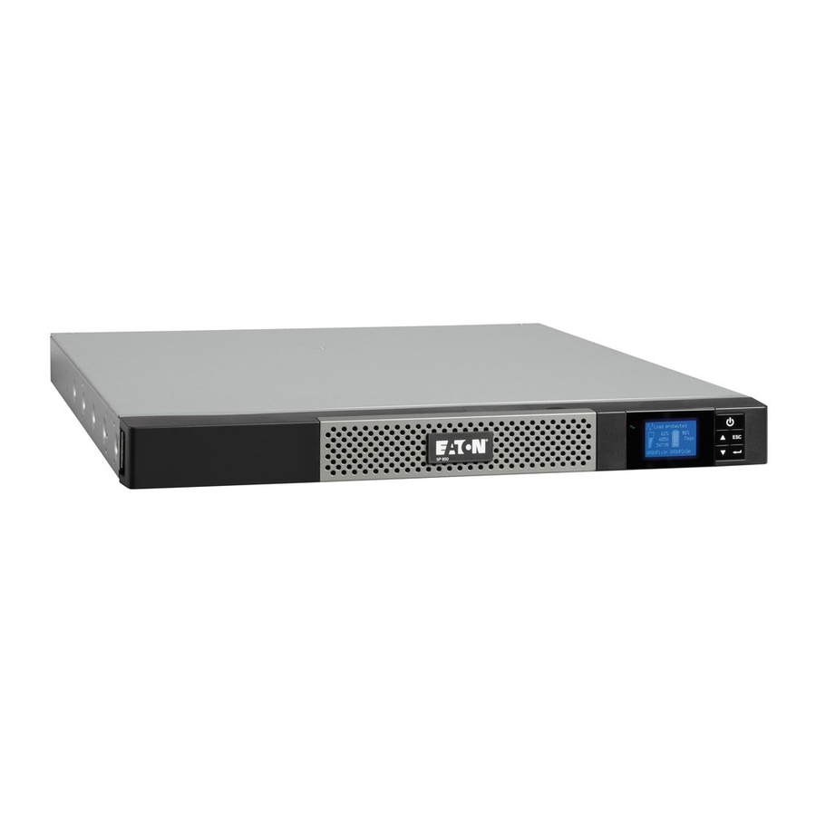
2. Presentation 2.4 Control panel The UPS has a five-button graphical LCD. It provides useful information about the UPS itself, load status, events, measurements and settings. Tower models Power On On battery Alarm Indicator Indicator Indicator (red) (green) (yellow) Normal mode 100% 100% 720W 10min 800VA Efficiency: ~98% Escape Down Enter On/Off button Rack models Alarm On/Off Indicator (red) button... -
Page 9: Lcd Description
2. Presentation 2.5 LCD description Operation status Normal mode 100% 100% Load/equipment status 720W 10min Battery status 800VA Efficiency: ~98% Efficiency and load group information As default, or after 5 minutes of inactivity, the LCD displays the screen saver. The backlight LCD automatically dims after 10 minutes of inactivity. Press any button to restore the screen. The following table describes the status information provided by the UPS Note. -
Page 10: Display Functions
2. Presentation 2.6 Display functions Press the Enter ( ) button to activate the menu options. Use the two middle buttons ( ) to scroll through the menu structure. Press the Enter ( ) button to select an option. Press the button to cancel or return to the previous menu. - Page 11 2. Presentation Description Available settings Default settings Load segments [Disable] [0s] [1 s] [2 s]…[65354 s] Group 1: Disable - Auto shutdown During a power outage, authorises Group 2: Disable delay to keep some equipment running while turning off other equipment. This feature allows to save battery power.
-
Page 12: Installation
3. Installation 3.1 Unpacking and contents check Tower models Rack models (1) 5P UPS (2) Quick start and safety instructions (3) User manual and IPSS (Intelligent Power Software Suite) CDROM (4) 2 connection cables for the protected equipment (5) RS232 communication cable (6) USB communication cable (7) Cable locking systems (1 x 4 outlets 650i R and 850i R models;... -
Page 13: Installation Of Tower Models
3. Installation 3.2 Installation of tower models 3.3 Wall installation of rack models (650i R / 850i R / 1150i R) Page 13 620-00082-02-i (en) -
Page 14: Installation Of Rack Models (650I R Only)
Follow steps 1 to 3 for rack mounting. 3.5 Installation of rack models (850i R / 1150i R / 1550i R) Follow steps 1 to 4 for module mounting on the rails. The rails and necessary hardware are supplied by EATON. Page 14 620-00082-02-i (en) -
Page 15: Communication Ports
(5) or (6) to the USB (1) or RS232 (2) communication port on the UPS. The UPS can now communicate with EATON power management software. Installation of the communication cards (optional) It is not necessary to shutdown the UPS before installing a communication card. -
Page 16: Operation
4.1 Start-up and Normal operation To start the UPS: 1. Verify that the UPS power cord is plugged in. 2. The UPS front panel display illuminates and shows EATON logo. 3. Verify that the UPS status screen shows 4. Press the button on the UPS front panel for at least 2 seconds. -
Page 17: Return Of Ac Input Power
4. Operation Low-battery warning • The indicator illuminates solid. • The audio alarm beeps every three seconds. The remaining battery power is low. Shut down all applications on the connected equipment because automatic UPS shutdown is imminent. End of battery backup time • LCD displays "End of backup time". -
Page 18: Maintenance
5. Maintenance 5.1 Troubleshooting Operation status Possible cause Action Batteries disconnected The UPS does not recognise If the condition persists, contact the internal batteries your service representative The batteries are disconnected Verify that all batteries are properly connected. If the condition persists, contact your service representative. -
Page 19: Battery-Module Replacement
Mounting the new battery module Carry out the above instructions in reverse order. • To ensure safety and high performance, use only batteries supplied by EATON. • Take care to firmly press together the two parts of the connector during remounting. -
Page 20: Mounting The New Battery Module
Mounting the new battery module Carry out the above instructions in reverse order. • To ensure safety and high performance, use only batteries supplied by EATON. • Take care to firmly press together the two parts of the connector during remounting. -
Page 21: Appendices
"AVR" Charger Inverter Battery Tower 5P 650i 5P 850i 5P 1150i 5P 1550i Rack 5P 650i R 5P 850i R 5P 1150i R 5P 1550i R Output Power 650 VA 850 VA 1150 VA 1550 VA 420 W 600 W... - Page 22 Page 22 620-00082-02-i (en)
Need help?
Do you have a question about the 5P 650i and is the answer not in the manual?
Questions and answers