
Related Manuals for Albany RAPID-ROLL 670


Summary of Contents for Albany RAPID-ROLL 670
- Page 1 ANUAL ® DOOR OWNER’S MANUAL RAPID-ROLL Model 670 & Model 570 975-A OLD NORCROSS ROAD LAWRENCEVILLE, GA 30045 (770) 338-5000 TEL (770) 338-5034 FAX (877) 925-2468 TOLL FREE...
- Page 2 Architectural Drawing of the 570 & 670 Rapid Roll Door Models Part N 6410T0006 Version 4/22/2010 umber...
-
Page 3: Table Of Contents
COUNTER-BALANCE SPRING INSTALLATION AND CABLE ROUTING .......... 12 STANDARD BOTTOM BEAM ........................ 12 BOTTOM BEAM EQUIPPED WITH SELF-REPAIRING DEVICE™ OPTION........16 BOTTOM BEAM EQUIPPED WITH RAPID RESET™ OPTION. (Model 670 Only) ......19 SPRING TENSIONING AND DOOR BALANCE ..................19 MAINTENANCE AND INSPECTION ......................22 DAILY INSPECTION.......................... -
Page 4: Statement Of Warranty
Albany Door Systems’ obligations under this warranty are limited to repairing or replacing the defective part including labor and Albany Door Systems shall not be responsible for any other losses or damages due to the operation of any door or parts covered by this warranty. Warranty parts will be shipped regular ground freight at the expense of Albany Door Systems. -
Page 5: Safety Practices
USE EXTREME CAUTION when it is necessary to service the control panel while it is energized. 10. If you have any questions, please contact your local Albany service provider for assistance. Otherwise contact Albany International at 1-877-925-2468 for information on your local distributor. -
Page 6: Packing List
Before beginning the installation, thoroughly inspect the crate to ensure all necessary components are there. The following list applies to a standard Model 570/670 door (no optional parts are indicated). Left Hand and Right Hand Side Frames with attached Covers (2 sets) -
Page 7: Rapid Roll Model 570/670 Installation
® RAPID ROLL MODEL 570/670 INSTALLATION FRAME AND GENERAL INSTALLATION Step 1 Unpack crate and inventory parts, comparing against the packing list in the front of this manual, to verify all parts are on site. Step 2 Using a tape measure; determine the actual door width by measuring the width gauge on the top roll assembly (Figure 1). - Page 8 Step 3 Verify that the opening is plumb and that the floor slab is level. If they are not, shimming and adjustments to the side frames must be made to accomplish this during door installation. Refer to approval drawings for this door to confirm drive side mounting (left or right-hand). Step 4 Remove side frames from crate (one at a time) and erect them into position against the wall at the pre-marked locations on the floor.
- Page 9 FIGURE 3 FIGURE 4 FIGURE 5 Part N 6410T0006 umber Version 4/23/2010...
- Page 10 Slide Motor onto Keyed Stub axle. Figure 5A Attach Limit sprocket to stub axle via bolt, bend tab up to secure. Attach “L” bracket mounted on motor to header assembly Figure 5B Part N 6410T0006 umber Version 4/23/2010...
- Page 11 Step 8 Cut the plastic straps that are tied around the top roll assembly and bottom beam. Allow the door curtain to drape down a maximum of two feet. Step 9 Install the top pulley brackets on both side frames using the four remaining 3/8”-16 bolts and the two center bolt holes in the side frame top clamping plates.
-
Page 12: Counter-Balance Spring Installation And Cable Routing
Correct Incorrect FIGURE 7 NOTE: the counter balance spring and cable installation section below is divided into two sections based on the bottom-beam type. Reference the section that is applicable to your installation. NOTE! : WITH 0-WRAPS THE CABLE DOES NOT HANGS STRAIGHT DOWN FROM THE CABLE DRUM. - Page 13 A. Starting on one side, install a counter balance spring into one side frame by hooking the spring tang in the side frame bottom plate bracket and standing it upright inside the side frame. B. Each spring has a tag indicating the door serial number, spring size, number of pre-wraps on cable drums, and spring pre-stretch distance.
- Page 14 NOTE: REFERENCE FIGURE 10 WHILE PERFORMING THE NEXT 4 STEPS. INSTALL CABLES AND SPRINGS ONE SIDE AT A TIME. FIGURE 10 F. Thread the cable through the intermediate pulley clamped to the side frame. Pull all of the cable slack through.
- Page 15 NOTE PRESTRETCH ON THE SPRING TAG IS A STARTING POINT AND MAY NEED TO BE EITHER INCREASED OR DECREASED TO ACHIEVE PROPER BALANCE. AFTER THIS IS ACHIEVED, USE A PERMANENT MARKER TO WRITE THE SPRING TAG INFORMATION ON THE INSIDE OF THE SIDE FRAME FOR FUTURE REFERENCE.
-
Page 16: Bottom Beam Equipped With Self-Repairing Device™ Option
BOTTOM BEAM EQUIPPED WITH SELF-REPAIRING DEVICE™ OPTION. A. Starting on one side, install a counter balance spring into one side frame by hooking the spring tang in the side frame bottom plate bracket and standing it upright inside the side frame. Each spring has a tag indicating the door serial number, spring size, number of pre-wraps on cable drums, and spring pre-stretch distance. - Page 17 NOTE: REFERENCE FIGURE 12 WHILE PERFORMING THE NEXT 7 STEPS. INSTALL CABLES AND SPRINGS ONE SIDE AT A TIME. FIGURE 12 F. Thread the cable through the intermediate pulley bracket clamped to the side frame. Pull all of the cable slack through. G.
- Page 18 down through the outside hole. Pull all slack out cable at this time. K. Tighten both set screws (#10-24) on cable clamp. L. Install the cable clamp back in the block and tighten the bolt. Ensure that clamp is able to swivel freely in the block.
-
Page 19: Bottom Beam Equipped With Rapid Reset™ Option. (Model 670 Only)
BOTTOM BEAM EQUIPPED WITH RAPID RESET™ OPTION. (Model 670 Only) For the model 670, the door size or wind load may cause the door design t exceed a practical limit to this technique. In this case, the Rapid Reset System (RRS) may be used. The mechanical installation is the same as the SRD. - Page 20 (Figure 15). Insert clear plastic tube onto nipple on pressure switch enclosure (Figure 16). Step 9 Close both side frame covers and secure them using the four locking pins provided (Figure 17 Model 670 doors)(Figure 18 for Model 570 doors). FIGURE 15...
- Page 21 FIGURE 16 FIGURE 17 FIGURE 18 Part N 6410T0006 umber Version 4/23/2010...
-
Page 22: Maintenance And Inspection
MAINTENANCE AND INSPECTION WARNING REMOVE ALL POWER AT THE FUSED DISCONNECT DURING ALL ELECTRICAL OR MECHANICAL SERVICING. DISCONNECT MUST BE PROPERLY LOCKED OUT DURING MAINTENANCE OR SERVICE OF EQUIPMENT. DAILY INSPECTION Run through a full door cycle (open/close) and ensure smooth operation. Verify that the door is not jammed or hanging up. -
Page 23: Rapid Roll Door 570/670 Maintenance Checklist
RAPID ROLL DOOR 570/670 MAINTENANCE CHECKLIST MAINTAINENCE ITEM/ PERIOD ACTION REFERENCE REVERSING / STOPPING FUNCTIONS Photoeyes / EM Reversing Edge / EM Contactless Safety Edge /6.2 Emergency Stop / EM TENSION SYSTEM Steel/Rope Cables /5.4.1 Cable Attachment Bolts /4.2 Cable Drum /5.4.3... -
Page 24: Inspections
INSPECTIONS WIRE ROPE INSPECTION All wire ropes will wear out eventually and gradually lose work capability throughout their service life. That’s why periodic inspections are critical. Applicable industry standards such as ASME B30.2 for overhead and gantry cranes or federal regulations such as OSHA refer to specific inspection criteria for varied applications. - Page 25 A wire rope that has been subjected to repeated bending over sheaves under normal loads. This results in fatigue breaks in individual wires – these breaks are square and usually in the crown of the strands. An example of fatigue failure of a wire rope subjected to heavy loads over small sheaves.
-
Page 26: Pulley Inspection
Here’s a wire rope that has jumped a sheave. The rope “curled” as it went over the edge of the sheave. When you study the wires, you’ll see two types of breaks here: tensile “cup and cone” breaks and shear breaks that appear to have been cut on an angle. -
Page 27: Brake Adjustment
BRAKE ADJUSTMENT The motor brake is located inside the fan cover compartment of the motor. It can be accessed by removing the fan cover. Refer to Figure 28 while following this procedure. WARNING MAKE SURE THE DOOR IS POWERED DOWN AND LOCKD OUT BEFORE REMOVING THE FAN COVER. -
Page 28: Option Installation And Operation
OPTION INSTALLATION AND OPERATION CHAIN DRIVE INSTALLATION This option adds a bracket and chain drive sprockets to remote the standard drive unit out in front of the door top roll. It is used in applications with limited side room clearance. This option is not available with an All... - Page 29 1. Mount the chain drive bracket to the side frame using the (4) 3/8-16 nuts and existing studs on axle bearing bracket. 2. Attach the chain sprocket, 28mm diameter bore, to the stub axle and tighten set screw. 3. Mount the drive unit to the chain drive bracket using the (4) M16 x 30mm hex head bolts. Ensure chain tensioner bracket (“L”...
-
Page 30: Contactless Safety Edge™ (C.s.e.)
CONTACTLESS SAFETY EDGE™ (C.S.E.) MECHANICAL INSTALLATION This patented reversing feature utilizes through beam photocells that are mounted on retractable stainless steel tubes located on each end of the bottom beam. The photocells travel 6” below the leading edge during door travel and reverse the door immediately when an object is detected before edge strikes object. -
Page 31: Electrical Installation
PACKING LIST Cable chain, (2 pieces, length dependent upon height of door) LH & RH C.S.E. guide bar assemblies NOTE REFERENCE FIGURE 30 WHILE PERFORMING THIS PROCEDURE WARNING ENSURE THE DOOR COUNTER BALANCE SYSTEM HAS BEEN INSTALLED AND PROPERLY TENSIONED PRIOR TO PERFORMING THIS PROCEDURE. 1. -
Page 32: Adjustments
ADJUSTMENTS Adjustments to the photo amplifier box will be required at installation of the C.S.E. and may also require periodic adjustments. (See Figure 31) 1. Activate door and stop it at a central location (i.e. 5 feet off the ground) using the EMERGENCY STOP button. - Page 33 FRONT COVER INSTALLATION NOTE REFERENCE FIGURE 32 WHILE PERFORMING THIS PROCEDURE FIGURE 32 1. Attach front cover mounting brackets to both axle bearing brackets utilizing pre-tapped holes in bearing brackets. 2. Lift the cover into place in front of both mounting brackets. 3.
-
Page 34: Full Roll Cover & Motor Cover Installation
FULL ROLL COVER & MOTOR COVER INSTALLATION NOTE REFERENCE FIGURE 33 WHILE PERFORMING THIS PROCEDURE FIGURE 33 1. Attach full roll cover mounting brackets to the axle bearing brackets. 2. Lift the cover into place in front of the mounting brackets. 3. -
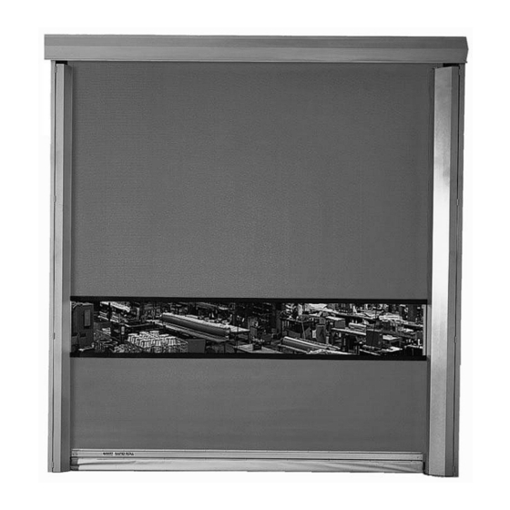
Page 35: Full Vision Panel™Replacement
The Full Vision Panel™ consists of a 24” clear PVC panel the runs the entire width of the door. It is attached to the fabric approximately four to five feet off the floor. This option is not available on a 670 with a Self-Repairing Device™... - Page 36 FIGURE 35 Pull the bottom hinge pin out of the clips (Figure 35). In order to prevent damage to these parts, support the bottom door panel and bottom beam during this step. This will prevent them from dropping to the floor.
- Page 37 Before threading the hinge pin, ensure the Full Vision Panel™ is centered with respect to the door panel. Lubricate the clips and/or hinge pin with a small amount of light oil (or similar lubricant). This will help facilitate the threading procedure. Thread the hinge pin between the loops in the clips.
- Page 38 Figure 37 Part N 6410T0006 umber Version 4/23/2010...
- Page 39 Figure 38 NOTE ENSURE THE HINGE PIN DOES NOT BECOME TWISTED AS THE SLACK IS PULLED OUT. DEPENDING ON THE DOOR PANEL WIDTH, SEVERAL LOOPS MAY BE REQUIRED TO HELP FACILITATE THREADING OF THE PIN. Part N 6410T0006 umber Version 4/23/2010...
- Page 40 When the hinge pin is completely threaded through the entire length of the clips, loop it back through the clips for six to eight inches, and then back to the end again. Cut off excess on each end of the pin (Figure 37).
-
Page 41: Manual Disengagement
MANUAL DISENGAGEMENT The manual disengagement lever assembly allows the drive unit brake to be released remotely. Two lever assemblies may be installed on the motor. The flexible cables of the assemblies allow them to be mounted at various positions on the same side of the wall as the drive unit or can be mounted remotely on the opposite side of a wall. - Page 42 Figure 39A Part N 6410T0006 umber Version 4/23/2010...
-
Page 43: Manual Hoist Installation
MANUAL HOIST INSTALLATION This option eliminates the drive unit and allows the door to be operated manually via a manual hoist. NOTE REFERENCE FIGURE 40 WHILE PERFORMING THIS PROCEDURE Mount manual hoist housing on wall a few inches below stub axle on drive side of door. -
Page 44: Manual Hoist With Disconnect Installation
MANUAL HOIST WITH DISCONNECT INSTALLATION This option allows disengagement of the gearbox while allowing the door to be operated via a manual hoist. The manual hoist itself has a disconnect feature (mechanical and electrical) that allows it to spin freely when operating the door with a drive unit. NOTE REFERENCE FIGURE 41 WHILE... - Page 45 ride securely on both sprockets by removing links as necessary. Secure the chain by joining the end links together. Thread the hand chain through the chain guide holes and over the pocket wheel. Secure the chain by joining the end links together. Mount disengagement lever approximately five feet above the floor.
-
Page 46: Windbar Installation
WINDBAR INSTALLATION GENERAL A windbar is a hollow aluminum tube that runs the entire width of the door to provide additional wind resistance to the door fabric. It runs up and down in vertically mounted C-channels attached to both side frames. - Page 47 Ensure the side frame covers are closed. Close the door fabric completely. Attach the two windbar strap attachment blocks to the top of each windbar strap bracket using the supplied #10-32 x ¾” cap screws (view A-A). Do not fully tighten the screws at this time. Measure from the top edge of the bottom beam assembly to the top edge of the windbar channel on each side frame cover and mark the centerline of this dimension on the inside of each windbar channel.
- Page 48 on the brake release lever (All star™ with pulse encoder drive unit). Manually move the door to the fully open position. Ensure the windbar is lifted by the straps and remains inside the windbar channel. Check the windbar level again and adjust the straps again if necessary. Cut the excess strap at least 3 to 6 inches from the clamps.
-
Page 49: Strapless Windbar Installation
STRAPLESS WINDBAR INSTALLATION NOTE REFERENCE FIGURES 44, 45, 46 WHILE PERFORMING THIS PROCEDURE NOT AVIALIBLE WITH SRD OR RRS OPTIONS Ensure the side frame covers are closed. Close the door fabric completely. Insert the windbar from the top of the windbar channel and slowly lower it onto the windbar stops located inside the C-channel (view A-A). - Page 50 FIGURE 45 Figure 46 Part N 6410T0006 umber Version 4/23/2010...
-
Page 51: Air Circulation System
AIR CIRCULATION SYSTEM MECHANICAL INSTALLATION NOTE: REFERENCE FIGURE 47 WHILE PERFORMING THIS PROCEDURE FIGURE 52 FIGURE 47 Locate the pre-drilled mounting holes on the top roll assembly. Lift ACS unit into place in front the door top troll assembly. Attach ACS unit to door using supplied ¼ – 20 bolts (4 per ACS unit). Part N 6410T0006 umber... -
Page 52: Electrical Installation
ELECTRICAL INSTALLATION CAUTION ELECTRICAL SHOCK HAZARD. DISCONNECT POWER SOURCE WHENEVER SERVICING UNIT. WARNING TO REDUCE THE RISK OF FIRE OR ELECTRICAL SHOCK, DO NOT USE THIS FAN WITH ANY SOLID STATE SPEED CONTROL DEVICE. Ensure the correct voltage, as marked on the unit, is used. Provide electrical disconnect and wire according to ACS wiring diagram (Figure 48). -
Page 53: Air Flow Adjustments
Connect the proper size cables (supplied by other) to the pigtail leads in the junction boxes. Run wires for switch controls back to the main control panel. AIR FLOW ADJUSTMENTS With the ACS operating and the door in its full open position, check to see that nothing is obstructing the airflow at the discharge nozzle. - Page 54 MAINTENANCE AND CLEANING WARNING THE MOTOR HAS INTERNAL SELF-RESETTING OVERLOAD PROTECTION. ALWAYS DISCONNECT THE POWER SOURCE BEFORE SERVICING. To keep your ACS operating at peak efficiency, semi-annual cleaning of the blower wheels and housings is recommended. Remove dust and dirt build-up from the blower wheels and housings. The motor is totally enclosed and permanently lubricated.
-
Page 55: Rapid Roll Model 570/670 Installation Checklist
Door limits properly set. Gearbox breather plug installed. All actuators tested and function properly. Door has been cycled at least 10 times to verify proper operation. Notes:______________________________________________________________________________________ ___________________________________________________________________________________________ ____________________________________________________ FAX COMPLETED FORM TO ALBANY INTERNATIONAL SERVICE DEPARTMENT AT (770) 338-5034. - Page 56 NOTES 670 Owner’s Manual DOCUMENT TITLE 6410T0005 DOCUMENT NUMBER VERSION DATE 4/23/2010 DOOR MODEL(S) 570/670 ELECTRONIC FILE 670-570Owners Manual.DOC ASSEMBLY Owners Manual REPLACES MANAGER ORIGINATOR Rick Walton / Andrew Wojcik APPROVAL/DATE Part N 6410T0006 umber Version 4/23/2010...
Need help?
Do you have a question about the RAPID-ROLL 670 and is the answer not in the manual?
Questions and answers