Table of Contents
Advertisement
Advertisement
Table of Contents

Related Manuals for Palstar AT2K


Summary of Contents for Palstar AT2K
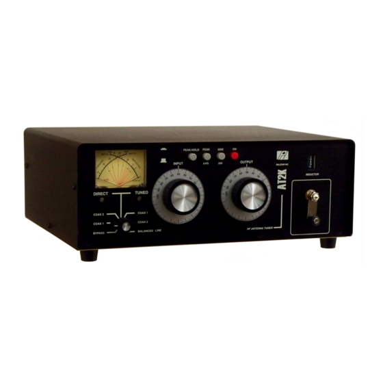
- Page 1 AT2K 2000 Watt Antenna Tuner Palstar Incorporated 9676 N. Looney Rd., Piqua, OH 45356 USA Owner’s Manual Customer Service and Sales Telephone: 1-800-773-7931 Fax: 1-937-773-8003 Email: info@palstar.com © Copyright 2010 Palstar Inc. Printed in the U.S.A. Rev. 2.0 24 MAY 2010...
-
Page 2: Important Safeguards
5. Cleaning—Unplug this appliance from the is equipped with a 3-wire line cord receptacle. wish to pay for the service. Package your unit properly. Palstar, Inc. is wall outlet before cleaning. Do not use liquid It is intended for use with a 3-wire properly not responsible for merchandise damaged in shipment. - Page 3 An improper adjust- mation. ment may result in damage and will often e. Use jumper wire not smaller than No.6 require extensive work by a qualified AWG copper or equivalent, when a separate antenna grounding electrode is used. 1-800-773-7931 WWW.PALSTAR.COM 1-800-773-7931 WWW.PALSTAR.COM...
-
Page 4: Table Of Contents
Table of Contents AT2K Internal Photo 17 Thank you for purchasing a Please carefully read the Palstar AT2K Antenna Tuner. Owner’s Manual in order to take Ceramic This antenna tuner has been advantage of the many interest- Variable Roller designed and manufactured to... -
Page 5: General Description
Meter Board Adjustments AT2K General Description Note: These adjustments control the calibration and accuracy of the AT2K metering. Do not adjust unless you are sure the metering is inaccurate, and you have accurate test equipment to check against. Reverse Reverse... -
Page 6: Installation
Power Range Switch 2 position 300 W /3000 W DIRECT/TUNED mode switch. Rear Panel Connectors Select a location for the AT2K Any antenna that does not re- that allows the connectors to be quire the use of an antenna RF INPUT... - Page 7 Operating Your AT2K cont’d Installation continued 10. When you have tuned your antenna to the best SWR, re- COAX 2 coaxial connector for cord the settings of the INPUT, ANTENNA and INDUC- output to Antenna Two. TANCE controls on the chart above for future reference.
-
Page 8: Front Panel Description
Front Panel Description Operating Your AT2K cont’d Do not exceed 1500 watts average (single tone). 5. Set RANGE switch to 300 W (button out). 6. Set the DIRECT/TUNED mode switch to the TUNED po- sition matching your antenna connection. To tune your an- tenna, the switch selection must be set to: COAX 1 TUNED, COAX 2 TUNED or BALANCED LINE. -
Page 9: Operating Your At2K
The end stop readings on the turns counter are Zero and 279. Zero is 1. To avoid possible damage to the AT2K set INPUT, OUT- maximum inductance, and 279 is minimum inductance. PUT, INDUCTOR, and POWER RANGE switches as out- 7. - Page 10 AT2K Schematic AT2K Schematic Optional External 25uH 1-800-773-7931 WWW.PALSTAR.COM 1-800-773-7931 WWW.PALSTAR.COM...
Need help?
Do you have a question about the AT2K and is the answer not in the manual?
Questions and answers