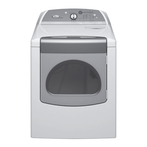
Whirlpool Cabrio WED6200S User Manual
Gas & electric dryers
Hide thumbs
Also See for Cabrio WED6200S:
- Dimensions and installation (1 page) ,
- Use & care manual (32 pages) ,
- Dimensions and installation information (1 page)

Related Manuals for Whirlpool Cabrio WED6200S


Summary of Contents for Whirlpool Cabrio WED6200S
- Page 1 L-82 CONSUMER CARE TECHNICAL EDUCATION GROUP PRESENTS GAS & ELECTRIC DRYERS MODELS: ELECTRIC - WED6200S & WED6400S GAS - WGD6200S & WGD6400S JOB AID Part No. 8178584...
- Page 2 • Successfully perform necessary repairs. • Successfully return the dryer to its proper operational status. WHIRLPOOL CORPORATION assumes no responsibility for any repairs made on our products by anyone other than authorized In-Home Service Professionals. Copyright © 2006, Whirlpool Corporation, Benton Harbor, MI 49022...
-
Page 3: Table Of Contents
TABLE OF CONTENTS Page GENERAL ............. . 1-1 Dryer Safety . - Page 4 Page DIAGNOSTICS & TROUBLESHOOTING ........6-1 Electric Dryers .
-
Page 5: General
GENERAL DRYER SAFETY Your safety and the safety of others are very important. We have provided many important safety messages in this manual and on your appliance. Always read and obey all safety messages. This is the safety alert symbol. This symbol alerts you to potential hazards that can kill or hurt you and others. -
Page 6: Model & Serial Number Designations
MODEL & SERIAL NUMBER DESIGNATIONS MODEL NUMBER MODEL NUMBER 00 S W BRAND W = Whirlpool E = Estate R = Roper I = Inglis ACCESS / FUEL T = Top Load G = Gas F = Front Load H = Horizontal... -
Page 7: Model & Serial Number Label & Tech Sheet Locations
MODEL & SERIAL NUMBER LABEL & TECH SHEET LOCATIONS The Model/Serial Number Label and Tech Sheet locations are shown below. Tech Sheet Location (Access Under Console) Model/Serial Number Location... -
Page 8: Specifications
SPECIFICATIONS MODEL NUMBERS ELECTRIC WED6200SW WED6400SW, G, B WGD6200SW WGD6400SW, G, B PRIMARY FEATURES CAPACITY (CU. FT.) CAPACITY Super Capacity Plus Super Capacity Plus # OF CYCLES HEAVY DUTY NORMAL CASUAL DELICATE TIMED DRY QUICK DRY TOUCH UP DAMP DRY SIGNAL TEMPERATURE SETTINGS HIGH 155 ±5°F (68.3°C) -
Page 9: Installation Information
INSTALLATION INFORMATION INSTALLATION INSTRUCTIONS Parts supplied: TOOLS AND PARTS Remove parts package from dryer drum. Gather the required tools and parts before Check that all parts were included. starting installation. Read and follow the in- structions provided with any tools listed here. Electric Models •... -
Page 10: Location Requirements
LOCATION REQUIREMENTS INSTALLATION CLEARANCES The location must be large enough to allow WARNING the dryer door to open fully. Dryer Dimensions 43 ½" (110.5 cm) Explosion Hazard Keep flammable materials and vapors, such as gasoline, away from dryer. (56. 5cm) *29 ¼"... - Page 11 • Additional spacing is required if you ex- Mobile Home - Additional Installation Re- haust out the rear of the dryer to either the quirements right or left side. This dryer is suitable for mobile home instal- lations. The installation must conform to the 3"* (7.6 cm) 14"...
- Page 12 ELECTRICAL REQUIREMENTS - • This dryer is manufactured ready to install with a 3-wire electrical supply connection. U.S.A. ONLY The neutral ground wire is permanently Electric Models Only connected to the neutral conductor (white wire) within the dryer. If the dryer is installed It is your responsibility with a 4-wire electrical supply connection, •...
-
Page 13: Grounding Instructions
If your outlet looks like this: GROUNDING INSTRUCTIONS • For a grounded, cord-connected dryer: This dryer must be grounded. In the event of malfunction or breakdown, ground- 4-wire receptacle (14-30R) ing will reduce the risk of electric shock by providing a path of least resistance for Then choose a 4-wire power supply cord with ring or spade terminals and UL listed strain electric current. -
Page 14: Electrical Requirements
ELECTRICAL REQUIREMENTS - • Do not use an extension cord. CANADA ONLY • If you are using a replacement power sup- ply cord, it is recommended that you use Electric Models Only Power Supply Cord Replacement Part WARNING Number 3394208. For further information, please reference the service numbers lo- cated in the “Assistance or Service”... - Page 15 ELECTRICAL CONNECTION - DIRECT WIRE U.S.A. ONLY WARNING POWER SUPPLY CORD WARNING Fire Hazard Use 10 gauge solid copper wire. Use a UL listed strain relief. Fire Hazard Disconnect power before making Use a new UL listed 30 amp power electrical connections.
- Page 16 • Put power supply cord through the strain • Put direct wire cable through the strain re- relief. Be sure that the wire insulation on lief. The strain relief should have a tight fit the power supply cord is inside the strain with the dryer cabinet and be in a horizontal relief.
- Page 17 4-wire connection: Power supply cord Connect ground wire (green or bare) of power supply cord to external ground IMPORTANT: A 4-wire connection is required conductor screw. Tighten screw. for mobile homes and where local codes do not permit the use of 3-wire connections. A.
- Page 18 4-wire connection: Direct Wire Remove center silver-colored terminal block screw. IMPORTANT: A 4-wire connection is required for mobile homes and where local codes do Remove neutral ground wire from exter- not permit the use of 3-wire connections. nal ground conductor screw. Connect neutral ground wire and place the hooked Direct wire cable must have 5 ft (1.52 m) of end (hook facing right) of the neutral wire...
- Page 19 Connect ground wire (green or bare) of 3-wire connection: Power supply cord direct wire cable to external ground con- Use where local codes permit connecting ductor screw. Tighten screw. cabinet-ground conductor to neutral wire. A. 3-wire receptacle (NEMA type 10-30R) B.
- Page 20 Tighten strain relief screws. Loosen or remove center silver-colored terminal block screw. Insert tab of terminal block cover into slot of dryer rear panel. Secure cover with Place the hooked end of the neutral wire hold-down screw. (white or center wire) of direct wire cable under the center screw of terminal block You have completed your electrical con- (hook facing right).
- Page 21 Optional 3-wire connection Connect the other wires to outer terminal block screws. Tighten screws. Use for direct wire or power supply cord where local codes do not permit connect- ing cabinet-ground conductor to neutral wire. Remove center silver-colored terminal block screw. Remove neutral ground wire from exter- Tighten strain relief screws.
-
Page 22: Gas Models Only
ELECTRICAL REQUIREMENTS GROUNDING INSTRUCTIONS Gas Models Only • For a grounded, cord-connected dryer: WARNING This dryer must be grounded. In the event of malfunction or breakdown, grounding will reduce the risk of elec- tric shock by providing a path of least resistance for electric current. -
Page 23: Gas Supply Requirements
GAS SUPPLY REQUIREMENTS GAS SUPPLY LINE • 1/2˝ IPS pipe is recommended. WARNING • 3/8˝ approved tubing is acceptable for lengths under 20 ft (6.1 m) if local codes and gas supplier permit. • Must include 1/8˝ NPT minimum plugged tapping accessible for test gauge connec- tion, immediately upstream of the gas con- nection to the dryer (see illustration). - Page 24 GAS SUPPLY CONNECTION BURNER INPUT REQUIREMENTS REQUIREMENTS Elevations above 2,000 ft (610 m): • Use an elbow and a 3/8˝ flare x 3/8˝ NPT • When installed above 2,000 ft (610 m) a adapter fitting between the flexible gas con- 4% reduction of the burner B.T.U.
-
Page 25: Venting Requirements
™ result in death or fire. from your dealer or by calling Whirlpool Parts and Accessories. For more information, see WARNING: To reduce the risk of fire, this dry- the “Assistance or Service” section of the er MUST BE EXHAUSTED OUTDOORS. - Page 26 Elbows The angled hood style (shown here) is ac- ceptable. 45° elbows provide better airflow than 90° el- bows. 4" (10.2 cm) 2½" (6.4 cm) • An exhaust hood should cap the vent to keep rodents and insects from entering the Good Better home.
-
Page 27: Plan Vent System
PLAN VENT SYSTEM NOTE: The following kits for close clearance alternate installations are available for pur- Recommended exhaust installations chase. Please see the “Assistance or Service” Typical installations vent the dryer from the section of the “Use & Care Guide” to order: rear of the dryer. - Page 28 Determine vent path The Vent system chart provides venting re- quirements that will help to achieve the best • Select the route that will provide the drying performance. straightest and most direct path outdoors. Vent system chart • Plan the installation to use the fewest num- ber of elbows and turns.
-
Page 29: Install Vent System
INSTALL VENT SYSTEM Screw the legs into the leg holes by hand. Use a wrench to finish turning the legs Install exhaust hood. Use caulking com- until the diamond marking is no longer pound to seal exterior wall opening visible. around exhaust hood. -
Page 30: Level Dryer
A combination of pipe fittings must be used Move dryer into its final location. Do not to connect the dryer to the existing gas line. crush or kink vent. Shown is a recommended connection. The (On gas models) Make sure that there connection may be different, according to the are no kinks in the flexible gas line. -
Page 31: Reverse Door Swing
REVERSE DOOR SWING Remove the 4 plastic plug strips located outside the dryer door opening. You can change your door swing from a right- side opening to a left-side opening, if de- sired. Place a towel or soft cloth on top of the dryer or work space to protect the sur- face. - Page 32 Reinstall the door Install the 2 hinges to the front panel of the dryer using 4 screws. Use the non- Remove the 4 screws and 2 hinges from slotted side to attach the hinge to the the dryer door. front panel. Replace the 4 screws in the same holes.
-
Page 33: Complete Installation
COMPLETE INSTALLATION 11. Electric Models Only: When the dryer has been running for 5 minutes, open the Check that all parts are now installed. If dryer door and feel for heat. If you feel there is an extra part, go back through the heat, cancel cycle and close the door. - Page 34 — NOTES — 2-26...
-
Page 35: Product Operation
PRODUCT OPERATION DRYER USE WARNING WARNING Explosion Hazard Fire Hazard Keep flammable materials and vapors, No washer can completely remove oil. such as gasoline, away from dryer. Do not dry anything that has ever had Do not dry anything that has ever had any type of oil on it (including cooking anything flammable on it (even after oils). -
Page 36: Starting The Dryer
STARTING THE DRYER To make changes during an Automatic Cycle: This manual covers several different models. • Press PAUSE/CANCEL. Your dryer may not have all of the cycles and features described. • Adjust Dryness. Follow these basic steps to start your dryer. NOTE: Dryness selections can be made Please refer to specific sections of this manual only while using Automatic Cycles. -
Page 37: Drying And Cycle Tips
NOTE: During a Timed Cycle, you can change Cool Down tumbles the load without heat the settings for Time, Temp, the WRINKLE during the last few minutes of all cycles. Cool SHIELD setting and the End of Cycle Signal. Down makes the loads easier to handle and ™... -
Page 38: Status Lights
STATUS LIGHTS INDICATOR LIGHTS Other indicator lights show Cycle, Options, Follow the progress of your dryer with the dry- Modifiers and Cycle Signal settings selected. ing Status indicator lights. The display shows the estimated or actual time remaining. CYCLES SENSING Select the drying cycle that matches the type •... -
Page 39: Timed Cycles
Automatic Preset Cycle Settings Timed Preset Cycle Settings Timed Cycles Default Default Time Automatic Cycles Temperature Load Type Temperature (Minutes) Load Type TIMED DRY High HEAVY DUTY High Heavyweight, bulky items, Heavyweight mixed loads, cottons, work clothes jeans QUICK DRY Medium NORMAL Medium... - Page 40 AIR ONLY When the dryer is not running, the drum light will turn on when DRUM LIGHT is pressed or Use the Air Only Modifier for items that require the dryer door is opened, and it will remain on drying without heat such as rubber, plastic until the dryer door has been open for 5 min- and heat-sensitive fabrics.
-
Page 41: End Of Cycle Signal
NOTE: The Damp Dry Signal is available only CHANGING CYCLES AFTER with the Automatic Cycles. PRESSING START 1. Press PAUSE/CANCEL twice. END OF CYCLE SIGNAL 2. Select the desired cycle and options. END OF CYCLE SIGNAL 3. Press START. The dryer starts at the begin- The End of Cycle Signal produces an au- ning of the new cycle. - Page 42 NOTE: The rack must be removed for normal 4. Close the door. tumbling. Do not use the automatic cycle with 5. Press the POWER button. the drying rack. 6. Select a timed drying cycle and temperature To use the drying rack: (see the following chart).
-
Page 43: Dryer Care
DRYER CARE CLEANING THE DRYER LOCATION 2. Push the lint screen firmly back into place. Keep dryer area clear and free from items that would obstruct the flow of combustion and AS NEEDED CLEANING ventilation air. 1. Roll lint off screen with your fingers. WARNING 2. - Page 44 VACATION AND MOVING CARE 1. Disconnect power. 2. Disconnect wiring. VACATION CARE 3. Make sure leveling legs are secure in dryer Operate your dryer only when you are at home. base. If you will be on vacation or not using your dryer for an extended period of time, you should: 4.
-
Page 45: Troubleshooting
TROUBLESHOOTING DRYER OPERATION Dryer will not run Unusual sounds • Has a household fuse blown, or has a • Has the dryer had a period of non-use? circuit breaker tripped? If the dryer hasn’t been used for a while, There may be 2 household fuses or circuit there may be a thumping sound during the breakers for the dryer. - Page 46 DRYER RESULTS WARNING Clothes are not drying satisfactorily, drying times are too long, or load is too hot • Is the lint screen clogged with lint? Lint screen should be cleaned before each load. Explosion Hazard WARNING Keep flammable materials and vapors, such as gasoline, away from dryer.
- Page 47 • Is the automatic cycle ending early? Loads are wrinkled The load may not be contacting the sen- • Was the load removed from dryer at the sor strips. Level the dryer. Change the end of the cycle? dryness level setting on Automatic Cycles. Increasing or decreasing the dryness level •...
- Page 48 — NOTES — 3-14...
-
Page 49: Component Access
COMPONENT ACCESS ™ This section instructs you on how to service each component inside the Cabrio Gas & Electric Dryers. The components and their locations are shown below. COMPONENT LOCATIONS Electric Dryer Components Machine Control Electronics User Interface Assembly Thermal Cutoff Drum Light Assembly Inlet Thermistor/ High Limit Thermostat... -
Page 50: Removing The Encoder, User Interface Board, And Machine Control
REMOVING THE ENCODER, USER INTERFACE BOARD, AND MACHINE CONTROL WARNING Disconnect the user interface (UI) board ca- ble connector from machine control board connector P5. Machine Control Connector P5 Electrical Shock Hazard Disconnect power before servicing. Replace all parts and panels before operating. - Page 51 To remove the encoder, lift the lock- User Interface Board ing tab, and turn the encoder to the left (counterclockwise) as far as it will go. Lift the encoder straight up so that the shaft slides out of the rubber console seal, and remove it from the console.
- Page 52 c) Push the clip on the back, and slide Housing Bracket the machine control housing to the left and off the mounting bracket and re- move the assembly. Slide Machine Control...
-
Page 53: Removing The Cabinet Front And Door Switch
REMOVING THE CABINET FRONT AND DOOR SWITCH WARNING Electrical Shock Hazard Top Locks Disconnect power before servicing. Replace all parts and panels before b) Disconnect the door switch connector operating. from the harness connector. Failure to do so can result in death or c) Remove the two 5/16˝... - Page 54 To remove the door switch: c) Press in on the locking tabs, push the switch out of the cabinet cutout, and a) Remove the cabinet front (see step 5). remove it from the cabinet front. b) Unhook the door switch wires from the cabinet front clips.
-
Page 55: Removing The Belt, Drum, & Rollers
REMOVING THE BELT, DRUM, & ROLLERS WARNING Loosen the two top and remove the two bottom 5/16˝ hex-head screws from the front bulkhead. Lift and unhook the two top bulkhead key- hole slots from the screws, and remove the bulkhead from the dryer. Electrical Shock Hazard Disconnect power before servicing. - Page 56 b) Pull the drum out the front of the cabi- To remove a front or rear bulkhead net and remove it. roller, push the triangular clip off the grooved slot in the roller shaft, and pull Hole With Clip the roller off the shaft. Toward Rear Of Unit Triangular Clip Front Rollers...
-
Page 57: Removing The Drive Motor And Belt Switch
REMOVING THE DRIVE MOTOR AND BELT SWITCH WARNING 13/16˝ Blower Wheel Electrical Shock Hazard Loosen Disconnect power before servicing. Flatted Replace all parts and panels before Drive Shaft operating. Failure to do so can result in death or electrical shock. Unplug dryer or disconnect power. - Page 58 c) Remove the front and rear clamps from the drive motor and its mounting bracket. To remove a clamp, press down on one Front Clamp Rear Clamp end, and unhook it from the bracket tab. Longer Leg REASSEMBLY NOTE 2: When you reinstall the drive motor, make sure that the rounded locator tab is in the bracket slot, as shown below.
-
Page 59: Removing The Thermal Fuse & Exhaust Thermistor
REMOVING THE THERMAL FUSE & EXHAUST THERMISTOR WARNING Electrical Shock Hazard Disconnect power before servicing. Replace all parts and panels before operating. Failure to do so can result in death or electrical shock. Unplug dryer or disconnect power. Turn off gas supply to dryer. Remove the rear panel (see page 4-17 for the procedure). -
Page 60: Removing The High-Limit Thermostat And Thermal Cutoff (Tco)
REMOVING THE HIGH-LIMIT THERMOSTAT AND THERMAL CUTOFF (TCO) (GAS MODELS ONLY) WARNING Screw RD-WH High-Limit Thermostat Electrical Shock Hazard Disconnect power before servicing. Thermal Replace all parts and panels before Screws Cutoff (TCO) operating. Failure to do so can result in death or electrical shock. -
Page 61: Removing The Thermal Cutoff (Tco), Heater, And Inlet
REMOVING THE THERMAL CUTOFF (TCO), HEATER, AND INLET THERMISTOR / HIGH-LIMIT THERMOSTAT (ELECTRIC MODELS ONLY) WARNING Thermal Cutoff (TCO) Electrical Shock Hazard Screw Disconnect power before servicing. Replace all parts and panels before operating. Failure to do so can result in death or electrical shock. - Page 62 d) Remove the two hex-head screws from e) Using a flat-blade screwdriver, pry the the heater assembly and remove the inlet thermistor terminal off the heater assembly. terminal, and remove the thermistor from the assembly. Heater Assembly Screws Heater Assembly Heater Assembly Terminal Pry Tab Off With Screwdriver Lift &...
-
Page 63: Removing The Flame Sensor And Gas Burner Assembly
REMOVING THE FLAME SENSOR AND GAS BURNER ASSEMBLY (GAS MODELS ONLY) To remove the flame sensor: WARNING a) Remove the two wires from the sen- sor terminals. b) Remove the hex-head screw, then un- hook the tab, and remove the flame sensor from the burner venturi. - Page 64 To remove the coils from the burner Flame Sensor assembly: Connector a) Remove the burner assembly (see step b) Disconnect the 2-wire and 3-wire con- nectors from the coil pins. c) Remove the two screws from the brack- et, and lift the two coils off their cores. Burner Harness Connector Support Bracket Screw...
-
Page 65: Removing The Moisture Sensor And Metal Oxide Varistors (Movs)
REMOVING THE MOISTURE SENSOR AND METAL OXIDE VARISTORS (MOVS) WARNING To remove the metal oxide varistors (MOVs): a) Raise the lint screen lid and remove the two screws from the top of the lint screen air duct. Electrical Shock Hazard Disconnect power before servicing. - Page 66 Remove the four screws from the air Disconnect the two wires from the termi- duct and pull the duct toward you just far nals of the moisture sensor strips. enough to access the moisture sensor Unlock and disconnect the moisture sen- wiring harness.
-
Page 67: Removing The Drum Light Assembly
REMOVING THE DRUM LIGHT ASSEMBLY WARNING Drum Light Holder Screw Electrical Shock Hazard Drum Bulb Disconnect power before servicing. Replace all parts and panels before operating. Failure to do so can result in death or electrical shock. Disconnect the wire connectors from the light socket terminals. - Page 68 — NOTES — 4-20...
-
Page 69: Component Testing
COMPONENT TESTING Before testing any of the components, perform • Check all connections before replacing the following checks: components, looking for broken or loose wires, failed terminals, or wires not pressed • The most common cause for control failure into connectors far enough. is corrosion on connectors. -
Page 70: Thermal Fuse & Exhaust Thermistor
WARNING Electrical Shock Hazard Disconnect power before servicing. Replace all parts and panels before operating. Failure to do so can result in death or electrical shock. THERMAL FUSE & EXHAUST HIGH-LIMIT THERMOSTAT & THERMISTOR THERMAL CUTOFF (TCO) (GAS MODELS ONLY) Thermal Fuse High-Limit Thermostat... -
Page 71: Flame Sensor
WARNING Electrical Shock Hazard Disconnect power before servicing. Replace all parts and panels before operating. Failure to do so can result in death or electrical shock. FLAME SENSOR GAS BURNER COILS Burner Coils Refer to page 4-15 for the procedure for ac- cessing the flame sensor. -
Page 72: Burner Ignitor
WARNING Electrical Shock Hazard Disconnect power before servicing. Replace all parts and panels before operating. Failure to do so can result in death or electrical shock. ELECTRIC HEATER BURNER IGNITOR (DUAL ELEMENT) Burner Ignitor 2-Wire Connector Dual Element Heater Refer to page 4-13 for the procedure for ac- Refer to page 4-15 for the procedure for ac- cessing the electric heater. -
Page 73: Thermal Cutoff (Tco) And Inlet Thermistor/High-Limit Thermostat
WARNING Electrical Shock Hazard Disconnect power before servicing. Replace all parts and panels before operating. Failure to do so can result in death or electrical shock. THERMAL CUTOFF (TCO) AND Refer to page 4-13 for the procedure for ac- cessing the thermal cutoff (TCO) and inlet INLET THERMISTOR/ thermistor/high-limit thermostat. -
Page 74: Drive Motor
WARNING Electrical Shock Hazard Disconnect power before servicing. Replace all parts and panels before operating. Failure to do so can result in death or electrical shock. DRIVE MOTOR BELT SWITCH (N.O.) Connector Belt Switch Actuator Refer to page 4-9 for the procedure for ac- Refer to page 4-9 for the procedure for ac- cessing the belt switch. -
Page 75: Diagnostics & Troubleshooting
DIAGNOSTICS & TROUBLESHOOTING Electric Dryers WARNING Electrical Shock Hazard Disconnect power before servicing. Replace all parts and panels before operating. Failure to do so can result in death or electrical shock. DISPLAY FAULT CODES The fault codes below would be indicated when attempting to start a drying cycle or af- ter activating the diagnostic test mode. -
Page 76: Diagnostic Guide
DIAGNOSTIC GUIDE If this test mode has been entered suc- cessfully, all indicators on the console Before servicing, check the following: are illuminated for 5 seconds with 88 • Make sure there is power at the wall out- showing in the Estimated Time Remain- let. - Page 77 Power button controls Start button turns on dryer. Status indicators at right. Rotating knob turns indicators on or off. “Less Time” button “More Time” button Dryness button controls Temperature button controls Each button controls Turns off all indicators and CONSOLE DIAGNOSTICS turns the right digit of turns the left digit of all indicators above button.
- Page 78 DIAGNOSTIC: Displaying Inlet Air Flow • The More LED will be illuminated for high voltage readings (above 260 VAC). Used to display the airflow value at the inlet of the heater box being measured by the ma- • The Normal LED will be illuminated for nor- chine control.
-
Page 79: Troubleshooting Guide
TROUBLESHOOTING GUIDE Make sure the power cord is securely fastened to the terminal block. Some tests will require accessing compo- nents. See Figure 1 for component locations. With an ohmmeter, check for continuity between the neutral (N) terminal of the PROBLEM POSSIBLE CAUSE / TEST plug and the center contact on the termi-... - Page 80 Access the machine control electronics NOTE: The drum light is controlled by the ma- without disconnecting any wiring to the chine control on all models. control board. See Accessing & Remov- Plug in dryer or reconnect power. ing the Electronic Assemblies. Open the door.
- Page 81 Check the belt switch and drive motor. Using Figure 7, check for the resistance Access the belt switch and drive motor values of the motor’s Main and Start by removing the front panel/drum assem- winding coils as shown in the following bly.
- Page 82 Check the belt switch by measuring re- TEST #4 Heater sistance between the two blue wires, as This test is performed when either of the fol- shown in Figure 8, while pushing up the lowing situations occur: belt switch tension pulley. •...
- Page 83 DUAL ELEMENT MODEL: Lint Duct Unplug dryer or disconnect power. Remove the back panel to access the thermal components. See Removing the Drum Back Panel. Light Measure the resistance across the high Sensor Harness Wires Thermal limit thermostat. Connection Cut-Off (TCO) •...
- Page 84 If no open circuit is detected, remove the • If wire connections are OK, check the P4 connector, then measure the resis- exhaust thermistor resistance per step tance between P4-3 (red wire) and P4-6 (red wire) at the connector. See Figure 15 If F-22 or F-23 does not flash in the dis- for connector location;...
- Page 85 • If the thermistor resistance does not • Check the resistance of the inlet therm- agree with table, replace the exhaust istor. See Figure 9 for the location. thermistor. INLET THERMISTOR RESISTANCE • If the thermistor resistance checks RES. RES. agree with the measurements in the TEMP.
- Page 86 TEST #4c Thermal Cut-Off Locate the two metal sensor strips on the inside of the dryer. Bridge these strips If the dryer does not produce heat, check the with a wet cloth or finger. status of the thermal cut-off. • If a continuous beep tone is heard and Unplug dryer or disconnect power.
- Page 87 Measure the resistance across the out- Perform steps in Accessing & Removing ermost contacts of the sensor connector the Electronic Assemblies, and visually that includes the two MOVs. check that the P5 connector is inserted all the way into the machine control elec- tronics.
-
Page 88: Adjusting Customer-Focused Drying Modes
ADJUSTING CUSTOMER-FOCUSED Some buttons do not light indicators: DRYING MODES Perform steps in Accessing & Removing the Electronic Assemblies, and visually NOTE: If the customer is complaining about check the user interface assembly con- the clothes being damp and the moisture sen- nections. -
Page 89: Accessing & Removing The Electronic Assemblies
Push on the retaining clips located under 10. Lower components can be accessed at top of dryer on the right and left side us- this time, however, if the drum is to be ing a flat object such as a putty knife. See removed, the belt must be removed. -
Page 90: Removing The Back Panel
REMOVING THE USER REINSTALLING THE INTERFACE ASSEMBLY ELECTRONIC ASSEMBLIES 3. Remove the wire connections from the Refer to preceding removal sections and re- user interface assembly, including the place in reverse order. P5 ribbon cable. See Figure 14. NOTE: When replacing the cycle selector 4. -
Page 91: Gas Dryers
Gas Dryers WARNING Electrical Shock Hazard Disconnect power before servicing. Replace all parts and panels before operating. Failure to do so can result in death or electrical shock. DISPLAY FAULT CODES DISPLAY DESCRIPTION EXPLANATION / RECOMMENDED PROCEDURE The fault codes below would be indicated F-02 flashes when there is a stuck button or user Keypad/ interface mismatch. -
Page 92: Diagnostic Guide
DIAGNOSTIC GUIDE If this test mode has been entered suc- cessfully, all indicators on the console Before servicing, check the following: are illuminated for 5 seconds with 88 • Make sure there is power at the wall out- showing in the Estimated Time Remain- let. - Page 93 Power button controls Start button turns on dryer. Status indicators at right. Rotating knob turns indicators on or off. “Less Time” button “More Time” button Dryness button controls Temperature button controls Each button controls Turns off all indicators and CONSOLE DIAGNOSTICS turns the right digit of turns the left digit of all indicators above button.
- Page 94 DIAGNOSTIC: Displaying Line Voltage ACTIVATING THE MANUAL LOAD TEST Used to display the line voltage currently be- Be sure the dryer is in standby mode ing measured by the machine control: (plugged in with all indicators off, or with only the Clothes Dry indicator on). After all saved fault codes have been dis- played, press the Cycle Signal button.
-
Page 95: Troubleshooting Guide
TROUBLESHOOTING GUIDE Check that the power cord is firmly con- nected to the dryer’s wire harness. See Some tests will require accessing compo- Figure 4. nents. See Figure 1 for component locations. PROBLEM POSSIBLE CAUSE / TEST NOTE: Possible Cause/Tests MUST be performed in the sequence shown for each problem. - Page 96 In a similar way, check the continuity be- • If the drum light illuminates, then power tween the L1 terminal of the plug and P9- is present at the machine control, and 2 (black wire) on the control board. See it is functional.
- Page 97 Belt Switch WINDING RESISTANCE CONTACT POINTS Belt Switch Tension Pulley Ω OF MEASUREMENT Blue wire in back at Drum Belt pin 4 and bare copper MAIN 1.4–2.6 wire on pin 5 of black drive motor switch Blue wire in back at pin 4 and bare copper START 1.4–2.8...
- Page 98 • With the door properly closed, the ohm- Unplug dryer or disconnect power. meter should indicate a closed circuit Remove the back panel to access the (0–2 ohms). thermal components. See Removing the • If not, replace the door switch assem- Back Panel.
- Page 99 If after 60 seconds, F-22 or F-23 flashes If the exhaust temperature is not within in the display and the dryer shuts off, the specified limits, or you have come here thermistor or wire harness is either open from step 3, remove the P14 connector, or shorted.
- Page 100 TEST #4c Thermal Cut-Off This test is performed when an automatic cy- cle stops too soon, or runs much longer than If the dryer does not produce heat, check the expected. status of the thermal cut-off. NOTE: Dryer will shut down automatically af- Unplug dryer or disconnect power.
- Page 101 If moisture sensor diagnostic test passes, Sensor Harness check the thermistor: Perform TEST #4a. with MOVs Sensor (Metal Oxide Connector Varistors) • If the problem persists after replac- ing the moisture sensor, harness with MOVs and thermistor, replace the ma- Sensor chine control electronics.
-
Page 102: Adjusting Customer-Focused Drying Modes
No beep sound is heard: • If the connections are OK, replace the door switch assembly and retest. Perform steps in Accessing & Removing • If the door switch assembly has been re- the Electronic Assemblies, and visually placed and dryer still does not start, re- check that the P5 connector is inserted place the machine control electronics. -
Page 103: Removing The Front Panel/Drum Assembly
REMOVING THE FRONT Remove the front bulkhead by loosening the upper two screws and removing the PANEL/DRUM ASSEMBLY lower two screws. See Figure 14. Unplug dryer or disconnect power. 10. Lower components can be accessed at Remove the lint screen. this time, however, if the drum is to be Remove the two screws holding the lint removed, the belt must be removed. - Page 104 Unplug dryer or disconnect power. 6. Remove the cycle selector switch from the user interface assembly opening Remove two screws from the rear of the by lifting the locking tab on the cycle console assembly. Pull console towards selector switch and turning the selec- front of dryer to hinge open and/or re- tor switch in a counterclockwise direc- move console.
-
Page 105: Removing The Back Panel
REMOVING THE BACK PANEL Cover Plate Screw Cover Plate Unplug dryer or disconnect power. Remove the cover plate screw and cover plate. See Figure 18. Remove the eight rear screws from the back panel, then remove panel. Figure 18. Remove screws. 6-31... - Page 106 — NOTES — 6-32...
-
Page 107: Wiring Diagrams & Strip Circuits
WIRING DIAGRAMS & STRIP CIRCUITS Electric Dryers WIRING DIAGRAMS SINGLE ELEMENT L1 LINE – BK R – LINE L2 240 VOLTS W – NEUTRAL N 120 VOLTS NEUTRAL P8-1 TERMINAL LAMP LOAD P8-3 NEUTRAL LINKED TO NEUTRAL DRUM LAMP CABINET P9-2 P8-4 DOOR... -
Page 108: Strip Circuits
STRIP CIRCUITS DRIVE MOTOR LINE – BK 120 VOLTS NEUTRAL TERMINAL LINKED TO CABINET P9-2 P8-4 DOOR DOOR SWITCH P9-1 CENTRIFUGAL SWITCH MOTOR MAIN THERMAL FUSE 1.4 – 2.6 Ω 196°F 91°C MACHINE START CONTROL BELT 1.4 – 2.8 Ω SWITCH ELECTRONICS DRIVE MOTOR... -
Page 109: Moisture Sensor
MOISTURE SENSOR W – NEUTRAL N L1 LINE – BK 120 VOLTS P9-2 P8-3 NEUTRAL NEUTRAL P13-1 MOIST. MACHINE SENSOR CONTROL MOVS SENSOR ELECTRONICS P13-2 MOIST RTN PLUGGABLE DRIVE CENTRIFUGAL MOTOR SWITCH SWITCH (MOTOR) Blue Blue-White Contacts Green-Yellow Black-White 1M 2M 3M 5M 6M Function Start = Contacts closed... -
Page 110: Gas Dryers
Gas Dryers WIRING DIAGRAM L1 LINE – BK W – NEUTRAL N 120 VOLTS P8-1 P8-3 NEUTRAL LAMP LOAD NEUTRAL DRUM LAMP P8-4 DOOR DOOR P9-2 SWITCH P8-2 P9-1 VDD P1-8 P5-1 VDD MOTOR USER INTERFACE DATA IN P1-7 P5-2 DATA IN P8-5 BK-W VSS P1-6... -
Page 111: Strip Circuits
STRIP CIRCUITS HEATER (GAS VALVE) L1 LINE – BK W – NEUTRAL N 120 VOLTS DOOR SWITCH CENTRIFUGAL SWITCH MACHINE CONTROL ELECTRONICS N.O. EXHAUST THERMISTOR HEATER P14-3 IGNITOR RELAY OUTLET TEMP . 50–500 Ω 10k Ω VALVE P14-6 OUTLET TEMP RTN VALVE HOLD ASSIST... -
Page 112: Gas Valve
PLUGGABLE DRIVE CENTRIFUGAL MOTOR SWITCH SWITCH (MOTOR) GAS VALVE White Contacts Blue Green-Yellow Black-White 1M 2M 3M 5M 6M Function Start = Contacts closed Black White Blue White Blue W HIT E... - Page 113 — NOTES —...
- Page 114 — NOTES —...
-
Page 115: Product Specifications
PRODUCT SPECIFICATIONS WARRANTY INFORMATION SOURCES IN THE UNITED STATES: FOR PRODUCT SPECIFICATIONS AND WARANTY INFORMATION CALL: FOR WHIRLPOOL PRODUCTS: 1-800-253-1301 FOR KITCHENAID PRODUCTS: 1-800-422-1230 FOR ROPER PRODUCTS: 1-800-447-6737 FOR TECHNICAL ASSISTANCE WHILE AT THE CUSTOMER’S HOME CALL: THE TECHNICAL ASSISTANCE LINE: 1-800-253-2870...
Need help?
Do you have a question about the Cabrio WED6200S and is the answer not in the manual?
Questions and answers