Advertisement
Quick Links
Download this manual
See also:
Installation Manual
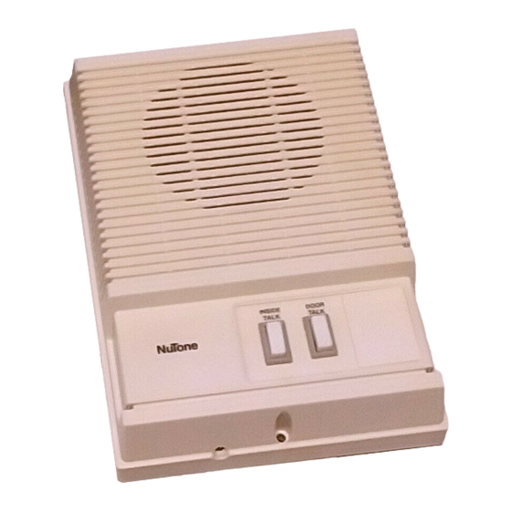
Door Com 3-Station Door-Answering Intercom
MODEL: IK-25 SERIES
Includes: Master Speaker, Remote Speaker, Door Speaker and Transformer
LOCATION
1. Locate the Inside Speakers wherever it is convenient. Install
speakers at an easy operating height – approximately 60" from
the floor.
2. Locate the Door Speaker on an even mounting surface close to
the door. The mounting surface should be wide enough for the
speaker. Mount the Door Speaker at a height for easy pushbutton
operation.
3. Try to locate the speaker where running the wires will not be a
problem.
4. IMPORTANT: Maximum cable length between Master and
Remote inside speakers is 100 ft (50 ft if a door release is
used). Maximum cable length between Door speaker and
Master speaker is 300 ft. Do not locate speakers back-to-
back on the same wall.
WIRING INSTALLATION AND
CONNECTIONS
1. Turn off the house power at its source and leave it off until
installation is complete.
2. All wiring must comply with local codes.
3. Carefully fasten wiring to wall studs and ceiling joists. Avoid
short circuits caused by staples, nails, or clips cutting
through the wiring's insulation.
WIRING CAUTIONS
NOTE: This section contains wiring instructions for a basic
system: transformer, master speaker, inside remote speaker, and
door speaker. If the system requires the optional door release or the
optional lighted door speaker pushbutton, see "Optional Door
Release," or "Optional Lighted Pushbutton."
TRANSFORMER WIRING
1. Install the supplied 16 volt transformer. Mount transformer to a
junction box or circuit breaker box. Do not mount the trans-
former in a high temperature area (i.e., attic, crawl space).
120vAC
TRANSFORMER
IW-2
16VAC
DOOR SPEAKER
®
MASTER STATION
GRAY
BLACK
WHITE
WHITE
IW-6 CABLE
BROWN
GREEN
BROWN
ORANGE
IW-2
READ & SAVE THESE INSTRUCTIONS!
INSTALLATION & OPERATING INSTRUCTIONS
2. Connect 120VAC house power wiring to the transformer's primary
leads.
3. Refer to Figure 1. Connect NuTone IW-2 (22 gauge,
two-conductor, twisted-pair, 100 ft max.) between the
transformer's secondary terminals and a BLACK and WHITE wire
at the Master Speaker.
DOOR SPEAKER WIRING
1. Refer to Figure 1. Run IW-2 cable (300 ft max.) between the
Door Speaker location and the Master Speaker location.
2. Connect the BROWN Door Speaker wires to the GREEN and
ORANGE Master Speaker wires.
MASTER AND REMOTE SPEAKER WIRING
IMPORTANT: NuTone cannot be responsible for improper
intercom operation that results from interference generated by
light dimmers, fluorescent lighting fixtures, and similar
electrical products, such interference must be corrected at the
source. As an aid to help reduce this interference, all remote
cables must be placed at least 12 inches from any A.C. power
wiring.
The Intercom System is designed to be used only with
NuTone specified wire. No other wire should be used. The use
of wire other than NuTone wire may result in faulty installation
and improper operation.
1. Run NuTone IW-6 (3-Twisted Pair, 6-wire, 22 gauge cable) from
the Master Speaker location to the Remote Inside Speaker
location. (Maximum cable length is 100 ft (50 ft if a door release is
used).
2. Refer to Figure 1. Connect the IW-6 color-coded wires to
matching color-coded wires at both the Master Speaker and the
Inside Remote Speaker. (i.e., orange to orange; orange/white to
orange/white, etc.). NOTE: If the Door Release option is not
used, do not connect the RED wires. See "Optional Door
Release," page 3.
INSIDE REMOTE STATION
ORANGE ORANGE
ORN/WHT ORN/WHT
BLACK
BLACK
BLK/WHT BLK/WHT
RED
(NOT USED)
RED/WHT RED/WHT
IW-6
CABLE
FIGURE 1
Advertisement

Related Manuals for NuTone IK-25 series


Summary of Contents for NuTone IK-25 series
- Page 1 The Intercom System is designed to be used only with 3. Carefully fasten wiring to wall studs and ceiling joists. Avoid NuTone specified wire. No other wire should be used. The use short circuits caused by staples, nails, or clips cutting of wire other than NuTone wire may result in faulty installation through the wiring’s insulation.
- Page 2 1. Twist the terminal base to unlock it from the pushbutton. Write name on card and insert into nameplate. Snap 2. Insert the bulb (NuTone PBL-2) into the terminal base. nameplate into place. Make sure each bulb wire contacts a socket plate.
- Page 3 Model IM-25SW door-release pushbutton at the inside as shown in Figure 8, (50 ft maximum). speakers and a NuTone Model DR-1 Door Release at the 2. Make wiring connections at the Remote Speaker as shown door. All are purchased separately.
-
Page 4: Talk Button
WARRANTIES OF MERCHANTABILITY OR FITNESS FOR A PARTICULAR PURPOSE. During this two year period, NuTone will, at its option, repair or replace, without charge, any product or part which is found to be defective under normal use and service. THIS WARRANTY DOES NOT EXTEND TO FLUORESCENT LAMP STARTERS OR TUBES, FILTERS, DUCT, ROOF CAPS, WALL CAPS AND OTHER ACCESSORIES FOR DUCTING.
Need help?
Do you have a question about the IK-25 series and is the answer not in the manual?
Questions and answers