Asus P5KPL-AM SE User Manual
Hide thumbs
Also See for P5KPL-AM SE:
- User manual (92 pages) ,
- Quick start manual (4 pages) ,
- User manual (62 pages)
Table of Contents
Advertisement
Quick Links
Advertisement
Table of Contents

Related Manuals for Asus P5KPL-AM SE


Summary of Contents for Asus P5KPL-AM SE
- Page 1 P5KPL-AM SE...
- Page 2 Product warranty or service will not be extended if: (1) the product is repaired, modified or altered, unless such repair, modification of alteration is authorized in writing by ASUS; or (2) the serial number of the product is defaced or missing.
-
Page 3: Table Of Contents
Contents Notices ......................vi Safety information ..................vii About this guide ..................viii P5KPL-AM SE specifications summary ............. x Chapter 1: Product introduction Welcome! ..................1-1 Package contents ................. 1-1 Special features ................1-1 1.3.1 Product highlights ............1-1 1.3.2 ASUS Special features ........... - Page 4 2.1.1 ASUS Update utility ............2-1 2.1.2 Creating a bootable floppy disk ........2-2 2.1.3 ASUS EZ Flash 2 utility ........... 2-3 2.1.4 AFUDOS utility ..............2-4 2.1.5 ASUS CrashFree BIOS 3 utility ........2-5 BIOS setup program ..............2-7 2.2.1...
- Page 5 Boot menu .................. 2-19 2.6.1 Boot Device Priority ............2-19 2.6.2 Boot Settings Configuration .......... 2-20 2.6.3 Security ................. 2-20 Tools menu ................. 2-22 2.7.1 ASUS EZ Flash 2 ............2-22 2.7.2 AI NET 2................ 2-22 Exit menu ..................2-22...
-
Page 6: Notices
Notices Federal Communications Commission Statement This device complies with Part 15 of the FCC Rules. Operation is subject to the following two conditions: • This device may not cause harmful interference, and • This device must accept any interference received including interference that may cause undesired operation. -
Page 7: Safety Information
Safety information Electrical safety • To prevent electrical shock hazard, disconnect the power cable from the electrical outlet before relocating the system. • When adding or removing devices to or from the system, ensure that the power cables for the devices are unplugged before the signal cables are connected. If possible, disconnect all power cables from the existing system before you add a device. -
Page 8: Conventions Used In This Guide
Refer to the following sources for additional information and for product and software updates. ASUS websites The ASUS website provides updated information on ASUS hardware and software products. Refer to the ASUS contact information. Optional documentation Your product package may include optional documentation, such as warranty flyers, that may have been added by your dealer. -
Page 9: P5Kpl-Am Se Specifications Summary
® Processors Compatible with Intel 05B / 05A / 06 processors ® Intel Hyper-Threading Technology ready ® (Refer to www.asus.com for Intel CPU support list) Chipset Northbridge: Intel ® Southbridge: Intel ICH7 ® Front Side Bus 1600(O.C.) / 1333 / 1066 / 800 / 533MHz... - Page 10 SFS (Stepless Frequency Selection) Overclocking Features - FSB turning from 133MHz up to 600MHz at 1MHz increment. Overclocking Protection: - ASUS C.P.R. (CPU Parameter Recall) BIOS features 8 Mb Flash ROM, AMI BIOS, PnP, DMI2.0, WfM2.0, ACPI V2.0a, SM BIOS 2.5 Manageability...
-
Page 11: Chapter 1: Product Introduction
Green ASUS This motherboard and its packaging comply with the European Union’s Restriction on the use of Hazardous Substances (RoHS). This is in line with the ASUS vision of creating environment-friendly and recyclable products/packaging to safeguard consumers’ health while minimizing the impact on the environment. - Page 12 PCs e.g., Gigabit LAN, 1394b, and high-speed RAID systems. FSB 1600 support (O.C.) ASUS’s exclusive overclocking design now unleashes the ultimate potential of the Intel Core ® ™2 processor. With the new Intel 45nm micro-architecture technology and FSB 1600 (O.C.) / 1333 / 1066 / 800 MHz, this motherboard allows you to enjoy the latest technology supported by one of the most powerful and energy efficient CPUs in the world.
-
Page 13: Asus Special Features
Simply restore corrupted BIOS data from USB flash disk The ASUS CrashFree BIOS 3 allows users to restore corrupted BIOS data from a USB flash disk containing the BIOS file. This utility saves users the cost and hassle of buying a replacement BIOS chip. -
Page 14: Before You Proceed
The illustration below shows the location of the onboard LED. SB_PWR P5KPL-AM SE Standy Power Powered Off P5KPL-AM SE Onboard LED Chapter 1: Product introduction... -
Page 15: Motherboard Overview
Place six screws into the holes indicated by circles to secure the motherboard to the chassis. Do not overtighten the screws! Doing so can damage the motherboard. Place this side towards the rear of the chassis P5KPL-AM SE ASUS P5KPL-AM SE... -
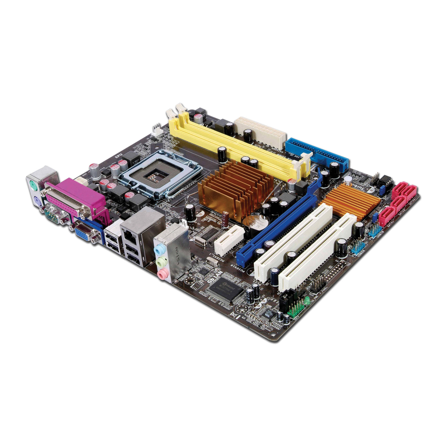
Page 16: Motherboard Layout
USB34 LAN1_USB12 Intel ® CHA_FAN AUDIO 8102EL PCIEX16 Lithium Cell Intel ® CMOS Power Super ICH7 P5KPL-AM SE PCIEX1_1 SPEAKER PCI1 CLRTC ALC662 BIOS USBPW5-8 F_PANEL SB_PWR USB56 USB78 PRI_IDE AAFP Refer to section 1.10 Connectors for more information about rear panel connectors and internal connectors. -
Page 17: Layout Contents
Contact your retailer immediately if the PnP cap is missing, or if you see any damage to the PnP cap/socket contacts/motherboard components. ASUS will shoulder the cost of repair only if the damage is shipment/ transit-related. -
Page 18: Installing The Cpu
To install a CPU: Locate the CPU socket on the motherboard. P5KPL-AM SE P5KPL-AM SE CPU socket 775 Before installing the CPU, ensure that the socket box is facing towards you and the load lever is on your left. Press the load lever with your thumb... - Page 19 (B) until it snaps into the retention tab. The motherboard supports Intel ® LGA775 processors with the Intel Enhanced Intel SpeedStep ® ® Technology (EIST) and Hyper- Threading Technology. Refer to the Appendix for more information on these CPU features. ASUS P5KPL-AM SE...
-
Page 20: Installing The Cpu Heatsink And Fan
Do not forget to connect CPU FAN PWM the CPU fan connector! CPU FAN IN Hardware monitoring errors CPU FAN PWR can occur if you fail to plug this connector. P5KPL-AM SE P5KPL-AM SE CPU fan connector 1-10 Chapter 1: Product introduction... -
Page 21: Uninstalling The Cpu Heatsink And Fan
Overview The motherboard comes with two Double Data Rate 2 (DDR2) Dual Inline Memory Modules (DIMM) sockets. The figure illustrates the location of the DDR2 DIMM sockets: P5KPL-AM SE P5KPL-AM SE 240-pin DDR2 DIMM sockets Channel Sockets Channel A DIMM_A1... -
Page 22: Memory Configurations
1.7.2 Memory configurations You may install 256 MB, 512 MB, 1 GB and 2 GB unbuffered non-ECC DDR2 DIMMs into the DIMM sockets. • You may install varying memory sizes in Channel A and Channel B. The system maps the total size of the lower-sized channel for the dual-channel configuration. Any excess memory from the higher-sized channel is then mapped for single-channel operation. - Page 23 • DDR2-667U 1G Hynix HY5PS12821BFP-E3 A • • 512MB AENEON AET660UD00-30DA98Z AENEON AET93F30DA 0552 • • 512MB AENEON AET660UD00-30DB97X AENEON AET93R300B 0634 • • AENEON AET760UD00-30DA98Z AENEON AET93F30DA8EE47414G 0540 • • (continued on the next page) ASUS P5KPL-AM SE 1-13...
- Page 24 DIMM support S S / Size Vendor Model Brand Component AENEON AET760UD00-30DA98Z AENEON AET93F30DA 0604 • • AENEON AET760UD00-30DB97X AENEON AET93R300B 0639 • • 512MB TAKEMS TMS51B264C081-665QI takeMS MS18T51280-3 • • 512MB TAKEMS TMS51B264C081-665AP takeMS MS18T51280-3S0627D • • TAKEMS TMS1GB264C081-665QI takeMS MS18T51280-3 •...
- Page 25 Kingbox EP512D21066PS Micron 6QD22D9GCT • • Visit the ASUS website at (www.asus.com) for the latest QVL. SS - Single-sided / DS - Double - sided DIMM support: • A*: Supports one module inserted into any slot as Single-channel memory configuration.
-
Page 26: Installing A Dimm
1.7.3 Installing a DIMM Unplug the power supply before adding or removing DIMMs or other system components. Failure to do so may cause severe damage to both the motherboard and the components. To install a DIMM: DDR2 DIMM notch Press the retaining clips outward to unlock a DDR2 DIMM socket. -
Page 27: Expansion Slots
This motherboard supports PCI Express x1 network cards, SCSI cards and other cards that comply with the PCI Express specifications. 1.8.5 PCI Express x16 slot This motherboard supports a PCI Express x16 graphics card that complies with the PCI Express specifications. ASUS P5KPL-AM SE 1-17... -
Page 28: Jumpers
Normal Clear RTC (Default) P5KPL-AM SE Clear RTC RAM • If the steps above do not help, remove the onboard battery and move the jumper again to clear the CMOS RTC RAM data. After the CMOS clearance, reinstall the battery. - Page 29 +5VSB P5KPL-AM SE (Default) P5KPL-AM SE USB Device Wake Up • The USB device wake-up feature requires a power supply that can provide 500mA on the +5VSB lead for the USB port. Otherwise, the system would not power up. • The total current consumed must NOT exceed the power supply capability (+5VSB) whether under normal condition or in sleep mode.
-
Page 30: Connectors
1.10 Connectors 1.10.1 Rear panel connectors PS/2 mouse port (green). This port is for a PS/2 mouse. LAN (RJ-45) port. Supported by Realtek 10/100 LAN controller, this port allows 10/100 connection to a Local Area Network (LAN) through a network hub. Refer to the table below for the LAN port LED indications. -
Page 31: Internal Connectors
RSATA_TXP1 RSATA_RXN2 RSATA_RXN1 P5KPL-AM SE RSATA_RXP2 RSATA_RXP1 P5KPL-AM SE SATA connectors (ICH10R ® right angle side Connect the right-angle side of SATA signal cable to SATA device. You may also connect the right-angle side of SATA cable to the onboard SATA port to avoid mechanical conflict with huge graphics cards. - Page 32 P5KPL-AM SE IDE connector Optical drive audio connector (4-pin CD) These connectors allow you to receive stereo audio input from sound sources such as a CD-ROM, TV tuner, or MPEG card. P5KPL-AM SE P5KPL-AM SE Internal audio connector 1-22 Chapter 1: Product introduction...
- Page 33 Never connect a 1394 cable to the USB connectors. Doing so will damage the motherboard! You can connect the front panel USB cable to the ASUS Q-Connector (USB, blue) first, and then install the Q-Connector (USB) to the USB connector onboard if your chassis supports front panel USB ports.
- Page 34 +12V P5KPL-AM SE P5KPL-AM SE fan connectors Only the CPU_FAN connector support the ASUS Advanced Q-Fan feature. Speaker connector (4-pin SPEAKER) This 4-pin connector is for the chassis-mounted system warning speaker. The speaker allows you to hear system beeps and warnings.
- Page 35 +3 Volts PIN 1 P5KPL-AM SE ATX power connectors • For a fully configured system, we recommend that you use a power supply unit (PSU) that complies with ATX 12 V Specification 2.0 (or later version) and provides a minimum power of 400 W.
-
Page 36: System Panel Connector
PIN 1 P5KPL-AM SE HD_LED RESET P5KPL-AM SE System panel connector System power LED (2-pin PWRLED) • This 2-pin connector is for the system power LED. Connect the chassis power LED cable to this connector. The system power LED lights up when you turn on the system power, and blinks when the system is in sleep mode. -
Page 37: Software Support
Click an item to install If Autorun is NOT enabled in your computer, browse the contents of the Support DVD to locate the file ASSETUP.EXE from the BIN folder. Double-click the ASSETUP.EXE to run the DVD. ASUS P5KPL-AM SE 1-27... - Page 38 1-28 Chapter 1: Product introduction...
-
Page 39: Managing And Updating Your Bios
The following utilities allow you to manage and update the motherboard Basic Input/Output System (BIOS) setup. ASUS EZ Flash 2 (Updates the BIOS in DOS mode using a floppy disk or USB flash disk.) ASUS AFUDOS (Updates the BIOS in DOS mode using a bootable floppy disk.) ASUS CrashFree BIOS 3 (Updates the BIOS using a bootable floppy disk, USB flash disk or the motherboard support DVD when the BIOS file fails or gets corrupted.) -
Page 40: Creating A Bootable Floppy Disk
ASUSUpdate. Select Update BIOS from the Internet from the drop-down menu, then click Next. Select the ASUS FTP site nearest you to avoid network traffic, or click Auto Select then click Next. From the FTP site, select the BIOS version that you wish to download then click Next. -
Page 41: Asus Ez Flash 2 Utility
ASUS EZ Flash 2 utility The ASUS EZ Flash 2 feature allows you to update the BIOS without having to go through the long process of booting from a floppy disk and using a DOS-based utility. The EZ Flash 2 utility is built in the BIOS chip so it is accessible by pressing <Alt>... -
Page 42: Afudos Utility
Updating the BIOS file To update the BIOS file using the AFUDOS utility: Visit the ASUS website (at www.asus.com) and download the latest BIOS file for the motherboard. Save the BIOS file to a bootable floppy disk. We recommend that you write the BIOS filename on a piece of paper. You will need to key in the exact BIOS filename at the DOS prompt later. -
Page 43: Asus Crashfree Bios 3 Utility
2.1.5 ASUS CrashFree BIOS 3 utility The ASUS CrashFree BIOS 3 is an auto recovery tool that allows you to restore the BIOS file when it fails or gets corrupted during the updating process. You can update a corrupted BIOS file using the motherboard support DVD, a floppy disk or a USB flash disk that contains the updated BIOS file. - Page 44 Restart the system after the utility completes the updating process. The recovered BIOS may not be the latest BIOS version for this motherboard. Visit the ASUS website (at www.asus.com) to download the latest BIOS file. Recovering the BIOS from a USB flash disk To recover the BIOS from a USB flash disk: Insert a USB flash disk that contains BIOS file to the USB port.
-
Page 45: Bios Setup Program
Restart the system after the utility completes the updating process. • Only the USB flash disk with FAT 32/16 format and single partition can support ASUS CrashFree BIOS 3. The device size should be smaller than 8GB. • DO NOT shut down or reset the system while updating the BIOS! Doing so can cause... -
Page 46: Bios Menu Screen
2.2.1 BIOS menu screen Menu items Menu bar Configuration fields General help BIOS SETUP UTILITY Main Advanced Power Boot Tools Exit Use [ENTER], [TAB] or System Time [14:14:35] [SHIFT-TAB] to select System Date [Wed 04/16/2008] a field. Use [+] or [-] to configure system time. -
Page 47: Menu Items
Pop-up window <Page Up> /<Page Down> keys to Scroll bar display the other items on the screen. 2.2.9 General help At the top right corner of the menu screen is a brief description of the selected item. ASUS P5KPL-AM SE... -
Page 48: Main Menu
Main menu When you enter the BIOS Setup program, the Main menu screen appears, giving you an overview of the basic system information. Refer to section 2.2.1 BIOS menu screen for information on the menu screen items and how to navigate through them. BIOS SETUP UTILITY Main Advanced... -
Page 49: Sata 1 And Sata 2
Storage Configuration The items in this menu allow you to set or change the configurations for the SATA devices installed in the system. Select an item then press <Enter> if you want to configure the item. ASUS P5KPL-AM SE 2-11... -
Page 50: System Information
ATA/IDE Configuration [Enhanced] Configuration options: [Disabled] [Compatible] [Enhanced] Enhanced Mode Support On [S-ATA] Configuration options: [S-ATA+P-ATA] [S-ATA] [P-ATA] IDE Detect Time Out [35] Selects the time out value for detecting ATA/ATAPI devices. Configuration options: [0] [5] [10] [15] [20] [25] [30] [35] 2.3.6 System Information This menu gives you an overview of the general system specifications. - Page 51 Manually set memory voltage or set to Auto for safe mode. Configuration options: [Auto] [1.80V] [2.00V] [2.25V] VTT_CPU Over Voltage [Auto] Manually set FSB Termination Voltage or set to Auto for safe mode. Configuration options: [Auto] [1.2V] [1.3V] ASUS P5KPL-AM SE 2-13...
-
Page 52: Usb Configuration
1.25V Over Voltage [Auto] Manually set MCH Chipset Voltage or set to Auto for safe mode. Configuration options: [Auto] [1.25V] [1.4V] 1.5V Over Voltage [Auto] Manually set ICH Chipset Voltage or set to Auto for safe mode. Configuration options: [Auto] [1.5V] [1.6V] 2.4.2 USB Configuration The items in this menu allows you to change the USB-related features. -
Page 53: Chipset
Allows you to decide which graphics controller to use as the primary boot device. Configuration options: [IGD] [PCI/IGD] [PCI/PEG] [PEG/IGD] [PEG/PCI] Internal Graphics Mode Select [Enabled, 8MB] Allows you to select the amout of system memory used by the Interanal graphics device. Configuration options: [Disabled] [Enabled, 1MB] [Enabled, 8MB] ASUS P5KPL-AM SE 2-15... -
Page 54: Onboard Devices Configuration
PEG Port Configuration PEG Force x1 [Disabled] Allows you to enable or disable the PEG Forec x 1. Configuration options: [Enabled] [Disabled] Video Function Configuration DVMT Mode Select [DVMT Mode] Allows you to select the DVMT Mode. Configuration options: [Fixed Mode] [DVMT Mode] DVMT/FIXED Memory [256MB] Allows you to select the amount of the DVMT/FIXED Memory. -
Page 55: Power Menu
[Auto] - Detected by OS. 2.5.2 ACPI 2.0 Support [Disabled] Allows you to add more tables for Advanced Configuration and Power Interface (ACPI) 2.0 specifications. Configuration options: [Disabled] [Enabled] ASUS P5KPL-AM SE 2-17... -
Page 56: Acpi Apic Support
2.5.3 ACPI APIC Support [Enabled] Allows you to enable or disable the Advanced Configuration and Power Interface (ACPI) support in the Advanced Programmable Interrupt Controller (APIC). When set to Enabled, the ACPI APIC table pointer is included in the RSDT pointer list. Configuration options: [Disabled] [Enabled] 2.5.4 APM Configuration... -
Page 57: Boot Menu
These items specify the boot device priority sequence from the available devices. The number of device items that appears on the screen depends on the number of devices installed in the system. Configuration options: [Hard Drive] [Removable Dev.] [ATAPI CD-ROM] [Disabled] ASUS P5KPL-AM SE 2-19... -
Page 58: Boot Settings Configuration
POST items. Configuration options: [Disabled] [Enabled] Full Screen Logo [Enabled] This allows you to enable or disable the full screen logo display feature. Configuration options: [Disabled] [Enabled] Set this item to [Enabled] to use the ASUS MyLogo2 feature. ™ AddOn ROM Display Mode [Force BIOS] Sets the display mode for option ROM. -
Page 59: Change User Password
Password Check [Setup] When set to [Setup], BIOS checks for user password when accessing the Setup utility. When set to [Always], BIOS checks for user password both when accessing Setup and booting the system. Configuration options: [Setup] [Always] ASUS P5KPL-AM SE 2-21... -
Page 60: Tools Menu
2.7.1 ASUS EZ Flash 2 Allows you to run ASUS EZ Flash 2. When you press <Enter>, a confirmation message appears. Use the left/right arrow key to select between [Yes] or [No], then press <Enter> to confirm your choice. Please see section 2.1.3 for details. -
Page 61: Discard Changes
When you select this option or if you press <F5>, a confirmation window appears. Select OK to load default values. Select Exit & Save Changes or make other changes before saving the values to the non-volatile RAM. ASUS P5KPL-AM SE 2-23... - Page 62 2-24 Chapter 2: BIOS setup...
Need help?
Do you have a question about the P5KPL-AM SE and is the answer not in the manual?
Questions and answers