Advertisement
Table of Contents
- 1 General Information
- 2 Table of Contents
- 3 Contents/Declaration
- 4 Specification/Guarantee
- 5 Power Supply
- 6 General Safety Instructions
- 7 Additional Safety Rules
- 8 Unpacking and Checking Contents
- 9 Getting to Know Your Bandsaw
- 10 Assembly
- 11 Operation and Use
- 12 Operation and Use
- 13 Tips on Using Your Bandsaw
- 14 Tips on Using Your Bandsaw
- 15 Maintenance/Optional Accessories
- Download this manual
360mm BANDSAW
STOCK No.36761
PART No.BS355A
• INSTRUCTIONS •
IMPORTANT: PLEASE READ THESE INSTRUCTIONS CAREFULLY TO ENSURE THE
SAFE AND EFFECTIVE USE OF THIS TOOL.
12/2000
GENERAL INFORMATION
This manual has been compiled by Draper Tools and is an integrated part of the power tool equipment, which
should be kept with the machine.
This manual describes the purpose for which this tool has been designed and contains all the necessary
information to ensure its correct and safe use.We recommend that this manual is read before any operation of
the machine, before performing any kind of adjustment to the machine, and prior to any maintenance tasks. By
following all the general safety instructions contained in this manual, it will ensure both machine and operator
safety, together with longer life of the tool itself.
All photographs and drawings in this manual are supplied by Draper Tools to help illustrate the operation of the
machine.
Whilst every effort has been made to ensure accuracy of information contained in this manual, the Draper Tool
policy of continuous improvement determines the right to make modifications without prior warning.
Advertisement
Table of Contents

Related Manuals for Draper BS355A


Summary of Contents for Draper BS355A
-
Page 1: General Information
12/2000 GENERAL INFORMATION This manual has been compiled by Draper Tools and is an integrated part of the power tool equipment, which should be kept with the machine. This manual describes the purpose for which this tool has been designed and contains all the necessary information to ensure its correct and safe use.We recommend that this manual is read before any operation of... -
Page 2: Table Of Contents
Operation and Use ..................9-12 Tips on Using Your Bandsaw ..............13-14 Maintenance/Optional Accessories..............15 DECLARATION OF CONFORMITY Draper Tools Ltd. Hursley Road, Chandler’s Ford, Eastleigh, Hampshire. SO53 1YF. England. Declare under our sole responsibility that the product: Stock No:- 36761. Part No:- BS355A. -
Page 3: Specification/Guarantee
This guarantee applies in lieu of any other guarantee expressed or implied and variations of its terms are not authorised. Your Draper guarantee is not effective unless you can produce upon request a dated receipt or invoice to verify your proof of purchase within the 12 month period. -
Page 4: Power Supply
(i.e. red). Fuse covers are available from your Draper Tools stockist. If the fitted plug is not suitable, it should be cut off and destroyed. *The end of the cable should now be suitably prepared and the correct type of plug fitted. -
Page 5: General Safety Instructions
IMPORTANT Draper Tools Limited recommends that this machine should not be modified or used for any application other than that for which it was designed. If you are unsure of its relative applications do not hesitate to contact us in writing and we will advise you. -
Page 6: Additional Safety Rules
ADDITIONAL SAFETY RULES FOR BANDSAWS/DISCS AND STRIP SANDERS 1. Lower the blade guard to within 14. Permanently fix your bandsaw to a approximately 3mm above the bench before performing cutting material being cut. operations. (See ‘Fastening to a Workbench’, page 9). 2. -
Page 7: Unpacking And Checking Contents
Refer to Fig.1. Check that all the parts are present. If any parts are damaged or are missing, please call the Draper Helpline on (023) 8049 4344. Fig.1. - 6 -... -
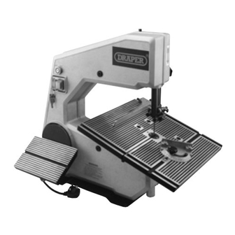
Page 8: Getting To Know Your Bandsaw
GETTING TO KNOW YOUR BANDSAW Fig.2. Fig.2. 1. No Volt switch 12. Blade guard 2. Drive wheel & sanding disc 13. Tracking wheel 3. Sanding guard (not shown) 14. Tension bolt 4. Sanding table 15. Height adjustment lock knob 5. Sanding table lock knob 16. -
Page 9: Assembly
ASSEMBLY Your bandsaw is supplied assembled except Fig.3. for the work and sanding table. To assemble the worktable to the bandsaw: 1. Remove the table lock knob , spring and spring support bush from the table support at the rear of the bandsaw (Fig.3). -
Page 10: Operation And Use
OPERATION & USE ON/OFF SWITCH Fig.6. When key is in the off/locked position, it will prevent unauthorized operation of the bandsaw (Fig.6). Fig.7. The bandsaw is fitted with a no volt switch. In the event of a power supply failure the bandsaw will have to be manually re-started (Fig.7). - Page 11 OPERATION & USE CHANGING BLADES Fig.9. 1. Turn the main power switch off and disconnect from the power supply. 2. Remove front cover. 3. Remove the upper blade guard loosen locking screw and adjust the upper support bearing away from the blade (Fig.9).
- Page 12 OPERATION & USE MITRE GUIDE Fig.13. Most cross cut work, especially with small pieces of material are more easily controlled with the aid of the mitre guide . The guide is graduated to 45˚ for assistance in cutting both left and right hand angles. Fig.13. RIP FENCE True straight line rip cutting is best done by guiding the work against the rip fence...
-
Page 13: Operation And Use
(See CHANGING SPEEDS page 9). Replacement sandpaper discs are available Fig.17. from the Draper Stockist (see optional accessories page15). They can be obtained in four grits and are self-adhesive so that no glue is required to fix them to the aluminium disc. -
Page 14: Tips On Using Your Bandsaw
TIPS ON USING YOUR BANDSAW WORKTABLE TIPS ABOUT BANDSAW BLADES The worktable is a 400x400mm The size of a band saw blade is denoted aluminium die-casting. It supports the by width, length and thickness. This material being cut and is grooved to bandsaw uses blades which are 1785mm accept a mitre guide and rip fence. -
Page 15: Tips On Using Your Bandsaw
TIPS ON USING YOUR BANDSAW For all cutting operations the upper the table it will help support the work blade guard should be adjusted to just against slip. The width of cut indicator clear the work being cut (approx. 3mm shows the distance between the blade ⁄... -
Page 16: Maintenance/Optional Accessories
MAINTENANCE CHANGING TYRES Eventually the rubber tyres on the bandsaw wheels will wear due to the constant contact of the sharp teeth of the blade. Remove the blade, lift the edge of the tyre with a small screwdriver and the tyre can be worked off the wheel easily.We recommend that the three tyres be changed at the same time. - Page 17 NOTES - 16 -...
- Page 18 NOTES - 17 -...
- Page 19 NOTES - 18 -...
- Page 20 ©Published by Draper Tools Ltd. No part of this publication may be reproduced, stored in a retrieval system or transmitted in any form or by any means, electronic, mechanical photocopying, recording or otherwise without prior permission in writing from Draper Tools Ltd.
Need help?
Do you have a question about the BS355A and is the answer not in the manual?
Questions and answers