Advertisement
Quick Links
Manuel d'utilisation et d'entretien
Foreuse de chantier
Manual de Instrucciones
Taladradora de obra
Betriebs-und Wartungsanleitung
Baustellen-Bohrmaschine
Manual de Instrucoes
Perfuradora de obra
DS160C
Asia Pacific
Manuale di Istruzioni
Trapanatrice da cantiere
Operating Instructions
Drilling Machine
Gebruiksaanwijzing
Verplaatsbare Boormachine
Bruksanvisning och Underhallsmanual
Borrmaskin
113
Advertisement

Related Manuals for Husqvarna DS160C


Summary of Contents for Husqvarna DS160C
- Page 1 DS160C Asia Pacific Manuel d’utilisation et d’entretien Manuale di Istruzioni Foreuse de chantier Trapanatrice da cantiere Manual de Instrucciones Operating Instructions Taladradora de obra Drilling Machine Betriebs-und Wartungsanleitung Gebruiksaanwijzing Baustellen-Bohrmaschine Verplaatsbare Boormachine Manual de Instrucoes Bruksanvisning och Underhallsmanual Perfuradora de obra...
- Page 3 WARNING Some dust created by power sanding, sawing, grinding, drilling and other construction activities contains chemicals known to cause cancer, birth defects or other reproductive harm. Some examples of these chemicals are: ·Lead from lead-base paints, ·Crystalline silica from bricks and cement and other masonry products and ·Arsenic and Chromium from chemically treated lumber.
- Page 4 PREFACE TO THE MANUAL These operating instructions apply exclusively to drill stand, type DS 160 C. Please also read the operating instructions that accompany your drill motor to verify their compatibility and not to exceed the limitations of the DS 160 C drill stand. Usage to the Intended Purpose The drill stand is designed exclusively for core drilling in concrete, asphalt, brickwork or similar building materials.
- Page 5 ·Prevent accidents due to unsuitable use, by an untrained person, during maintenance, repairs, overhauls, handling or transport ·Improve the reliability and durability of the machine ·Ensuring correct use, regular maintenance and rapid repair in order to reduce stoppage times and repair cost. The manual should always be available at the place of work.
- Page 6 ·Competent staff (qualifications, age, training) who have read and understood the manual in detail before starting work: any electrical, mechanical or other problem should be investigated by a qualified maintenance engineer (electrician, maintenance manager, approved dealer, etc). ·That the warnings and instructions marked on the machine are followed (adequate personal protection, correct use, general safety instructions, etc).
- Page 7 3. Assembly Align holes on the wheel assembly (1) with the tapped holes on rear of the base plate (2). Insert bolts through lockwashers (4), then insert bolts through wheel assembly and screw onto base plate. 4. Description and Features of the Drill Stand Tapered roller carriage.
- Page 8 The operator must wear protective clothing appropriate to the work he is doing. We recommend that this includes both eye and ear protection. Any person not involved in the work should leave the working area. Use core bits which are suitable for the work to be done. 7.
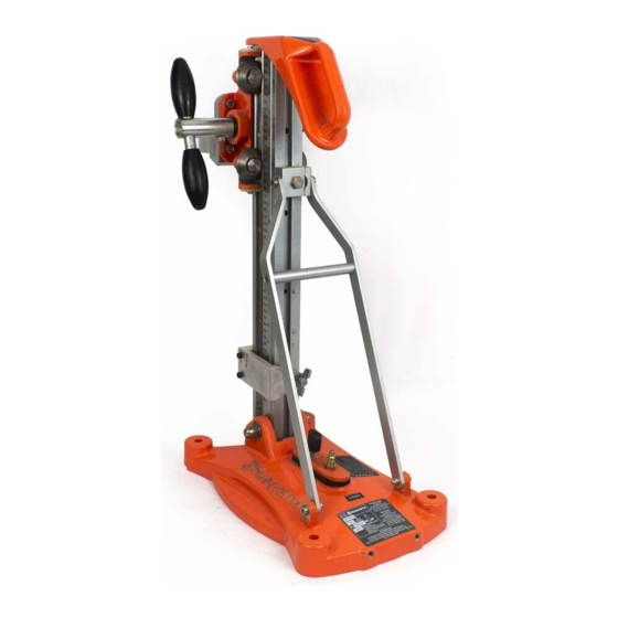
- Page 9 10. Designation of the Components Carrying Handle Carriage Feed Handle Level and Plum Indicator Carriage Brake Back Support Drill Motor Mount Gear Rack Depth and Angle Scale Angle Column Lock Screw Wheel Assembly (Removable) Leveling Screws Vacuum Cap (Removable) Base Plate w/ Integrated Vacuum Vacuum Quick Disconnect...
- Page 10 11. Operation Positions The drill stand can be used for drilling ceilings, floors and walls. Individual safety instructions for each area of applications as described in the following chapters must be observed and complied with. The three main drilling directions (area of application) are: Floor position: The feed direction is vertical and downward.
- Page 11 Drill a hole for the anchor at a distance of 292 mm ( X ) from the hole center. 1 Nut and Washer Drive the impact anchor and secure. Screw in the all thread rod (2). 2 All Thread Rod Slip on the base plate (4) over the thread rod.
- Page 12 13. Setting the Angle of the Column Remove the column lock bolt (1) Loosen bolt on back support bracket (2). The column can now be pulled into the desired position, 0 to 45 degrees. Side decal provides approximate measurements. If greater precision is required use alternate measuring techniques.
- Page 13 16. Maintenance For details of maintenance work required for the drill motor, please refer to the enclosed motor manufacturer’s documentation. Routine Checks Check electrical connections routinely before each use. The following routine checks should be carried out monthly: Check that all screws and fastening elements are properly secure. Check the feed handle for easy movement.
- Page 14 Wear Cylinders Using a 4mm allen wrench, turn each of the 4 setscrews (4) clockwise until the nylatron wear cylinders (5) are in slight contact with the column. Side Cleaning Plates Loosen each of the 4 cleaning plate capscrews (6) using a 3mm allen wrench and slide the cleaning plate (7) so it is in contact with the column wear plates.
- Page 15 24 25 26 27 20 19 18...
- Page 16 Drill Base Casting 541404783 Complete M16x70 Socket Head Shoulder Screw 541404144 Drill Operating Instruction Decal 541404098 Vacuum Cap Assembly 541404110 Complete M10x1.5 Nut 541404145 Leveling Screw 541404080 Serial Number Decal 541404099 Husqvarna Decal 542190734 M6 Allen Wrench 541404153 Not Shown...
- Page 17 15 16 17 12 13 20 21 *6.1 *7.1 7.3 7.4...
- Page 18 Item Description Part Number Comments Drill Carriage 541404784 Adaptor Plate 541404029 Drill Collar 541404030 541404031 M8x25 Socket Head Capscrew 541404126 Locking Mechanism 541404114 Complete Knob 541404087 Pin Retainer 541404085 Compression Spring 541404089 541404086 Spring Pin 2mmx16mm 541404088 Travel Lever Assembly 541404101 Complete Travel Lever...
- Page 19 Item Description Part Number Comments Column 541404050 M3x8 Socket Head, Flat Head Screw 541404137 Depth Measurement Decal 541404054 Angle Measurement Decal 541404055 Wear Plate 541404052 Rack 541404051 M4x8 Socket Head Capscrew 541404135 Carriage Stop 541404053 M6x25 Socket Head Capscrew 541404136 Column Spacer 541404081 M8x90 Socket Head Capscrew...
- Page 20 Item Description Part Number Comments Roller 541404037 Spacer 541404036 Bearing 12mmI.D.x24mmO.D.x6mm 541404034...
- Page 21 Item Description Part Number Comments Angle Support Member 541404062 Angle Support Spacer 541404064 T-Washer Retainer 541404065 M6x20 Flat Socket Head Screw 541404138 M8 Socket Head Shoulder Screw 541404139 Angle Support Bushing 541404063...
- Page 22 Item Description Part Number Comments Knob w/Stud 541404073 1/8 NPT Male Fitting 541404071 Ball Detent 541404072 Vacuum Cap 541404068 Vacuum Cap Gasket 541404070...
- Page 23 All warranty claims will be determined after inspection at a designated facility. Write or call Husqvarna at 17400 W. 119th Street, Olathe, KS 66061, 800-365-5040, for instructions. The customer must prepay the freight and absorb any labor expense required to return or replace a product submitted to Husqvarna for warranty consideration.
- Page 24 The warranty is limited to the free of charge replacement of parts recognised as defective by HUSQVARNA CONSTRUCTION PRODUCTS (excluding wear components and consumables) providing the repair is made within after-sales service of HUSQVARNA CONSTRUCTION PRODUCTS or a recognised HUSQVARNA CONSTRUCTION PRODUCTS repair centre. The manufacturer is not responsible for any direct or indirect material or immaterial, damages caused to persons or things by failure of the machine or the non operation of the machine.