Table of Contents
Advertisement
Available languages
Available languages
TABLE OF CONTENTS
Service Information . . . . . . . . . . . . . . . . . . . . . . . . . . . . . .1
Rules for Safe Operation . . . . . . . . . . . . . . . . . . . . . . . . . .2
Know Your Unit . . . . . . . . . . . . . . . . . . . . . . . . . . . . . . . . .4
Assembly Instructions . . . . . . . . . . . . . . . . . . . . . . . . . . . .5
Oil and Fuel Information . . . . . . . . . . . . . . . . . . . . . . . . . . .6
Starting/Stopping Instructions . . . . . . . . . . . . . . . . . . . . . .8
Operating Instructions . . . . . . . . . . . . . . . . . . . . . . . . . . . .9
Maintenance and Repair Instructions . . . . . . . . . . . . . . .10
Cleaning and Storage . . . . . . . . . . . . . . . . . . . . . . . . . . .13
Troubleshooting Chart . . . . . . . . . . . . . . . . . . . . . . . . . . .14
Specifications . . . . . . . . . . . . . . . . . . . . . . . . . . . . . . . . .15
Warranty Information . . . . . . . . . . . . . . . . . . . . . . . . . . . .16
Parts List . . . . . . . . . . . . . . . . . . . . . . . . . . . . . . . . . . . .E16
WARNING:
When using the unit, you must follow
the safety rules. Please read these instructions
before operating the unit in order to ensure the
safety of the operator and any bystanders. Please
keep these instructions for later use.
P/N 769-02885
Operator's Manual
4-Cycle Gasoline Lawn Edger
TBE515
SAVE THESE INSTRUCTIONS
For service call 1-800-828-5500 in the United States, or
1-800-668-1238 in Canada to obtain a list of authorized service
dealers near you. For more details about your unit, visit our
website at www.troybilt.com.
DO NOT RETURN THE UNIT TO THE RETAILER. PROOF OF
PURCHASE WILL BE REQUIRED FOR WARRANTY
SERVICE.
THIS PRODUCT IS COVERED BY ONE OR MORE U.S.
PATENTS. OTHER PATENTS PENDING.
Service on this unit both within and after the warranty period
should be performed only by an authorized and approved
service dealer.
SPARK ARRESTOR NOTE
NOTE: For users on U.S. Forest Land and in the states of
California, Maine, Oregon and Washington. All U.S. Forest
Land and the state of California (Public Resources Codes 4442
and 4443), Oregon and Washington require, by law that certain
internal combustion engines operated on forest brush and/or
grass-covered areas be equipped with a spark arrestor,
maintained in effective working order, or the engine be
constructed, equipped and maintained for the prevention of
fire. Check with your state or local authorities for regulations
pertaining to these requirements. Failure to follow these
requirements could subject you to liability or a fine. This unit is
factory equipped with a spark arrestor. If it requires
replacement, ask your LOCAL SERVICE DEALER to install the
Accessory Part #753-05297 Spark Arrestor Kit.
CALIFORNIA PROPOSITION 65 WARNING
WARNING
THE ENGINE EXHAUST FROM THIS PRODUCT CONTAINS
CHEMICALS KNOWN TO THE STATE OF CALIFORNIA TO
CAUSE CANCER, BIRTH DEFECTS OR OTHER
REPRODUCTIVE HARM.
All information, illustrations, and specifications in this manual
are based on the latest product information available at the
time of printing. We reserve the right to make changes at any
time without notice.
Copyright© 2007 MTD SOUTHWEST INC, All Rights Reserved.
(2/07)
Advertisement
Chapters
Table of Contents

Related Manuals for Troy-Bilt TBE515


Summary of Contents for Troy-Bilt TBE515
- Page 1 Operator’s Manual 4-Cycle Gasoline Lawn Edger TBE515 SAVE THESE INSTRUCTIONS For service call 1-800-828-5500 in the United States, or 1-800-668-1238 in Canada to obtain a list of authorized service dealers near you. For more details about your unit, visit our website at www.troybilt.com.
- Page 2 RULES FOR SAFE OPERATION • IMPORTANT SAFETY INSTRUCTIONS • • Do not overreach, take extra care when working on steep slopes READ ALL INSTRUCTIONS BEFORE OPERATING or inclines. Always keep proper footing and balance. WARNING: When using the unit, the safety rules •...
- Page 3 RULES FOR SAFE OPERATION SAFETY AND INTERNATIONAL SYMBOLS This operator's manual describes safety and international symbols and pictographs that may appear on this product. Read the operator's manual for complete safety, assembly, operating and maintenance and repair information. SYMBOL MEANING SYMBOL MEANING •...
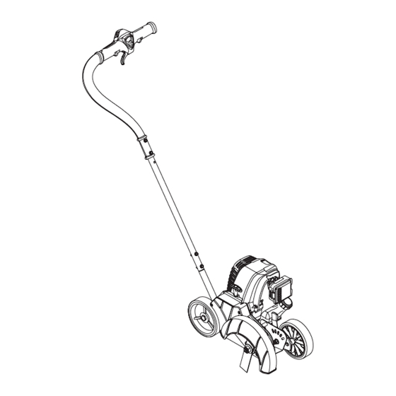
- Page 4 KNOW YOUR UNIT APPLICATIONS • Edging along paths, driveways, rockeries, etc. On/Off Switch Blade Clutch Lock-Out 3-Position Throttle Control Muffler Blade Clutch Lever Oil Plug Gas Tank Spark Plug Starter Rope Grip Choke Lever Air Filter Cover Depth Adjustment Lever Wheel Wheel Edger Blade...
- Page 5 ASSEMBLY INSTRUCTIONS HANDLE ASSEMBLY Self-Tapping Bolts Screws 1. Remove the unit from the box. 2. Place the 2-holed end of the straight metal shaft over the shaft base on the unit and align the holes (Fig. 1). 3. Insert the two self-tapping screws (1/4” x 1-1/4”) into these holes (Fig.
-
Page 6: Oil And Fuel Information
OIL AND FUEL INFORMATION 4. Pour the entire bottle of oil into the oil fill hole (Fig. 6). WARNING: OVERFILLING OIL CRANKCASE MAY CAUSE SERIOUS PERSONAL INJURY. Check and maintain the proper oil level in the crank case; it is important and cannot be overemphasized. - Page 7 OIL AND FUEL INFORMATION FUELING THE UNIT WARNING: Add fuel in a clean, well ventilated Gas Can Spout outdoor area. Wipe up any spilled fuel immediately. Avoid creating a source of ignition for spilt fuel. Do not start the engine until fuel vapors dissipate. WARNING: Gasoline is extremely flammable.
-
Page 8: Starting/Stopping Instructions
STARTING/STOPPING INSTRUCTIONS Choke Lever Primer Bulb WARNING: Operate this unit only in a well- ventilated outdoor area. Carbon monoxide exhaust fumes can be lethal in a confined area. WARNING: Avoid accidental starting. Make sure you are in the starting position when pulling the starter rope (Fig. - Page 9 OPERATING INSTRUCTIONS HOLDING THE UNIT WARNING: Always wear eye, hearing, foot and Thumb body protection to reduce the risk of injury when operating this unit. Wheel Before operating the unit, stand in the operating position (Fig. 12). Check for the following: Depth •...
-
Page 10: Maintenance And Repair Instructions
If you feel your Perform these required maintenance procedures at the engine is in need of this inspection, refer service to a Troy-Bilt or frequency stated in the table. These procedures should also other qualified service dealer for repair. - Page 11 MAINTENANCE AND REPAIR INSTRUCTIONS CHECKING THE OIL LEVEL The importance of checking and maintaining the proper oil level in the crankcase cannot be overemphasized. Check oil before each use: Fill Level 1. Stop the engine and allow oil to drain into the crankcase. 2.
- Page 12 MAINTENANCE AND REPAIR INSTRUCTIONS ROCKER ARM CLEARANCE This requires disassembly of the engine. If you feel unsure or unqualified to perform this, take the unit to an authorized service center. NOTE: Inspect the valve to rocker arm clearance with a feeler gauge after the first 10 hours of operation and every 25 hours of operation.
- Page 13 MAINTENANCE AND REPAIR INSTRUCTIONS 7. Slide the feeler gauge between the rocker arm and the SPARK ARRESTOR MAINTENANCE valve return spring. Measure the clearance between the Remove the rear engine cover. See Rocker Arm Clearance. valve stem and rocker arm (Fig. 29). Measure both the 2.
- Page 14 TROUBLESHOOTING LE MOTEUR REFUSE DE DÉMARRER C A U S E A C T I O N Empty fuel tank Fill fuel tank with new fuel Primer bulb wasn't pressed enough Press primer bulb fully and slowly 10 times Old fuel Drain gas tank and add fresh fuel Fouled spark plug Replace or clean the spark plug...
- Page 15 SPECIFICATIONS ENGINE* Engine Type.................................. Air-Cooled, 4-Cycle Displacement ..................................1.8 cu. in. (29 cc) Operating RPM ................................... 6,800+ rpm Idle Speed RPM ................................2,800 - 3,600 rpm Ignition Type....................................Electronic On/Off Stop Control ..................................Momentary Valve clearance............................0.003–0.006 in. (0.076–0.152 mm) Spark Plug Gap ................................
- Page 16 MANUFACTURER’S LIMITED WARRANTY FOR: The limited warranty set forth below is given by Troy-Bilt LLC No implied warranty, including any implied warranty of (“Troy-Bilt”) with respect with new merchandise purchased and merchantability or fitness for a particular purpose, applies used in the United States, its possessions and territories.
-
Page 17: Table Of Contents
Manuel de L'utilisateur Coupe-bordures à 4 temps à essence TBE515 CONSERVEZ CES INSTRUCTIONS Obtenez la liste des concessionnaires agréés appelez le 1-800- 828-5500 aux États-Unis ou le 1-800-668-1238 au Canada. Pour de plus amples informations à propos de votre appareil, visitez www.troybilt.com. -
Page 18: Consignes De Sécurité
CONSIGNES DE SÉCURITÉ • IMPORTANTES CONSIGNES DE SÉCURITÉ • LISEZ TOUTES LES INSTRUCTIONS AVANT L'UTILISATION vous toujours bien campé, en position d'équilibre. • Prenez soin de bien lire et comprendre le manuel de l'appareil • Tenez toujours l'appareil des deux mains lorsqu’il est en qui alimente cet accessoire. - Page 19 CONSIGNES DE SÉCURITÉ SYMBOLES DE SÉCURITÉ ET INTERNATIONAUX Ce manuel de l'utilisateur décrit les symboles et pictogrammes de sécurité et internationaux pouvant apparaître sur ce produit. Consultez le manuel de l'utilisateur pour les informations concernant la sécurité, le montage, le fonctionnement, l'entretien et les réparations. SYMBOLE SIGNIFICATION SYMBOLE...
-
Page 20: Familiarisez-Vous Avec Votre Appareil
FAMILIARISEZ-VOUS AVEC L’APPAREIL APPLICATIONS • La coupe le long des chemins, des sorties de garage, des zones rocailleuses, etc. Bouton Marche (I) / Arrêt (O) Verrouillage de l’embrayage de Manette des gaz à 3 la lame positions Silencieux Levier de l’embrayage de la lame Bouchon d’huile Réservoir à... -
Page 21: Instructions De Montage
INSTRUCTIONS DE MONTAGE ASSEMBLAGE DU MANCHE Boulons autotaraudeuses 1. Sortir l’appareil du carton. 2. Placer l’extrémité à deux trous du manche droit en métal sur la base du manche sur l’appareil et aligner les trous (Fig. 1). 3. Insérer les deux vis autotaraudeuses (1/4” x 1-1/4”) dans ces trous (Fig. -
Page 22: Informations Sur L'huile Et Le Carburant
INFORMATIONS SUR L’HUILE ET LE CARBURANT 4. Versez tout le contenu de la bouteille d'huile dans le carter- WARNING: LE REMPLISSAGE EXCESSIF DU moteur (Fig. 6). CARTER-MOTEUR PEUT ANTRAÎNER DES BLESSURES GRAVES. Nous ne saurions trop insister sur l'importance de la vérification du niveau d'huile du carter-moteur et de son maintien. - Page 23 INFORMATIONS SUR L’HUILE ET LE CARBURANT AJOUR DE CARBURANT Bec du récipient AVERTISSEMENT : Ajoutez d’essence dans un d’essence lieu propre et bien aéré en plein air. Essuyez immédiatement tout déversement d’essence. Évitez de mettre le feu au essence déversé. Ne démarrez pas le moteur avant dissipation des vapeurs d’essence.
-
Page 24: Instructions De Démarrage Et D'arrêt
INSTRUCTIONS DE DÉMARRAGE ET ARRÊT Levier d’étranglement Pompe d’amorce AVERTISSEMENT : n’utiliser l’outil qu’à l’extérieur, dans un endroit bien aéré. Les émanations d’oxyde de carbone dans un endroit confiné peuvent être mortelles. AVERTISSEMENT : éviter le démarrage accidentel. Se tenir en position de démarrage pour lancer le moteur (Fig. -
Page 25: Mode D'emploi
MODE D’EMPLOI COMMENT TENIR L’APPAREIL MISE EN GARDE : portez toujours des lunettes Roulette de sécurité, des bouchons antibruit, et des protections pour le corps et les pieds pour réduire les risques de blessures lors de l’utilisation de l’appareil. Levier Avant de démarrer l’appareil, placez-vous en position de d’ajustement démarrage (Fig. -
Page 26: Entretien Et Réparations
Si vous pensez que le moteur a besoin d’être inspecté, emmenez d’entretien. Ces procédures devraient avoir lieu en début de saison. votre appareil à réparer dans un magasin Troy-Bilt ou chez un REMARQUE : Certaines procédures d’entretien peuvent nécessiter des concessionnaire agréé. - Page 27 ENTRETIEN ET RÉPARATIONS VÉRIFICATION DU NIVEAU D’HUILE Nous ne saurions trop insister sur l'importance de la vérification du niveau d'huile du carter moteur et de son maintien. Vérifiez Niveau de l'huile avant chaque utilisation : remplissage 1. Arrêtez le moteur et laissez l’huile s’écouler dans le carter moteur. 2.
- Page 28 ENTRETIEN ET RÉPARATIONS JEU ENTRE SOUPAPE ET CULBUTEUR Ceci nécessite de démonter le moteur. Si vous ne vous sentez pas à l'aise de le faire, confiez l'appareil à un centre de service agréé. REMARQUE : Inspectez le jeu entre soupape et culbuteur à l’aide d’une jauge d'épaisseur après les 10 premières heures de fonctionnement, puis par intervalle de 25 heures par la suite.
- Page 29 ENTRETIEN ET RÉPARATIONS soupape et le culbuteur (Fig. 26 & 27). Faites-le pour les ENTRETIEN DU PARE-ÉNTINCELLES soupapes d’admission et d'échappement. 1. Retirez le couvercle du silencieux. Voir Jeu entre soupape et culbuteur. L'écart de jeu recommandé pour l'admission et l'échappement est de 0,076 –...
- Page 30 DÉPANNAGE LE MOTEUR REFUSE DE DÉMARRER C A U S E S O L U T I O N Réservoir de carburant vide Remplissez-le de carburant frais La poire d'amorçage n'a pas été pressée assez fort Pressez-la complètement et lentement de 10 fois Carburant vieux Drainez le réservoir/ajoutez du carburant frais Bougie encrassée...
-
Page 31: Caractéristiques
CARACTÉRISTIQUES MOTEUR* Type de moteur ..............................Refroidi par air, 4-temps Cylindrée .................................... 29 cc (1,8 po Régime de fonctionnement..............................6.800+ tr/min Régime ralenti................................2.800-3.600 tr/min Type d'allumage..................................Électronique Contact d'allumage ..............................Interrupteur berceau Jeu de soupape d’admission et d'échappement................0,076-0,152 mm (0,003-0,006 po) Écartement de la bougie ............................ -
Page 32: Garantie
écrite ci-dessus concernant les pièces qui sont identifiées. Aucune autre garantie ou caution expresse, écrite ou orale, à Troy-Bilt garantit ce produit contre tout vice de matière ou de l’exception de celle mentionnée ci-dessus, accordée par façon pendant une période de deux (2) ans à compter de la date toute personne ou entité, y compris tout distributeur ou... - Page 33 Manual del Operador Recortador de bordes de césped a gasolina de 4 tiempos TBE515 CONSERVE ESTAS INSTRUCCIONES Llame 1-800-828-5500 en EE.UU. o al 1-800-668-1238 en Canada para obtener una lista de distribuidores de servicio localizados cerca de usted. Para obtener más detalles sobre su unidad, visite nuestro sitio en www.troybilt.com.
-
Page 34: Normas Para Una Operación Segura
NORMAS PARA UNA OPERACIÓN SEGURA • IMPORTANTE INFORMACIÓN DE SEGURIDAD • • Sostenga siempre la unidad con ambas manos durante la LEA TODAS LAS INSTRUCCIONES ANTES DE LA OPERACIÓN operación. Agarre firmemente ambas manijas o mangos • Lea cuidadosamente y entienda el manual del operador de la anteriores y posteriores. - Page 35 NORMAS PARA UNA OPERACIÓN SEGURA SIMBOLOS DE SEGURIDAD E INTERNACIONALES Este manual del operador describe los símbolos y figuras de seguridad e internacionales que pueden aparecer en este producto. Lea el manual del operador para obtener información completa acerca de la seguridad, ensamble, operación y mantenimiento y reparación. SIMBOLO SIGNIFICADO SIMBOLO...
-
Page 36: Conozca Su Unidad
CONOZCA SU UNIDAD APPLICACIONES • Para hacer recortes a lo largo de senderos, estacionamientos, jardincillos rocosos, etc. Interruptor de Encendido/Apagado Traba del embrague de Control del regulador la cuchilla de 3 posiciones Silenciador Palanca del embrague de la cuchilla Tapón de aceite Tanque de combustible Mango de la Bujía de encendido... - Page 37 INSTRUCCIONES DE MONTAJE CONJUNTO DEL MANGO Tornillos Pernos autorroscantes 1. Saque la unidad de la caja. 2. Coloque el extremo de 2 orificios del eje metálico recto sobre la base del eje en la unidad y alinee los orificios (Fig. 3.
- Page 38 INFORMACION DEL ACEITE Y COMBUSTIBLE Vierta todo el contenido de la botella de aceite en el ADVERTENCIA: EL LLENAR DEMA- SIADO EL cigüeñal (Fig. 6). CÁRTER PUEDE CAUSAR LESIONES PERSONALES GRAVES No podemos exagerar la importancia del control y mantenimiento del nivel correcto de aceite en el cigüeñal.
- Page 39 INFORMACION DEL ACEITE Y COMBUSTIBLE CARGA DE COMBUSTIBLE EN LA UNIDAD inyector del envase ADVERTENCIA: Cargue el combustible en un área del gasolina exterior limpia y bien ventilada. Limpie de inmediato todo combustible que se haya derramado. Evite crear una fuente de encendido con el combustible derramado.
-
Page 40: Instrucciones De Arranque Y Apagado
INSTRUCCIONES DE ARRANQUE Y APAGADO Palanca del obturador Pera del cebador ADVERTENCIA: Use esta unidad sólo en un área exterior bien ventilada. Los gases de escape de monóxido de carbono pueden ser letales en un área cerrada. ADVERTENCIA: Evite los arranques accidentales. Colóquese en posición de inicio cuando tire de la cuerda de arranque (Fig. -
Page 41: Instrucciones De Operación
INSTRUCCIONES DE OPERACIÓN COMO SOSTENER LA UNIDAD ADVERTENCIA: Use siempre protector para Mando los ojos, oídos, los pies y el cuerpo a fin de reducir las posibilidades de lesiones al operar esta rotatorio unidad. Antes de hacer funcionar la unidad, párese en la posición de Palanca de funcionamiento (Fig. -
Page 42: Instrucciones De Mantenimiento Y Reparación
Si cree que su motor necesita esta inspección, también deben formar parte de cualquier puesta a punto. encárguele el mantenimiento a un Troy-Bilt o a otro proveedor de NOTA: Es posible que algunos procedimientos de mantenimiento servicio calificado para que haga las reparaciones. NO trate de realizar requieran herramientas o habilidades especiales. - Page 43 INSTRUCCIONES DE MANTENIMIENTO Y REPARACIÓN INSPECCION DEL NIVEL DE ACEITE No podemos exagerar la importancia de verificar y mantener el nivel correcto de aceite en el cárter del cigüeñal. Inspeccione el Nivel de nivel de aceite antes de cada uso: llenado Apague el motor y permita que el aceite drene dentro del cárter del cigüeñal.
- Page 44 INSTRUCCIONES DE MANTENIMIENTO Y REPARACIÓN HUELGO DEL BRAZO OSCILANTE Esto requiere el desarmado del motor. Si usted siente que no está seguro, lleve la unidad a un centro de servicio autorizado. NOTA: Inspeccione el huelgo de la válvula del brazo oscilante con una galga después de las primeras 10 horas de operación y luego cada 25 horas de operación en lo sucesivo.
- Page 45 ENTRETIEN ET RÉPARATIONS Deslice la galga entre el brazo oscilante y el resorte de MANTENIMIENTO DEL AMORTIGUADOR DE CHISPAS retorno de la válvula. Mida el huelgo entre el vástago de la 1. Saque la cubierta del amortiguador de chispas. Lea Huelgo válvula y el brazo oscilante (Fig.
- Page 46 RESOLUCIÓN DE PROBLEMAS EL MOTOR NO ARRANCA C A U S A A C C I Ó N El tanque de combustible está vacío Llene el tanque con combustible bien mezclado La bombilla de cebado no fue oprimida lo suficiente Oprima la bombilla de cebado total y lentamente de 10 veces El combustible es viejo Drene el tanque de gasolina / Agregue combustible nueva...
-
Page 47: Especificaciones
ESPECIFICACIONES MOTOR* Tipo de motor ............... . . Enfriado por aire, 4 tiempos Desplazamiento . - Page 48 PARTS LIST REPLACEMENT PARTS - MODEL TBE515 4-CYCLE GAS EDGER...
-
Page 49: Parts List
PARTS LIST REPLACEMENT PARTS - MODEL TBE515 4-CYCLE GAS EDGER Item Part No. Description Item Part No. Description 753-04030 O-Ring 753-05206 Engine Cover Assembly (includes 2 & 3) 753-05507 Air Filter Mounting Screw 753-04595 Cover Screw 753-05505 Air Cleaner Cover Assembly... - Page 50 PARTS LIST REPLACEMENT PARTS - MODEL TBE515 4-CYCLE GAS EDGER 18 19...
- Page 51 PARTS LIST REPLACEMENT PARTS - MODEL TBE515 4-CYCLE GAS EDGER Item Part No. Description Item Part No. Description 753-05563 Handle Assembly (includes 2-7) 753-05537 Height Adjustment Spacer 753-05517 Throttle Trigger 753-05538 Spindle Plate Screw 753-05518 Throttle Trigger Spring 753-05559 Spindle Spacer...
- Page 52 Canadá. aquellos que se vendan a través de los canales de distribución para exportación autorizados por Troy-Bilt. Troy-Bilt se reserva el derecho a cambiar o mejorar el diseño de Troy-Bilt LLC cualquier producto Troy-Bilt, sin asumir ninguna obligación para modificar ningún producto fabricado con anterioridad.
Need help?
Do you have a question about the TBE515 and is the answer not in the manual?
Questions and answers