Table of Contents
Advertisement
Advertisement
Table of Contents

Subscribe to Our Youtube Channel
Related Manuals for Supermicro Supero X8ST3-F


Summary of Contents for Supermicro Supero X8ST3-F
- Page 1 X8ST3-F X8STE USER’S MANUAL Revision 1.2b...
- Page 2 Manual Revision 1.2b Release Date: June 17, 2010 Unless you request and receive written permission from Super Micro Computer, Inc., you may not copy any part of this document. Information in this document is subject to change without notice. Other products and companies referred to herein are trademarks or registered trademarks of their respective companies or mark holders.
-
Page 3: About This Motherboard
Intel QuickPath Interconnect (QPI) technology, providing the next gen- eration point-to-point system interface that replaces the current Front Side Bus. With the Intel X58 Express chipset built-in, the X8ST3-F/X8STE offers substantial enhancement in system performance with increased bandwidth and unprecedented scalability, optimized for intense-computing and high-end server platforms. -
Page 4: Conventions Used In The Manual
X8ST3-F/X8STE User’s Manual Conventions Used in the Manual: Special attention should be given to the following symbols for proper installation and to prevent damage done to the components or injury to yourself: Danger/Caution: Instructions to be strictly followed to prevent catastrophic... -
Page 5: Contacting Supermicro
Contacting Supermicro Contacting Supermicro Headquarters Address: Super Micro Computer, Inc. 980 Rock Ave. San Jose, CA 95131 U.S.A. Tel: +1 (408) 503-8000 Fax: +1 (408) 503-8008 Email: marketing@supermicro.com (General Information) support@supermicro.com (Technical Support) Web Site: www.supermicro.com Europe Address: Super Micro Computer B.V. -
Page 6: Table Of Contents
X8ST3-F/X8STE User’s Manual Table of Contents Preface About This Motherboard ....................3 Manual Organization ..................... 3 Conventions Used in the Manual: ................. 4 Contacting Supermicro ....................5 Chapter 1 Introduction Overview ......................1-1 Checklist ......................1-1 Motherboard Features ..................1-6 Chipset Overview ..................1-11... - Page 7 (BMC) VGA Enable .................. 2-30 USB Wake-Up ..................2-31 SAS Enable/Disable (X8ST3-F Only) ............2-32 SAS RAID Mode Select (X8ST3-F Only) ..........2-32 BMC IPMI Enable (X7ST3-F only) ............2-33 Onboard Indicators ..................2-34 LAN 1/LAN 2 LEDs .................. 2-34...
- Page 8 X8ST3-F/X8STE User’s Manual IPMI Dedicated LAN LEDs (X8ST3-F Only) ..........2-34 SAS Activity LED (X8ST3-F Only) ............2-35 SAS Heartbeat LED (X8ST3-F Only) ............2-35 Onboard Power LED ......................2-36 Serial ATA and Floppy Drive Connections ............ 2-37 SATA Connectors ..................2-37 Floppy Connector ..................
-
Page 9: Chapter 1 Introduction
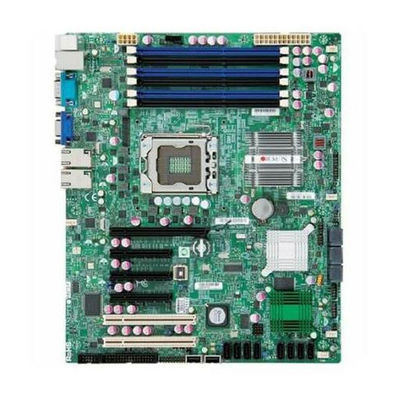
Chapter 1: Introduction Chapter 1 Introduction Overview Checklist Congratulations on purchasing your computer motherboard from an acknowledged leader in the industry. Supermicro boards are designed with the utmost attention to detail to provide you with the highest standards in quality and performance. Please check that the following items have all been included with your motherboard. - Page 10 X8ST3-F/X8STE User’s Manual X8ST3-F Image Note: All graphics shown in this manual were based upon the latest PCB Revision available at the time of publishing of the manual. The motherboard you've received may or may not look exactly the same as the graphics...
-
Page 11: Motherboard Layout
Chapter 1: Introduction Motherboard Layout FAN1 JPUSB1 SMBUS_PS1 JPW1 JPW2 DIMM3A CPU FAN DIMM3B DIMM2A DIMM2B LAN CTRL DIMM1A for IPMIl LAN DIMM1B CTRL1 Intel X58-Express North Bridge Intel Processor FAN2 Battery SPKR1 CTRL2 FAN5 JBT1 Slot6 PCI-E 2.0 X8 on X16 JWOL Intel ICH10R Slot5 PCI-E 2.0 X8... -
Page 12: Default Setting
JPL1/JPL2 #8, 9 LAN 1/2 Enable Pins 1-2 (Enabled) JPS1 SAS Enable (X8ST3-F) Pins 1-2 (Enabled) JPS2 SAS RAID Mode (X8ST3-F) On (Software RAID) JPUSB1 BP USB0/1 Wake-up Pins 1-2 (Enabled) JPUSB2 FP USB 4/5, 6/7 Wake-up Pins 1-2 (Enabled) - Page 13 #17, 18, 38, 39 Front panel accessible USB headers USB4/5, 6/7 Video Port X8ST3-F/X8STE LED Indicators Label Description Onboard Standby PWR warning LED Indicator LES1 SAS Activity (Blinking: SAS Active) (X8ST3-F only) LES2 SAS Heartbeat (Blinking: SAS Normal) (X8ST3-F only)
-
Page 14: Motherboard Features
Intel Dual-channel 82574L Gigabit (10/100/1000 Mb/s) Ethernet Controller with two Gigabit LAN ports (LAN 1 and LAN 2) • Realtek RTL8201N PHY (Dedicated LAN for X8ST3-F) • Three (3) RJ-45 backplane connectors with Link and Activity LEDs built-in I/O Devices SATA Connections •... -
Page 15: Floppy Drive
2. For the LSI 1068 Controller User's Guide, please refer to http://www. supermicro.com/support/manuals/. Integrated IPMI 2.0 (for the X8ST3-F only) • IPMI 2.0 supported by the WPCM450 Server BMC Note: For IPMI Configuration Instructions, please refer to the Embedded IPMI Configuration User's Guide available @ http://www.supermicro.com/... - Page 16 X8ST3-F/X8STE User’s Manual • Main switch override mechanism • Keyboard Wake-up from Soft-Off • USB Wake-up from Soft-Off • Wake-on-LAN • Power-on mode for AC power recovery PC Health Monitoring CPU Monitoring • Onboard voltage monitors for CPU core, Memory Voltage, Chipset Voltage, +1.8V, +3.3V, +3.3V standby, +5V, +5V, Standby, VBat and ±12V...
- Page 17 Chapter 1: Introduction Notes...
- Page 18 LPC I/O SPI EEPROM Floppy COM1 COM2 X8ST3-F/X8STE System Block Diagram Note: This is a general block diagram and may not exactly represent the features on your motherboard. See the following pages for the actual specifications of each motherboard. 1-10...
-
Page 19: Chipset Overview
Intel Xeon 5500/3500 Processor in an LGA1366 socket, the Intel X58 Express chipset, and the ICH10R. With Intel QuickPath Interconnect (QPI) technology built in, the X8ST3-F/X8STE is one of the first motherboards on the market that offers the next generation point-to-point system interconnect interface, replacing... -
Page 20: Pc Health Monitoring
X8ST3-F/X8STE User’s Manual PC Health Monitoring This section describes the PC health monitoring features of the X8ST3-F/X8STE. These features are supported by an onboard System Hardware Monitor chip. Recovery from AC Power Loss BIOS provides a setting for you to determine how the system will respond when AC power is lost and then restored to the system. -
Page 21: Bios Support For Usb Keyboard
It is even more important for processors that have high CPU clock rates of 1 GHz and faster. X8ST3-F/X8STE accommodates ATX12V standard power supplies. Although most power supplies generally meet the specifications required by the CPU, some are inadequate. A 2-Amp of current supply on a 5V Standby rail is strongly recommended. -
Page 22: Super I/O
X8ST3-F/X8STE User’s Manual It is strongly recommended that you use a high quality power supply that meets ATX12V standard power supply Specification 1.1 or above. It is also required that the 12V 8-pin power connection (JPW2) be used for adequate power supply. In areas where noisy power transmission is present, you may choose to install a line filter to shield the computer from noise. - Page 23 Chapter 1: Introduction The WPCM450 also includes the following features: • One X-Bus parallel interface for expansion I/O connections • Three ADC inputs, Analog and Digital Video outputs • Two serial for boundary scan and debug Note: For more information on IPMI configuration, please refer to the Embedded IPMI User's Guide posted on our website @ http://www.super- micro.com/support/manuals/.
- Page 24 X8ST3-F/X8STE User’s Manual Notes 1-16...
-
Page 25: Chapter 2 Installation
Chapter 2: Installation Chapter 2 Installation Static-Sensitive Devices Electrostatic-Discharge (ESD) can damage electronic com ponents. To prevent dam- age to your system board, it is important to handle it very carefully. The following measures are generally sufficient to protect your equipment from ESD. Precautions •... -
Page 26: Processor And Heatsink Installation
X8ST3-F/X8STE User's Manual Processor and Heatsink Installation When handling the processor package, avoid placing direct pressure on the label area of the fan. Notes: Always connect the power cord last and always remove it before adding, re- moving or changing any hardware components. Make sure that you install the processor into the CPU socket before you install the CPU heatsink. - Page 27 Chapter 2: Installation After removing the plastic cap, using your thumb and the index finger, hold the CPU at the north and south center edges. Align the CPU key, the semi-circle cutout, against the socket key, the notch below the gold color dot on the side of the socket.
-
Page 28: Installing A Passive Cpu Heatsink (#Snk-P0037)
X8ST3-F/X8STE User's Manual Installing a Passive CPU Heatsink (#SNK-P0037) Screw#4 Note: A heatsink bracket (BKT- 0023L) is required for a screw-type heatsink (-which is a non-pushpin Screw#1 heatsink as shown on the right.) The required heatsink bracket Screw#2 Screw#3 (BKT-0023L) can be purchased Heatsink Bracket (BKT-0023L, for from Supermicro. - Page 29 Chapter 2: Installation Finish the installation by fully tightening all four screws. Do not over-tighten to avoid possible damage to the CPU. Passive Heatsink Removal Unplug the power cord from the power supply. Using a screwdriver, loosen and remove the heatsink screws from the motherboard in the sequence as shown in the picture on the right.
-
Page 30: Mounting The Motherboard Into The Chassis
X8ST3-F/X8STE User's Manual Mounting the Motherboard into the Chassis All motherboards have standard mounting holes to fit different types of chassis. Make sure that the locations of all mounting holes for the motherboard and the chas- sis match. Although a chassis may have both plastic and metal mounting fasteners, metal ones are highly recommended because they ground the motherboard to the chassis. -
Page 31: Installing And Removing The Memory Modules
Chapter 2: Installation Installing and Removing the Memory Modules Note: Check the Supermicro web site for recommended memory modules. CAUTION Exercise extreme care when installing or removing DIMM modules to prevent any possible damage. Press down the release tabs Installing & Removing DIMMs Insert the desired number of DIMMs into the memory slots, starting with DIMM1A. -
Page 32: Memory Support
X8ST3-F/X8STE User's Manual Memory Support The X8ST3-F/X8STE supports up to 24 GB Unbuffered ECC or Non ECC DDR3 1333/1066/800 in 6 DIMM slots. DIMM Module Population Configuration For memory to work properly, follow the table below for memory installation: Memory Population (UDIMM Only Routing) - Page 33 Chapter 2: Installation Possible System Memory Allocation & Availability System Device Size Physical Memory Remaining (-Available) (4 GB Total System Memory) Firmware Hub flash memory (System BIOS) 1 MB 3.99 GB Local APIC 4 KB 3.99 GB Area Reserved for the chipset 2 MB 3.99 GB I/O APIC (4 Kbytes)
-
Page 34: Connectors/Io Ports
I/O ports. Back Panel Connectors and IO Ports Back Panel Connectors 1. Keyboard (Purple) 2. PS/2 Mouse (Green) 3. USB Port 0 4. USB Port 1 5. IPMI LAN (X8ST3-F) 6. COM 1 7. VGA 8. LAN1 9. LAN 2 2-10... -
Page 35: Atx Ps/2 Keyboard And Ps/2 Mouse Ports
Chapter 2: Installation ATX PS/2 Keyboard and PS/2 PS/2 Keyboard/Mouse Pin Mouse Ports Definitions PS2 Keyboard PS2 Mouse The ATX PS/2 keyboard and PS/2 Pin# Definition Pin# Definition mouse are located next to the Back KB Data Mouse Data Panel USB Ports 0/1 on the mother- No Connection No Connection board. -
Page 36: Universal Serial Bus (Usb)
X8ST3-F/X8STE User's Manual Universal Serial Bus (USB) Back Panel USB 0/1 Pin Definitions Two Universal Serial Bus ports (USB Pin# Definition Pin# Definition 0/1) are located on the I/O back panel. Additional six USB connections (USB USB_PN1 USB_PN0 2, USB 3, USB 4/5 and USB 6/7) are... -
Page 37: Ethernet Ports
RJ45 type cables. TD1+ Link 100 LED Notes: (Yellow, +3V3SB) TD1- Link 1000 LED 1. The IPMI Dedicated LAN (Yellow, +3V3SB) is for the X8ST3-F only. TD2+ Ground TD2- Ground 2. Please refer to the LED TD3+ Ground Indicator Section for LAN... -
Page 38: Serial Ports
X8ST3-F/X8STE User's Manual Serial Ports Serial Port Pin Definitions (COM1/COM2) A COM Port is located on the IO Pin # Definition Pin # Definition Backplane and a Serial port is lo- cated next to the Floppy Drive to provide front access. See the table on the right for pin definitions. -
Page 39: Video Connector
Chapter 2: Installation Video Connector A Video (VGA) connector is located next to the COM Port on the IO backplane. This connector is used to provide video and CRT display. Refer to the board layout below for the location. Note: If you decide use an add-on VGA card instead, you will need to disable this device using jumper JPG1. -
Page 40: Front Control Panel
X8ST3-F/X8STE User's Manual Front Control Panel JF1 contains header pins for various buttons and indicators that are normally lo- cated on a control panel at the front of the chassis. These connectors are designed specifically for use with Supermicro server chassis. See the figure below for the descriptions of the various control panel buttons and LED indicators. -
Page 41: Front Control Panel Pin Definitions
Chapter 2: Installation Front Control Panel Pin Definitions NMI Button NMI Button Pin Definitions (JF1) The non-maskable interrupt button Pin# Definition header is located on pins 19 and 20 Control of JF1. Refer to the table on the right Ground for pin definitions. Power LED Power LED Pin Definitions (JF1) The Power LED connection is located Pin#... -
Page 42: Hdd Led
X8ST3-F/X8STE User's Manual HDD LED The HDD LED connection is located HDD LED Pin Definitions (JF1) on pins 13 and 14 of JF1. Attach a Pin# Definition hard drive LED cable here to display disk activity (for any hard drive ac- HD Active tivities on the system, including Serial ATA and IDE). -
Page 43: Overheat (Oh)/Fan Fail Led
Chapter 2: Installation Overheat (OH)/Fan Fail LED OH/Fan Fail LED Pin Definitions (JF1) Connect an LED cable to the OH/ Pin# Definition Fan Fail connection on pins 7 and 8 of JF1 to provide advanced warnings Ground for chassis overheat or fan failure. OH/Fan Fail Indicator Refer to the table on the right for pin Status... -
Page 44: Reset Button
X8ST3-F/X8STE User's Manual Reset Button Reset Button The Reset Button connection is located Pin Definitions (JF1) on pins 3 and 4 of JF1. Attach it to a Pin# Definition hardware reset switch on the computer Reset case to reset the system. Refer to the Ground table on the right for pin definitions. -
Page 45: Connecting Cables
Chapter 2: Installation Connecting Cables This section provides brief descriptions and pin-out definitions for onboard headers and connectors. Be sure to use the correct cable for each header or connector. • For information on Backpanel USB and Front Panel USB ports, refer to Page 2-14. -
Page 46: Fan Headers
X8ST3-F/X8STE User's Manual Fan Headers The X8ST3-F/X8STE has five fan head- Fan Header ers (Fan1 ~ Fan5). Fans 2~5 are system Pin Definitions cooling fans. Fan 1 is used as a CPU Pin# Definition fan. These fans are 4-pin fan headers. -
Page 47: Internal Buzzer
Chapter 2: Installation Internal Buzzer Internal Buzzer Pin Definition The Internal Buzzer (SPKR1) can be Pin# Definitions used to provide audible indications for Pin 1 Pos. (+) Beep In various beep codes. See the table on Pin 2 Neg. (-) Alarm the right for pin definitions. -
Page 48: Overheat/Fan Fail Led
X8ST3-F/X8STE User's Manual Overheat/Fan Fail LED Overheat LED Pin Definitions The JOH header is used to connect Pin# Definition an LED to provide warnings of chas- 5vDC sis overheat. This LED will also blink OH Active to indicate a fan failure. Refer to the table on right for pin definitions. -
Page 49: Power Supply I 2 C Connector
Chapter 2: Installation Power Supply I C Connector PWR Supply I Pin Definitions Power Supply (I C) Connector, locat- Pin# Definition ed at SMB_PS1 on the motherboard. Clock This connector monitors the status Data of the power supply, fan and system PWR Fail temperature. -
Page 50: T-Sgpio 0/1 & 3-Sgpio 0/1 Headers
Load Ground ports are also located next to SAS Port Clock 3 on the X8ST3-F motherboard. These NC: No Connections headers are used to communicate with the enclosure management chip in the system. See the table on the right for pin definitions. -
Page 51: Wake-On-Lan
Chapter 2: Installation Wake-On-LAN Wake-On-LAN Pin Definitions The Wake-On-LAN header is located (JWOL) at JWOL on the motherboard. See the Pin# Definition table on the right for pin definitions. (You +5V Standby must also have a LAN card with a Wake- Ground On-LAN connector and cable to use this Wake-up... -
Page 52: Jumper Settings
X8ST3-F/X8STE User's Manual Jumper Settings Explanation of Jumpers To modify the operation of the mother- board, jumpers can be used to choose between optional settings. Jumpers cre- ate shorts between two pins to change the function of the connector. Pin 1 is identified with a square solder pad on the printed circuit board. -
Page 53: Cmos Clear
Chapter 2: Installation CMOS Clear JBT1 is used to clear CMOS. Instead of pins, this "jumper" consists of contact pads to prevent accidental clearing of CMOS. To clear CMOS, use a metal object such as a small screwdriver to touch both pads at the same time to short the connection. Always remove the AC power cord from the system before clearing CMOS. -
Page 54: Smb To Pci-X/Pci-E Slots Speeds
X8ST3-F/X8STE User's Manual SMB to PCI-X/PCI-E Slots Speeds SMBus to PCI-X/PCI-Exp Slots Use Jumper JI C1 to connect the System Jumper Settings Management Bus to the PCI slots, and Jumper Setting Definition Jumper JI C2, to the PCI-Exp. slots in... -
Page 55: Usb Wake-Up
Chapter 2: Installation USB Wake-Up JPUSB1 (BackPanel USB 0/1 Wake-up Enable) Use JPUSB jumpers to "wake-up" your sys- Pin# Definition tem by pressing a key on a USB keyboard or Enabled (Default) clicking the USB mouse of your system. The Disabled JPUSB jumpers are used together with the USB Wake-Up feature in the BIOS. -
Page 56: Sas Enable/Disable (X8St3-F Only)
Enabled (Default) on pins 1 and 2 to enable SAS. See the Pins 2-3 Disabled table on the right for jumper settings. SAS RAID Mode Select (X8ST3-F Only) Software RAID Jumper Settings JPS2 allows you to select the SAS RAID... -
Page 57: Bmc Ipmi Enable (X7St3-F Only)
Chapter 2: Installation BMC IPMI Enable (X7ST3-F only) JBMC1 allows the user to enable or dis- BMC IPMI Enable/Disable able BMC (Baseboard Management Con- Jumper Settings trol) Chip and the onboard IPMI connec- Settings Definition tions. This jumper is to be used together Pins 1-2 Enabled (Default) with the IPMI settings in the BIOS. -
Page 58: Onboard Indicators
In addition to LAN 1/LAN 2, an IPMI Dedi- cated LAN is also located on the IO Back- IPMI LAN IPMI LAN Link LED (Left) & Activity LED (Right) plane of the X8ST3-F. The amber LED on (X8ST3-F) Color Status Definition... -
Page 59: Sas Activity Led (X8St3-F Only)
Chapter 2: Installation SAS Activity LED (X8ST3-F Only) A SAS Activity LED is located at LES1. SAS Activity LED Indicator LED Settings When LES1 blinks, SAS is active. Refer Blinking: Green SAS is active to the table on the right for details. Also see the layout below for the LED loca- tion. -
Page 60: Onboard Power Led
X8ST3-F/X8STE User's Manual Onboard Power LED Onboard PWR LED Indicator LED Settings An Onboard Power LED is located at LE1 LED Color Definition on the motherboard. When LE1 is on, the System Off AC power cable is connected. Make sure to... -
Page 61: Serial Ata And Floppy Drive Connections
Chapter 2: Installation Serial ATA and Floppy Drive Connections Note the following conditions when connecting the Serial ATA and floppy disk drive cables: • Be sure to use the correct cable for each connector. Refer to Page 1-1 for cables that came with your shipment. -
Page 62: Floppy Connector
X8ST3-F/X8STE User's Manual Floppy Connector Floppy Drive Connector Pin Definitions The floppy connector is located near Pin# Definition Pin # Definition the PCI Slot 1 on the motherboard. Ground FDHDIN See the table on the right for pin Ground Reserved definitions. -
Page 63: Chapter 3 Troubleshooting
Chapter 3: Troubleshooting Chapter 3 Troubleshooting Troubleshooting Procedures Use the following procedures to troubleshoot your system. If you have followed all of the procedures below and still need assistance, refer to the ‘Technical Support Procedures’ and/or ‘Returning Merchandise for Service’ section(s) in this chapter. Always disconnect the AC power cord before adding, changing or installing any hardware components. -
Page 64: Memory Errors
X8ST3-F/X8STE User's Manual 2. Use the speaker to determine if any beep codes exist. (Refer to Appendix A for details on beep codes.) 3. Remove all memory modules and turn on the system. (If the alarm is on, check the specs of memory modules, reset the memory or try a different one.) Memory Errors 1. -
Page 65: Frequently Asked Questions
Frequently Asked Questions Question: What type of memory does my motherboard support? Answer: The X8ST3-F/X8STE supports up to 24 GB of unbuffered ECC or non-ECC DDR3 (1.5V) 1333/1066/800 MHz, two-way interleaved or non- interleaved SDRAM. See Section 2-4 for details on installing memory. - Page 66 X8ST3-F/X8STE User's Manual BIOS warning message and the information on how to update your BIOS on our web site. Select your motherboard model and download the BIOS ROM file to your computer. Also, check the current BIOS revision and make sure that it is newer than your BIOS before downloading.
-
Page 67: Returning Merchandise For Service
Chapter 3: Troubleshooting Answer: No, the PCI-Ex16 slot is not only for graphic cards. It may be used for PCI-E storage, LAN, and other peripherals. Question: Does X8 series motherboards come with a screw type CPU heat sink bracket? Answer: No, it does not come with a bracket for a screw-type heat sink. Cus- tomers have to purchase it separately. - Page 68 X8ST3-F/X8STE User's Manual Notes...
-
Page 69: Chapter 4 Bios
BIOS Introduction This chapter describes the AMI BIOS Setup Utility for the X8ST3-F/X8STE. The AMI ROM BIOS is stored in a Flash EEPROM and can be easily updated. This chapter describes the basic navigation of the AMI BIOS Setup Utility setup screens. -
Page 70: How To Start The Setup Utility
X8ST3-F/X8STE User’s Manual How to Start the Setup Utility Normally, the only visible Power-On Self-Test (POST) routine is the memory test. As the memory is being tested, press the <Delete> key to enter the main menu of the AMI BIOS Setup Utility. From the main menu, you can access the other setup screens. - Page 71 <Tab> key or the arrow keys to move between fields. The date must be entered in Day MM/DD/YY format. The time is entered in HH:MM:SS format. (Note: The time is in the 24-hour format. For example, 5:30 P.M. appears as 17:30:00.) Supermicro X8ST3-F/X8STE Version Build Date...
-
Page 72: 4-3 Advanced Setup Configurations
X8ST3-F/X8STE User’s Manual 4-3 Advanced Setup Configurations Use the arrow keys to select Boot Setup and hit <Enter> to access the submenu items: BOOT Feature Quick Boot If Enabled, this option will skip certain tests during POST to reduce the time needed for system boot. - Page 73 Chapter 4: AMI BIOS Wait For 'F1' If Error This forces the system to wait until the 'F1' key is pressed if an error occurs. The options are Disabled and Enabled. Hit 'Del' Message Display This feature displays "Press DEL to run Setup" during POST. The options are Enabled and Disabled.
- Page 74 X8ST3-F/X8STE User’s Manual ting. Select Auto for the BIOS to automatically select the CPU multiplier setting for your system. The options are Auto and Manual. Clock Spread Spectrum Select Enable to use the feature of Clock Spectrum, which will allow the BIOS to monitor and attempt to reduce the level of Electromagnetic Interference caused by the components whenever needed.
- Page 75 Chapter 4: AMI BIOS Intel AES-NI (When supported by the CPU) Intel® AES instructions are a new set of instructions available beginning with the the all new 2010 Intel® Core™ processor family based on the 32nm Intel® microarchitecture. These instructions enable fast and secure data encryption and decryption, using the Advanced Encryption Standard (AES).
-
Page 76: Advanced Chipset Control
X8ST3-F/X8STE User’s Manual C3 Auto Demotion When enabled, the CPU will conditionally demote C6 or C7 requests to C3 based on un-core auto-demote information. The options are Disabled and Enabled. ACPI T State This feature Enables the ACPI throttling support for the processor to save power. - Page 77 Chapter 4: AMI BIOS L0s is intended as a power saving state. It allows a link to quickly enter and recover form a power saving state without going through recovery. L1 is a power saving state that allows an additional power saving over L0s, but with additional resume (wake-up) latency.
- Page 78 X8ST3-F/X8STE User’s Manual Throttling - Closed Loop Throttling improves reliability and reduces power in the processor by au- tomatic voltage control during processor idle states. Available options are Disabled and Enabled. Intel VT-d Select Enabled to enable Intel's Virtualization Technology support for Direct I/O VT-d by reporting the I/O device assignments to VMM through the DMAR ACPI Tables.
- Page 79 Chapter 4: AMI BIOS Legacy USB Support Select Enabled to use Legacy USB devices. If this item is set to Auto, Legacy USB support will be automatically enabled if a legacy USB device is installed on the motherboard, and vise versa. The settings are Disabled, Enabled and Auto. IDE / Floppy Configuration ...
- Page 80 X8ST3-F/X8STE User’s Manual activate the following submenu screen for detailed options of these items. Set the correct configurations accordingly. The items included in the submenu are: Type Select the type of device connected to the system. The options are Not Installed, Auto, CD/DVD and ARMD.
- Page 81 Chapter 4: AMI BIOS DMA Mode Select Auto to allow the BIOS to automatically detect IDE DMA mode when the IDE disk drive support cannot be determined. Select SWDMA0 to allow the BIOS to use Single Word DMA mode 0. It has a data transfer rate of 2.1 MB/s.
- Page 82 X8ST3-F/X8STE User’s Manual the S.M.A.R.T. Select Enabled to allow the AMI BIOS to use the S.M.A.R.T. to support hard drive disk. The options are Disabled, Enabled, and Auto. 32-Bit Data Transfer Select Enable to enable the function of 32-bit IDE data transfer. The options are Enabled and Disabled.
- Page 83 This feature is to enable LAN OPROM for PXE. This is to boot computers using a network interface. The options are Disabled and Enabled. Load SAS Option ROM (X8ST3-F Only) This feature is to load the Serial Attached SCSI (SAS) option ROM, if available.
-
Page 84: Hardware Health Configuration
X8ST3-F/X8STE User’s Manual ditional option, Onboard IPMI is featured on the X8ST3-F motherboard only, and becomes the default. Serial Port Mode This feature allows the user to set the serial port mode for Console Redirection. The options are 115200 8, n 1; 57600 8, n, 1; 38400 8, n, 1; 19200 8, n, 1; and 9600 8, n, 1. - Page 85 Chapter 4: AMI BIOS Warning: Any temperature that exceeds the CPU threshold temperature predefined by the CPU manufacturer may result in CPU overheat or system instability. When the CPU temperature reaches this predefined threshold, the CPU and system cooling fans will run at full speed. The options are: •...
- Page 86 X8ST3-F/X8STE User’s Manual speed to bring the CPU temperature down. If the CPU temperature still increases even with the CPU fan running at full speed, the system buzzer will activate and the Overheat LED will turn on. The Early Alarm – the Overheat LED and system buzzer will be activated exactly when the High level is reached.
- Page 87 Chapter 4: AMI BIOS system cooling. Select Full Speed to allow the onboard fans to run at full speed (of 100% Pulse Width Modulation Duty Cycle) for maximum cooling. The Full Speed setting is recommended for special system configuration or debugging. Select Performance for the onboard fans to run at 70% of the Initial PWM Cycle for better system cooling.
- Page 88 X8ST3-F/X8STE User’s Manual APIC ACPI SCI IRQ When this item is set to Enabled, APIC ACPI SCI IRQ is supported by the system. The options are Enabled and Disabled. Headless Mode This feature is used to enable system to function without a keyboard, monitor or mouse attached The options are Enabled and Disabled.
- Page 89 Chapter 4: AMI BIOS Channel Number Status - This feature returns the channel status for the Channel Number selected above: "Channel Number is OK" or "Wrong Channel Number". IP Address Source - This feature selects whether the IP address, Subnet Mask and Gateway Address are automatically assigned by the network's DHCP server (Dynamic Host and Configuration Protocol) or manually entered by the user (Static).
- Page 90 X8ST3-F/X8STE User’s Manual Clear event log This option clears the Event Log memory of all messages. The options are OK and Cancel. PCIE Error Log Use this option to enable logging of errors encountered in the system's PCIe bus. The options are Yes and No.
-
Page 91: Security Settings
Chapter 4: AMI BIOS Security Settings The AMI BIOS provides a Supervisor and a User password. If you use both pass- words, the Supervisor password must be set first. Supervisor Password This item indicates if a supervisor password has been entered for the system. Clear means such a password has not been used and Set means a supervisor password has been entered for the system. -
Page 92: 4-5 Boot Configuration
X8ST3-F/X8STE User’s Manual Clear User Password (Available only if User Password has been set) Password Check Available options are Setup and Always. Boot Sector Virus Protection When Enabled, the AMI BOIS displays a warning when any program (or virus) is- sues a Disk Format command or attempts to write to the boot sector of the hard disk drive. -
Page 93: Exit Options
Chapter 4: AMI BIOS Hard Disk Drives This feature allows the user to specify the boot sequence from all available hard disk drives. The settings are Disabled and a list of all hard disk drives that have been detected (i.e., 1st Drive, 2nd Drive, 3rd Drive, etc). Removable Drives This feature allows the user to specify the boot sequence from available Removable Drives. - Page 94 X8ST3-F/X8STE User’s Manual figuration parameters can take effect. Select Save Changes and Exit from the Exit menu and press <Enter>. Discard Changes and Exit Select this option to quit the BIOS Setup without making any permanent changes to the system configuration, and reboot the computer. Select Discard Changes and Exit from the Exit menu and press <Enter>.
-
Page 95: Appendix A Post Error Beep Codes
Appendix A: POST Error Beep Codes Appendix A POST Error Beep Codes This section lists POST (Power On Self Test) error beep codes for the AMI BIOS. POST error beep codes are divided into two categories: recoverable and terminal. This section lists Beep Codes for recoverable POST errors. Recoverable POST Error Beep Codes When a recoverable type of error occurs during POST, BIOS will display a POST code that describes the problem. - Page 96 X8ST3-F/X8STE User's Manual Notes...
-
Page 97: Appendix B Installing The Windows Os
Appendix B: Installing the Windows OS Appendix B Installing the Windows OS After all hardware components have been installed, you must first configure Intel South Bridge RAID Settings before you install the Windows OS and other software drivers. To configure RAID settings, please refer to RAID Configuration User Guides posted on our website at www.supermicro.com/support/manuals. -
Page 98: Installing The Windows Os For Systems Without Raid Functions
X8ST3-F/X8STE User's Manual Guide Installing the Windows OS for Systems without RAID Functions Insert Microsoft's Windows XP/2003 Setup CD in the CD Driver, and the system will start booting up from CD. Press the <F6> key when the message-" Press F6 if you need to install a third party SCSI or RAID driver" displays. When the Windows XP/2003 Setup screen appears, press "S" to specify additional device(s). -
Page 99: Appendix C Software Installation Instructions
Appendix C: Software Installation Instructions Appendix C Software Installation Instructions C-1 Installing Drivers After you've installed the Windows Operating System, a screen as shown below will appear. You are ready to install software programs and drivers that have not yet been installed. To install these software programs and drivers, click the icons to the right of these items. -
Page 100: Configuring Supero Doctor Iii
X8ST3-F/X8STE User's Manual C-2 Configuring Supero Doctor III The Supero Doctor III program is a Web-base management tool that supports remote management capability. It includes Remote and Local Management tools. The local management is called the SD III Client. The Supero Doctor III program included on the CDROM that came with your motherboard allows you to monitor the environment and operations of your system. - Page 101 Appendix C: Software Installation Instructions Supero Doctor III Interface Display Screen-II (Remote Control) Note: SD III Software Revision 1.0 can be downloaded from our Web site at: ftp://ftp.supermicro.com/utility/Supero_Doctor_III/. You can also download SDIII User's Guide at: http://www.supermicro.com/PRODUCT/ Manuals/SDIII/UserGuide.pdf. For Linux, we will still recommend that you use Supero Doctor II.
- Page 102 X8ST3-F/X8STE User's Manual Notes...
-
Page 103: Appendix D - Bios Recovery
Appendix D: BIOS Recovery Appendix D - BIOS Recovery The recovery procedure described in this section is to be used only when advised by your Supermicro Technical Support representative, or in cases of emergencies where the system no longer can boot due to a corrupted BIOS. DO NOT re-program (re-flash) the BIOS if your system is running properly. -
Page 104: Recovery Process From An Ide/Sata Atapi Disc Drive
X8ST3-F/X8STE User’s Manual When the Boot Sector Recovery Process is complete, the system will reboot automatically and you will see a checksum error on your screen. Part 2 - BIOS Reprogramming (Re-Flashing) After completing the Boot Sector Recovery Process, you will need to reprogram (“re-flash”) the proper BIOS binary file again into the BIOS ROM in order to have... - Page 105 (Disclaimer Continued) The products sold by Supermicro are not intended for and will not be used in life support systems, medical equipment, nuclear facilities or systems, aircraft, aircraft devices, aircraft/emergency communication devices or other critical systems whose failure to perform be reasonably expected to result in significant injury or loss of life or catastrophic property damage.
Need help?
Do you have a question about the Supero X8ST3-F and is the answer not in the manual?
Questions and answers