Table of Contents
Advertisement
Advertisement
Table of Contents

Related Manuals for First Alert SmartBridge DVRAD0405


Summary of Contents for First Alert SmartBridge DVRAD0405
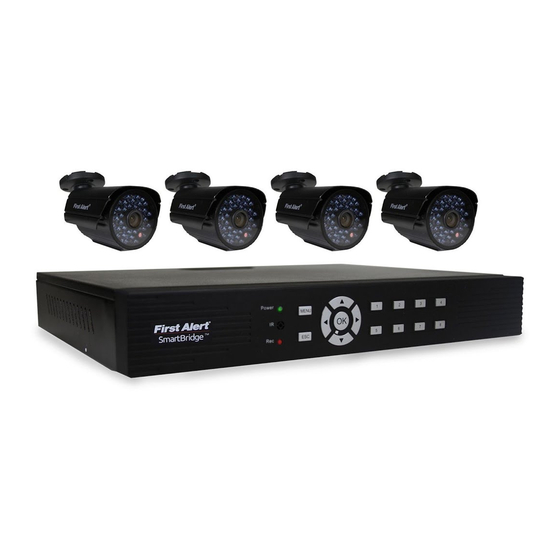
- Page 1 USER’S MANUAL Model DVRAD0405/DVRAD0805/DVRAD0810/DVRAD1610/DVRAD1620...
-
Page 2: Introduction
© 2013 BRK Brands, Inc. All rights reserved. Distributed by BRK Brands, Inc., Aurora, Illinois 60504. BRK Brands, Inc. is a subsidiary of Jarden Corporation (NYSE: JAH). First Alert® and SmartBridge™ are registered trademarks of the First Alert Trust. Due to continuing product develop- ment, the product inside the packaging may look slightly different than the one on the package. - Page 3 INTRODUCTION KEY PRODUCT FEATURES Main Description Four, eight or sixteen channel H.264 digital video recorder with Internet remote surveillance, motion detection, PTZ and alarm control suitable for applications such as high-end residential - new or remodel, light commercial, small business/retail, small warehouse or small grocery Product Features •...
-
Page 4: Table Of Contents
INTRODUCTION TABLE OF CONTENTS ection eScription Introduction Safety Product Overview What is in the Box DVR Controls Front Panel Back Panel Remote Control Mouse and Virtual Keypad Camera Power Connections Connecting Devices Initial Setup - System Operation System Start Up Power On/Off Setup Wizard Setup Wizard System Setup Menu... -
Page 5: Introduction
INTRODUCTION TABLE OF CONTENTS ection eScription Remote Access Network Setup 40-42 External Recording External Playback Settings Advanced Setting Pan Tilt Zoom Setting Up Groups Remote Configuration Camera Settings Appendix Hard Drive Removal and Installation Specifications FAQ’s (Frequently Asked Questions) Troubleshooting Warranty Page 5... -
Page 6: Safety
FCC approval of this device. The phone number listed below is for FCC related questions only and not intended for questions regarding the connection or operation for this device. FCC Declaration of Conformity for devices with the FCC logo. Responsible Party: First Alert / BRK Brands, Inc., 3901 Liberty Street Rd., Aurora, IL. 60504- 8122 Telephone: (630) 851 - 7330. -
Page 7: Product Overview
© 2012 BRK Brands, Inc. All rights reserved. Distributed by BRK Brands, Inc., Aurora, Illinois 60504. BRK Brands, Inc. is a subsidiary of Jarden Corporation (NYSE: JAH). First Alert® is a registered trademark of the First Alert Trust. Due to continuing product development, the product inside the packaging may look slightly different than the one on the package. -
Page 8: Dvr Controls
PRODUCT OVERVIEW DVR CONTROLS Front Panel 4 Channel DVR 8 Channel DVR 16 Channel DVR unction ontrol eScription (1) IR remote receiver Direct remote towards this position when using DVR Power indicator light A green light indicates power is on Record indicator light A green flashing light indicates recording Buttons 1-4(8)(16) -
Page 9: Back Panel
PRODUCT OVERVIEW DVR CONTROLS Back Panel 4 Channel DVR 8 Channel DVR 16 Channel DVR unction eScription Alarm 4 alarm inputs; 1 alarm output VGA Output For connecting to VGA monitor HDMI Output For connecting to HDMI monitor USB/Mouse Use Lower USB port for mouse connection; Use Upper USB port for USB flashdrive or backup For connecting RJ45 ethernet cable to PC or router RS485 For connecting PTZ cameras... -
Page 10: Remote Control
PRODUCT OVERVIEW REMOTE CONTROL Remote Control Remote Control Operation The remote control is the secondary input device for navigating the system’s interface. In device operation, the MENU key has the same function as “left click” of the mouse. unction eScription Power Click power for about 3-5 seconds to shut down the DVR. -
Page 11: Mouse And Virtual Keypad
PRODUCT OVERVIEW MOUSE AND VIRTUAL KEYPAD Mouse Controls Mouse Operation with this DVR The mouse is the primary input device for navigating system menus. NOTE: Unless otherwise noted, all system functions described in this manual are achieved through mouse input. To use a mouse with the system: Connect a USB mouse to the USB MOUSE port on back panel of the system. -
Page 12: Camera Power Connections
Video to DVR Channels 1-8 Splitter Cable AV Cable: BNC/DC Power Power to Camera (1 per Camera) DC Converter - 12V Power from 120V Video to Camera Use First Alert Power Supply Only Use First Alert Cameras Only Page 12... -
Page 13: Initial Setup System Operation
INITIAL SETUP SYSTEM OPERATION Powering your DVR and Cameras The power supply included with the DVR is rated for 5 amps. Normally, this is enough to power both the DVR and supplied cameras. However, using aftermarket cameras or a larger number of cameras may sur- pass the capability of the power supply, causing the systerm to shut down. -
Page 14: Setup Wizard Setup Wizard
INITIAL SETUP SETUP WIZARD Setup Wizard Quick Startup After the initial system power up, the system will ask for a login. The default user is “abc” and there is no password. Simply click login, after which the Setup Wizard will start. Clicking on “Next”... -
Page 15: Setup Wizard
INITIAL SETUP SETUP WIZARD • Resolution (Main) Choose between “None(Camera Default)”, “CIF(352x288)” or “D1(720x480)” resolutions • kbps (Main) Choose transmission rate for camera channel NOTE: A higher kbps will result in larger video files • Resolution (Minor) Choose between “None(Main Setting Default)”, “QCIF(176×144)”... -
Page 16: System Setup Menu
SYSTEM SETUP GENERAL MENU System Setup General Menu Path: System Setup>General After the system powers up, and the user is logged in, the Right Click Menu can be accessed. To access basic System Settings, select the first option, “System Setup.” To open the System Setup Menu: Right-click anywhere on-screen to open the Quick Access Menu and select System Setup (mouse only), or press the... - Page 17 SYSTEM SETUP GENERAL MENU General Menu (Continued) Path: System Setup>General • Date Format Set the date format according to your local preference • Set Date Enter the current date here • Auto Synchronize Time • Enable DST Adjusts and sets system time to Set time to adjust •...
-
Page 18: Channel
SYSTEM SETUP CHANNEL MENU • View Setting This tab adjusts certain channel appearance options • Channel The channel number according to view arrangement • Channel Name The channel name can be changed here, Channel Menu i.e., CH01 will Path: System be displayed as Setup>Channel Front Hall... -
Page 19: Channel
SYSTEM SETUP CHANNEL MENU Channel Menu (Continued) Path: System Setup>Channel • Resolution (Main) Choose between “None(Camera Default)”, “CIF(352x288)” or “D1(720x480)” resolutions • kbps (Main) Choose transmission rate for camera channel NOTE: A higher kbps will result in larger video files •... -
Page 20: Network
SYSTEM SETUP NETWORK MENU Network Menu Path: System Setup>Network Using the Network menu, settings for the DVR’s connection to a network and the internet can be changed and adjusted. • IP The DVR’s IP address can be manually set here •... -
Page 21: Network
SYSTEM SETUP NETWORK MENU Network Menu (Continued) Path: System Setup>Network • Service • WebCC Sets parameters to use a Closed Circuit platform over a Toggle Web Closed network connection Circuit capability over the network • Port Set an open port for WebCC to access on the network •... - Page 22 SYSTEM SETUP ALARM MENU Alarm Menu Path: System Setup>Alarm Settings for different alarm parameters can be set from the Alarm menu, including how and when an alarm is triggered. Use the Alarm In feature to configure alarm settings. NOTE: External alarm devices must be connected to the alarm block on the rear panel of the DVR in order to use the I/O (input/ •...
-
Page 23: Alarm Menu
SYSTEM SETUP ALARM MENU Alarm Menu (Continued) Path: System Setup>Alarm • Channel Indicates the channel • Keep Alarm How long the alarm will be active • Enable before being cancelled Sets the alarm settings for a • Turn on Buzzer channel to on or off Activate DVR alarm buzzer •... - Page 24 SYSTEM SETUP ALARM MENU Alarm Menu (Continued) Path: System Setup>Alarm • End Time Indicates time to end settings. NOTE: 24 hour clock • Channel • Enable • Start Time Indicates the Sets the Indicates time to channel alarm begin settings. settings NOTE: 24 hour clock for a...
-
Page 25: Alarm
SYSTEM SETUP ALARM MENU Alarm Menu • Inbound Setting (Continued) Select settings for DVR to Path: System Setup>Alarm receive email • Inbound Site Enter the site for the inbound mailbox • Modify Adjust Inbound email settings • E-Mail Adjust settings for E-Mail alarms, and destination email address and settings •... - Page 26 SYSTEM SETUP SYSTEM MENU System Menu Path: System Setup>System Access system logs, system maintenance options and information on the DVR • Type Filter log display according to type of event • Detail Detailed information of a selected log event • Backup Record log file to an external USB drive •...
-
Page 27: System
SYSTEM SETUP SYSTEM MENU System Menu (Continued) Path: System Setup>System • maint • Scheduled Restart Settings and options to update DVR Toggle if/when the DVR will do an automatic reboot. NOTE: time is on 24 hour clock • Update Type Select where data is pulled from to update the DVR •... -
Page 28: Device
SYSTEM SETUP DEVICE MENU Device Menu Path: System Setup>Device Access device options for hardware connected to the • Device Storage device type and name • Used Amount of data on device • Capacity Amount of storage capacity of device • Status Current status of the Hard Drive •... - Page 29 SYSTEM SETUP DEVICE MENU System Menu (Continued) Path: System Setup>System • Channel Select the channel that has a PTZ camera • Address Address of the PTZ camera • Protocol Select operating code for PTZ camera • BR Baud rate • Left Right Swap Mirror joystick left/right movement •...
-
Page 30: Basic Operation
VIEW LAYOUT VIDEO OPERATION View Layout The number of channels displayed can be controlled from this menu. One camera channel can be selected to fill the whole display, or a number of different channels can subdivide the display. • View 1 Select which Channel to fill entire display •... -
Page 31: Video Adjust
VIDEO ADJUST VIDEO OPERATION Video Adjust Each camera channel can be adjusted individually • Lightness for brightness, contrast and saturation. To adjust: Adjust the lightness of 1. Channel: Select the proper channel for the channel adjustment using the Channel drop down. between 0 and 2. -
Page 32: Ptz (Pan Tilt Zoom) Camera
VIDEO OPERATION Pan/Tilt/Zoom (PTZ) Setup: NOTE: Consult the instruction manual of your PTZ camera for complete information about your camera, including protocol, baud rate and parity settings before PTZ Inputs Configuration beginning setup. Enter these settings in the DVR. – –... -
Page 33: Clients
CLIENTS NETWORK OPERATION will move while being controlled Clients manually. Certain PTZ camera will use only part of the range. • Zoom: “+” zooms in and “-” zooms This menu will display a current list of network users logged onto the •... -
Page 34: Snapshot
SNAPSHOT & PHOTO RECORDING OPERATION Snapshot Snapshot is used to take a photo of a particular channel • Taking a Snapshot Using the mouse, left-click on a channel display to take and save a snapshot • Exiting Snapshot Using the mouse, right- click to exit snapshot Photos Photo is used to review photos... -
Page 35: Record Setup
RECORD SETUP RECORDING OPERATION Record Setup Record Setup is used to set scheduled or manual recording • Channel List of channels • Manual Select to begin manual recording of a channel • Scheduled The “Set” Button will launch a new sub menu to set recording schedules when Type is changed to... - Page 36 RECORD SETUP RECORDING OPERATION Scheduling Recording (cont.) Scheduled will appear when the “Scheduled” type is selected from the Record Type menu for each channel (See page • Set Will launch a menu to adjust recording types and settings for each day of the week •...
-
Page 37: Record Setup
RECORD SETUP RECORDING OPERATION Record Setup Use the Scheduled submenu, accessed from Record Setup (See page 36), to set various recording styles and times for each channel. Use the mouse to click and drag a time or set the time by using the on-screen keyboard. Use the mouse to click and drag a time or set the... -
Page 38: Playback
PLAYBACK RECORDING OPERATION Playback Recorded video is accessed through the Search Recording screen. To access the recordings, right click the mouse to access the quick menu drop down. Select PLAYBACK. The SEARCH RECORDING screen will appear on screen. To Find & Play Recordings: 1. -
Page 39: Clear Alarm
CLEAR ALARM & SHUTDOWN SYSTEM OPERATION Clear Alarm Clears and cancels current channel alarms • Current Cancels current alarm on a channel • Clear All Clears all alarms on all channels Shutdown The system provides the ability with a controlled shut down, through a power down or with a Restart. -
Page 40: Remote Access
REMOTE ACCESS NETWORK SETUP Network Setup for Remote Access Network Setup for Remote Access Your Smartbridge system is capable of connecting to a local area network (LAN) to view remotely, without the use of port forwarding. Please follow the steps below. Right click and select “System Setup.”... - Page 41 REMOTE ACCESS NETWORK SETUP The connect tab is for connecting to one SmartBridge DVR only. Use the advanced Tab when connecting to multiple Smartbridge DVR’s at once. (Group). See adding groups section. • Click Port to enter the port settings. This is to assign a router port that is open.
- Page 42 REMOTE ACCESS NETWORK SETUP Press this button to connect all cameras connected to the Auto ID system. Also, Right click on a camera source screen and select connect. Press this button to disconnect all cameras connected to the Auto ID system. Also, Right click on a camera source screen and select disconnect.
-
Page 43: External Recording
REMOTE ACCESS NETWORK SETUP External Recording You are able to record using the remote software simultaneously to recording on the Smartbridge DVR system. In order to record using the Smartbridge remote software, you will need an 80 GB minimum external hard drive formatted to FAT32. Plug an external hard drive into your computer. -
Page 44: External Playback
REMOTE ACCESS EXTERNAL PLAYBACK External Playback Select Playback external to play back recorded files. All files available on the External hard drive can be played back on the Smartbridge Software. Select the channel from the dropdown of the channel you would like to playback. Double click the file you would like to playback. Shows sixteen channels in Opens a saved .sv5 file No Function... -
Page 45: Settings
REMOTE ACCESS SETTINGS Settings Select to adjust specific settings for your Smartbridge DVR. (See recording external for Storage Tab information) Select the Advanced Tab. Check the Place system always on top box to place the Smartbridge on top of all other software within the operating system. Check the Disabled Ctrl-Alt-Del when system is locked box to disable the use of Ctrl-Alt- Del when you lock the system. -
Page 46: Advanced Setting
REMOTE ACCESS ADVANCED SETTINGS Advanced Settings Select to open the advanced settings options for your Smartbridge DVR • Switch User (Feature enabled in advanced mode only): Switches between users (see setting up groups) • TV Mode: Select TV mode to place all connected channels to share the full screen. -
Page 47: Pan Tilt Zoom
REMOTE ACCESS PAN TILT ZOOM Pan Tilt Zoom If you have pan tilt zoom cameras installed, you are able to control the pan tilt zoom cameras remotely with the Smartbridge Software. Press to move PTZ camera up Press to move PTZ camera left Press to move PTZ camera down Press to move PTZ camera right Iris... -
Page 48: Setting Up Groups
REMOTE ACCESS DVR GROUPS Setting Up Groups With the Smartbridge Software, you are able to set up multiple DVR’s for remote viewing called groups. This is beneficial if you have multiple locations requiring surveillance. To set up a group, you need to have more than one Smartbridge DVR connected to a network. Select the Advanced Tab To add a group, Select settings Default username is abc and default password is 123... -
Page 49: Remote Configuration
REMOTE ACCESS CAMERA SETTINGS Remote Configuration With the Smartbridge software, you are able to configure camera settings remotely. To do this, right click on any camera source that has a camera connected and select set remotely. (Note, for this feature to be enabled, you must select the enable devices management box in settings – Advanced. Web service - currently not function Mobile service - to enable mobile browsing Port - this is the web port which should always be at 80... - Page 50 REMOTE ACCESS CAMERA SETTINGS Channel –select channel of the PTZ Minor FPS - Choose the frames per Ch name – give the channel number a name seconded – higher the better Main – quality of camera - CIF or D1 on 4/8 channel Standard/Net Mode on 16 channel Address: Address of the PTZ camera Minor- low quality of camera-...
-
Page 51: Appendix
APPENDIX HARD DRIVE Hard Drive Removal and Installation HDD Installation To replace the hard drive in the DVR: CAUTION: TO REDUCE THE RISK OF ELECTRIC SHOCK. UNPLUG ALL POWER SOURCES, INCLUDING CAMERAS FROM THE DVR BEFORE REMOVING COVER. FAILURE TO DO SO CAN RESULT IN DAMAGE TO THE DVR OR ITS COMPONENTS AS WELL AS INJURY OR DEATH Remove screws securing the cover of the DVR and remove cover. -
Page 52: Specifications
APPENDIX SPECIFICATIONS Technical Specifications Item Device Parameter Specification Language English/ Spanish/ French System 16 Bit Graphic menu (OSD Menu) Password User password, Administrator password Video in 4/8/16 channel composite video input 1.0Vp-p, impedance 75Ω, BNC Video out 1 VGA, 1 BNC (CVBS), 1 HDMI Video Video display 4/8/16 channel: 1/4/8/9... -
Page 53: Faq's (Frequently Asked Questions)
APPENDIX FAQ’s If your problem is not listed below, please call our toll-free Question: Why is there no audio sound when monitoring? number for more support. Tech Services: 800-323-9005. Answer: • Check sound box or speaker functions. Question: Why does DVR not work after Also check possible short circuit. -
Page 54: Troubleshooting
APPENDIX TROUBLESHOOTING Troubleshooting Error Possible Cause Solutions • Confirm that all cables are connected correctly • Confirm that the power adapter is securely connected to the back Cable from power adapter is loose or is unplugged of the unit • Confirm that the system is powered on (LED indicators on the System is not receiving front should be ON) power or is not powering up... -
Page 55: Warranty
PRODUCT LIMITED WARRANTY BRK Brands, Inc., (“BRK”) the maker of First Alert® brand products warrants that for a period of one year from the date of purchase (the “Warranty Period”), this product will be free from defects in material and workmanship. BRK, at its sole option, will repair or replace this product or any component of the product found to be defective during the Warranty Period. - Page 56 ©2014 BRK Brands, Inc. a Jarden Corporation Company (NYSE:JAH) 3901 Liberty Street Road, Aurora, IL 60504-8122 Phone: 630-851-7330 Tech Services: 800-323-9005 www.FirstAlert.com / www.brkelectronics.com M08-0490-000...
Need help?
Do you have a question about the SmartBridge DVRAD0405 and is the answer not in the manual?
Questions and answers