Table of Contents
Advertisement
IMPORTANT SERVICE NOTES (FOR U.S.A. ONLY)....................................................................................................... 2
SPECIFICATIONS ............................................................................................................................................................. 2
NAMES OF PARTS ........................................................................................................................................................... 3
QUICK GUIDE ................................................................................................................................................................... 5
DISASSEMBLY .................................................................................................................................................................. 6
REMOVING AND REINSTALLING THE MAIN PARTS ..................................................................................................... 8
ADJUSTMENT ................................................................................................................................................................... 9
NOTES ON SCHEMATIC DIAGRAM .............................................................................................................................. 11
TYPE OF TRANSISTER .................................................................................................................................................. 11
WAVEFORMS OF CD CIRCUIT ...................................................................................................................................... 12
BLOCK DIAGRAM ........................................................................................................................................................... 13
SCHEMATIC DIAGRAM / WIRING SIDE OF P.W.BOARD .............................................................................................. 16
VOLTAGE ........................................................................................................................................................................ 28
TROUBLESHOOTING ..................................................................................................................................................... 29
FUNCTION TABLE OF IC ................................................................................................................................................ 33
LCD SEGMENT ................................................................................................................................................................ 38
SERVICE MANUAL
CONTENTS
SHARP CORPORATION
- 1 -
CD-C602
CP-C602
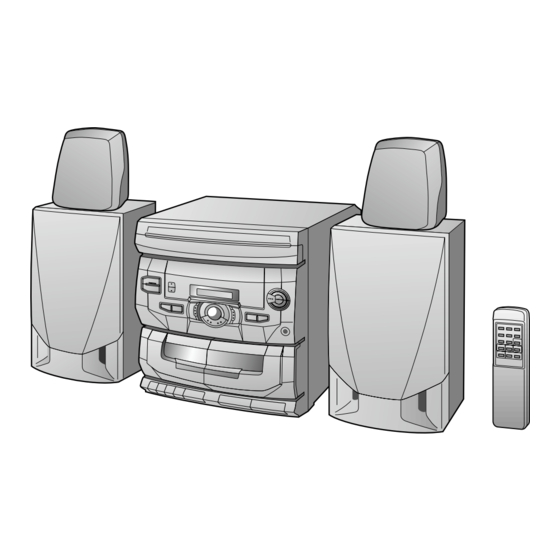
CD-C602 mini component system consisting of
CD-C602 mini component system, CP-C602 and rear
(GBOXS0020AWM1) speaker system.
• In the interests of user-safety the set should be restored to its
original condition and only parts identical to those specified be
used.
This document has been published to be used
for after sales service only.
The contents are subject to change without notice.
CD-C602,CP-C602
No. S1903CDC602//
Page
Advertisement
Table of Contents

Related Manuals for Sharp CD-C602


Summary of Contents for Sharp CD-C602
-
Page 1: Table Of Contents
CD-C602 CP-C602 CD-C602 mini component system consisting of CD-C602 mini component system, CP-C602 and rear (GBOXS0020AWM1) speaker system. • In the interests of user-safety the set should be restored to its original condition and only parts identical to those specified be used. -
Page 2: Important Service Notes (For U.s.a. Only)
CD-C602,CP-C602 FOR A COMPLETE DESCRIPTION OF THE OPERATION OF THIS UNIT, PLEASE REFER TO THE OPERATION MANUAL. IMPORTANT SERVICE NOTES (FOR U.S.A. ONLY) BEFORE RETURNING THE AUDIO PRODUCT (Fire & Shock Hazard) Before returning the audio product to the user, perform the following safety checks. -
Page 3: Names Of Parts
CD-C602,CP-C602 NAMES OF PARTS CD-C602 Front panel Disc Tray CD Play Indicator: Disc Number Indicators FM Stereo Mode Indicator: ST Extra Bass Indicator: X-BASS Memory Indicator X-BASS MEMORY CD Pause Indicator: CD Repeat Indicator: FM Stereo Indicator: Power Button Memory Button... - Page 4 CD-C602,CP-C602 Speaker section GBOXS0020AWM1 Rear speaker Woofer Speaker Wire CP-C602 Front speaker Woofer Bass Reflex Duct Speaker Wire CD-C602 Remote control Remote Control Transmitter LED Stop Button: (CD) Track Down/Review Button: (TUNER) Preset Down Button: (CD) Track Up/Cue Button: (TUNER) Preset Up Button:...
-
Page 5: Quick Guide
CD-C602,CP-C602 QUICK GUIDE MINI COMPONENT SYSTEM Quick-Guide Guía rápida CD-C602 Turning the power on and off Preparation for use Remote control Conexión y desconexión de la Preparación para su uso Control remoto alimentación Remote Sensor (Left) (Right) Sensor remote (Izquierdo) -
Page 6: Disassembly
CD-C602,CP-C602 DISASSEMBLY CD-C602 Caution on Disassembly Follow the below-mentioned notes when disassembling the unit and reassembling it, to keep it safe and ensure Top Cabinet excellent performance: (A1)x2 Hook 1. Take cassette tape and compact disc out of the unit. - Page 7 CD-C602,CP-C602 Display PWB Shift Lever (K1) x4 (E1)x8 Hook ø3x10mm ø3 x12mm (E2)x2 PWB Spacer (L1) x1 Front (E1)x1 ø2.6 x10mm Panel ø3x10mm CD Changer (E3)x5 Mechanism Spacer CD Player Base CD Mechanism (E1)x1 Be careful when installing the CD changer mechanism.
-
Page 8: Removing And Reinstalling The Main Parts
CD-C602,CP-C602 REMOVING AND REINSTALLING THE MAIN PARTS CD MECHANISM SECTION Perform steps 1, 2, 3, and 8 ~ 11 of the disassembly method to remove the CD mechanism. How to remove the turntable up/down/loading Turntable Up/Down/ motor (See Fig. 8-1) Loading Motor 1. -
Page 9: Adjustment
CD-C602,CP-C602 ADJUSTMENT MECHANISM SECTION TUNER SECTION • Driving Force Check fL: Low-range frequency fH: High-renge frequency Torque Meter Specified Value • AM IF/RF Play: TW-2412 Tape 1: Over 100 g Signal generator: 400 Hz, 30%, AM modulated Tape 2: Over 50 g... -
Page 10: Cd Test Mode
CD-C602,CP-C602 CD SECTION CD TEST MODE Since this CD system incorporates the following automatic adjustment function, when the pickup is replaced, it is not When the PLAY and POWER buttons are necessary to readjust it. pressed at the same time in OFF MODE, the... -
Page 11: Notes On Schematic Diagram
CD-C602,CP-C602 NOTES ON SCHEMATIC DIAGRAM • Resistor: • The indicated voltage in each section is the one measured To differentiate the units of resistors, such symbol as K and by Digital Multimeter between such a section and the chas- M are used: the symbol K means 1000 ohm and the symbol sis with no signal given. -
Page 12: Waveforms Of Cd Circuit
CD-C602,CP-C602 WAVEFORMS OF CD CIRCUIT STOP PLAY FOCUS SERCH 0.5ms 10.0 V IC1 33 JP+ 0.50 V 0.5ms IC1 20 FE 10.0 V IC1 32 JP- 0.5ms 0.50 V IC1 14 JP 0.5ms 5.0 V 1.00 V IC1 54 DRF IC1 7 TE 0.5ms... -
Page 13: Block Diagram
CD-C602,CP-C602 TO MAIN/ POWER CHANGER MECHANISM SECTION TO DISPLAY TURNTABLE UP/DOWN/ SECTION LOADING MOTOR SOLM2 OPEN/ MECHA DISC SOLENOID CLOSE NUMBER SOLENOID IC91 DRIVER TA7291S LOADING MOTOR DRIVER 4.3V 36 41 37 38 39 40 XVDD 4.3V RVDD LVDD CQCK... - Page 14 CD-C602,CP-C602 IC301 TA7358AP FM FRONT END SWITCHING AM IF FM DET FM IF IN CF351 T352 T351 Q352 FM +B 10.7MHz FM IF AM IF AM MIX CF302 FM BAND AM IF FM DET FM +B PASS FM IF IN...
-
Page 15: Lcd Display
CD-C602,CP-C602 LCD701 LCD DISPLAY COM 0 ~ COM 3 S0 ~ S20 LCD BIAS BIAS VLC0 SEG0 ~ SEG20 COM 0 ~ COM 3 RESET SEG OUT KEY MATRIX COM OUT RESET Q701 SW701 ~ SW712 KEY IN SW714 ~ SW716... -
Page 16: Schematic Diagram / Wiring Side Of P.w.board
CD-C602,CP-C602 LASER 47/25 DRIVER 0.01 KTA1266 GR 4.15V 1.84V 0.01 1/50 2.78V FIN2 – + 0.1(ML) – + FIN1 EFBAL – – + – FOSTA – DGND TOSTA – 2FREQ – 0.1/50 LASER 0.033 – (ML) FSTA TE– – 100K... - Page 17 CD-C602,CP-C602 MAIN PWB-A1(1/4) CD SIGNAL 100P 0.01 EFLG µ-COM SBSY SUB-CODE INTERFACE DEF1 XVSS X-TAL 3.3M XOUT GENERATOR 2KX8 0.047(ML) VVSS XVDD 330P ISET MUTER ERROR 0.047(ML) RVDD 10/50 CLOCK COERECT CD_R RCHO LUG1 FLAG CONTROL CONTROL VVDD RVSS 4.7K...
- Page 18 CD-C602,CP-C602 R449 R447 3.3K C443 0.68/50 C439 C441 C445 22/16 180P 0.022(ML) C435 0.047(ML) LVref C433 0.047(ML) LIN VIN 2 C431 LT OUT 0.047(ML) LVR IN 10/5 LTEST R460 LVR OUT IC431 R461 LC75394E R462 Vref AUDIO PROCESSOR RVR OUT...
- Page 19 CD-C602,CP-C602 MAIN PWB-A1(2/4) FM SIGNAL PLAYBACK SIGNAL C459 0.0027 C461 RECORD SIGNAL 100/10 C463 100P CD SIGNAL C465 10/50 R601 C467 10/50 IC601 C475 LA4597 100/10 R602 C468 C476 POWER AMP. 10/50 100/16 C609 470/16 R605 C466 C611 C471 10/50 0.1(ML)
- Page 20 CD-C602,CP-C602 MAIN PWB-A1(3/4) PLAYBACK SIGNAL RECORD SIGNAL TAPE2 R206 PLAYBACK HEAD R228 C201 L-CH 0.001 C202 0.001 R229 R216 R207 R-CH R218 R223 R226 100K 3.9K 5.6K Q201~Q206:SWITCHING C216 C218 0.033 560P R208 (ML) C214 R233 47/25 6.8K C210 C207 0.001...
- Page 21 CD-C602,CP-C602 R230 R238 RECL R259 100K PLAYL PLAYR RECR Q210 R258 KTC3199 GR Q213 100K KTC3199 GR REC MUTING R245 R249 R266 +12V 100K C231 GND(A) 0.047 (ML) R265 R243 GND(D) R254 R239 C235 R251 R247 D205 0.0033 6.8K 1SS133 R246 0.7V...
- Page 22 CD-C602,CP-C602 IC301 FM BAND TA7358AP FM FRONT END C312 PASS FILTER C317 R314 C301 4.7P C322 C302 C315 C328 6.8P 0.01 10/50 C318 L301 (CH) C323 R316 0.001 FM ANTENNA VD301 SVC211C FM RF CF302 VD302 L302 10.7MH SVC211C T301...
- Page 23 CD-C602,CP-C602 AM IF CF351 T351 C351 R373 0.022 2.7K CF302 10.7MHz FM IF R359 5.5V 7.58V C393 22/16 Q352 KRA109 M SWITCHING IC351 R319 LA1805 4.7K FM IF DET./FM MPX./AM IF TP303 C360 3.3/50 T352 TP302 R357 1.2K FM DET C364 0.0015...
- Page 24 CD-C602,CP-C602 TO MAIN/POWER TO DECK TO MAIN/POWER TO DECK TUNER SECTION SECTION SECTION SECTION P18 1-E P18 3-H, P23 12-G P21 12-G P21 12-D DISPLAY PWB-A2 (µCOM) R742 4.7K R745 4.7K R744 4.7K 69 68 67 66 65 64 63 62 61...
- Page 25 CD-C602,CP-C602 DISC NUMBER SW607 SW605 SW606 M601 TAPE1 TAPE1 TAPE2 CNS5 TAPE MOTOR RECORD MAIN MAIN CNS203 MECHA UP OPEN/CLOSE TO MAIN PWB CNP203 TURNTABLE UP/DOWN/ P27 7 - A LOADING MOTOR CNS4 TO MAIN PWB SOLM2 CNP4 SOLENOID P27 8 - H...
- Page 26 CD-C602,CP-C602 FROM POWER TRANSFORMER FROM POWER TRANSFORMER P25 6-D P25 3-D CNS902 CNS901 CNP902 SO901 CNP901 AC SOCKET AC120V 60Hz Q211 D205 R259 C265 C903 Q922 E C B Q210 R246 Q921 C241 R256 131415161 R248 R609 C235 C239 R236...
- Page 27 CD-C602,CP-C602 FROM TAPE FROM TAPE FROM TAPE FROM TAPE MECHANISM MECHANISM MECHANISM MECHANISM P25 4-B P25 1-H P25 2-H P25 3-F CNS203 CNS201 CNS204 CNS202 SW703 R612 SW702 VOLUME DOWN VOLUME UP R611 SW710 X-BASS JK601 HEADPHONES C246 R259 L205...
-
Page 28: Voltage
CD-C602,CP-C602 VOLTAGE IC201 IC431 IC701 NO. VOLTAGE NO. VOLTAGE NO. VOLTAGE NO. VOLTAGE NO. VOLTAGE NO. VOLTAGE NO. VOLTAGE 2.2V 2.2V 0V(0V) 5.6V 2.5V 2.2V 0V(0V) 5.6V 2.5V 5.6V 2.2V 4.3V 2.5V 2.7V – 0.6V(0.6V) 2.7V(2.7V) 5.6V 2.2V 4.3V 2.5V –... -
Page 29: Troubleshooting
CD-C602,CP-C602 TROUBLESHOOTING When the CD does not function When the CD section does not operate. When the objective lens of the optical pickup is dirty, this section may not operate. Clean the objective lens, and check the playback operation. When this section does not operate even after the above step is taken, check the following items. - Page 30 CD-C602,CP-C602 • When turntable fails to move. Is there following voltage input on the IC2 pin 28 in the specific Check the MECHA UP switch and the wiring from the IC2 pin 28 to the MECHA UP switch. state? When the CD mechanism is moved up: 0V In other states: 4.3V...
- Page 31 CD-C602,CP-C602 • The CD operating keys work. Check the Focus - HF system. Playback can be performed without a disc. Does the pick-up move up and down twice? Focus search OK Does the output waveform of IC1(16)(FD) match that shown in Check the area around IC5-CNP2.
- Page 32 CD-C602,CP-C602 • Check the tracking system. Check waveform of IC1 pin 7 (TE). Check the periphery of IC 1 The waveform shown in Fig. Tracking servo is pin 8 to pin 15, and IC 5 to 32-1 appears, and no-disc inoperative.
-
Page 33: Function Table Of Ic
CD-C602,CP-C602 FUNCTION TABLE OF IC IC1 VHiLA9241M/-1: Servo Amp., (LA9241M) (1/2) Pin No. Port Name Function FIN2 Connection pin for photodiode of pickup. RF signal is generated through addition with FIN pin, and FE signal is generated through subtraction. FIN1 Connection pin for photodiode of pickup. - Page 34 CD-C602,CP-C602 IC1 VHiLA9241M/-1: Servo Amp., (LA9241M) (2/2) Pin No. Port Name Function Defect detection output pin of disc. Reference clock input pin. 4.23MHz of DSP is input. Microcomputer command clock input pin. Microcomputer command data input pin. Microcomputer command chip enable input pin.
- Page 35 CD-C602,CP-C602 IC2 VHiLC78622N-1: Servo/Signal Control (LC78622N) (1/2) Terminal Name Input/Output Function Pin No. DEFI Input Input terminal of defect detection signal (DEF). (Connected to OV when not used.) Input For PLL Input terminal for test. Pull-down resistor is integrated. Surely connected to 0V.
- Page 36 CD-C602,CP-C602 IC2 VHiLC78622N-1: Servo/Signal Control (LC78622N) (2/2) Pin No. Terminal Name Input/Output Function SFSY (NC) Output Output terminal of synchronous signal of subcode frame. It drops when subcode stands by. SBCK Input Clock input terminal to read subcode. Schmit input (Connected to 0V when not used.)
- Page 37 CD-C602,CP-C602 IC701 RH-iX0217AWZZ: System Microcomputer (IX0217AW) Pin No. Port Name Function Terminal Name Input/Output S12-S20 SEG12-SEG20 Output LCD Segment 10*-12* S21-S23 N.C. — Not connect 13*-20* BP0-BP7 N.C. — Not connect 21-24 COM0-COM3 COM0-COM3 Output LCD Common BIAS BIAS Output...
-
Page 38: Lcd Segment
CD-C602,CP-C602 LCD701: RV-LX0024AWZZ LCD Display SEGMENT 9 10 11 12 13 14 15 16 18 19 20 21 COMMON 22 23 24 25 COM1 COM2 COM3 COM4 TONE LOW MEMORY 3H,3I 5B,5C X-BASS COM1 COM2 COM3 COM4 Figure 38 LCD SEGMENT... -
Page 39: Parts Guide
PARTS GUIDE CD-C602 MODEL CP-C602 CD-C602 mini component system consisting of CD-C602 mini component system, CP-C602 and rear (GBOXS0020AWM1) speaker system. “HOW TO ORDER REPLACEMENT PARTS” To have your order filled promptly and correctly, please furnish the For U.S.A. only following information. - Page 40 CD-C602,CPC602 PRICE PRICE DESCRIPTION PARTS CODE PARTS CODE DESCRIPTION RANK RANK AB 330 µH,Choke L203 VP-CH331K0000 CD-C602 AB 100 µH,Choke L205 VP-CH101K0000 L301 RCILF0001AWZZ AC FM Band Pass Filter INTEGRATED CIRCUITS L302 RCILR0029AWZZ AA FM RF L303 RCILB0060AWZZ AC FM Oscillation AB 100 µH,Choke...
- Page 41 CD-C602,CPC602 PRICE PRICE DESCRIPTION PARTS CODE DESCRIPTION PARTS CODE RANK RANK AB 3.3 µF,50V,Electrolytic C224 VCEAEA1HW335M J C701 VCKYMN1HB101K J AA 100 pF,50V AA 0.001 µF,50V AA 0.01 µF,16V C227,228 VCKYMN1HB102K J C702 VCTYMN1CY103N J AB 22 µF,16V,Electrolytic C229,230 VCEAEA1CW226M J...
- Page 42 CD-C602,CPC602 PRICE PRICE DESCRIPTION PARTS CODE PARTS CODE DESCRIPTION RANK RANK R201 VRD-ST2CD103J AA 10 kohm,1/6W R701,702 VRD-MN2BD104J AA 100 kohm,1/8W R202 VRD-MN2BD332J AA 3.3 kohms,1/8W R703 VRD-MN2BD102J AA 1 kohm,1/8W R203,204 VRD-MN2BD682J AA 6.8 kohms,1/8W R704 VRD-MN2BD104J AA 100 kohm,1/8W...
- Page 43 CD-C602,CPC602 PRICE PRICE PARTS CODE DESCRIPTION PARTS CODE DESCRIPTION RANK RANK SW608(257-11) 92LM-SW1658A AB Switch,Leaf Type [Tape 1 Play] NGERK0004AWZZ J AB Gear,Bevel SW701 92LSWICHT1663T J AC Switch,Key Type [Power] NGERW0006AWZZ J AC Gear,Worm Wheel SW702 92LSWICHT1663T J AC Switch,Key Type [Volume Up]...
- Page 44 CD-C602,CPC602 PRICE PRICE DESCRIPTION PARTS CODE PARTS CODE DESCRIPTION RANK RANK ACCESSORIES QACCD0015AW00 J AM AC Power Supply Cord [For Canada] QACCD0020AWZZ J AN AC Power Supply Cord [For U.S.A./Central America] QANTL0007AWZZ AK AM/FM Loop Antenna TINSE0235AWZZ AD Operation Manual [For U.S.A.]...
- Page 45 CD-C602,CP-C602 CD-C602 306-2 306-1 306-3 703x2 305x2 PWB-B Figure 6 CD MECHANISM EXPLODED VIEW – 6 –...
- Page 46 CD-C602,CP-C602 CD-C602 259,260 267(U.S.A.Only) (Canada/ Central America Only) PWB-A1 602x8 601x3 PWB-A2 PWB-A4 LCD701 Silicon Grease PWB-A3 IC601 PWB-A4 Q923 IC921 614x2 201-1 TAPE MECHANISM 602x6 201-3 257(257-1, 257-2, 257-3, 257-4, 257-5, 257-6, 257-7(M601), 257-8(SW605), 257-9(SW606), 603x2 257-10(SW607), 257-11(SW608)) (Tape Mechanism...
- Page 47 CD-C602,CP-C602 CD-C602 229-3 229-2 605x2 229-1 605x2 222x2 MECHANISM 610x2 PWB-C 603x4 (SOLM2) Figure 8 CABINET EXPLODED VIEW (2/2) – 8 –...
- Page 48 CD-C602,CP-C602 CP-C602 BLACK WOOFER SP1(L-CH) SP2(R-CH) WOOFER SP1(L-CH) SP2(R-CH) 704x4 SP1(L-CH) SP2(R-CH) 707x2 Figure 9 FRONT SPEAKER EXPLODED VIEW (1/2) – 9 –...
- Page 49 CD-C602,CP-C602 GBOXS0020AWM1 WOOFER SP3(L-CH) SP4(R-CH) WOOFER SP3(L-CH) SP4(R-CH) SP3(L-CH) SP4(R-CH) WHITE BLACK 904x6 Figure 10 REAR SPEAKER EXPLODED VIEW (2/2) – 10 –...
-
Page 50: Packing Of The Set (For U.s.a. Only)
CD-C602,CP-C602 PACKING OFF THE SET (FOR U.S.A. ONLY) Setting position of switches and knobs Tape Mechanism STOP SPAKP0013AWZZ1 92L411-0019 Polyethylene Bag,Unit Polyethylene Bag, Front Speaker SPAKA0196AWZZ SPAKZ0292AWZZ Packing Add., Left/Right Mirror Mat AC Power Supply Cord Remote Control Left Operation Manual... - Page 51 CD-C602,CP-C602 — M E M O — – 12 –...
- Page 52 CD-C602,CP-C602 © COPYRIGHT 1999 BY SHARP COPORATION ALL RIGHTS RESERVED. No part of this publication may be reproduced, stored in a retrieval system, or transmitted in any from or by any means, electronic, mechanical, photocopying, recording, or otherwise, without prior written permission of the publisher.