Table of Contents
Advertisement
Quick Links
See also:
Manual
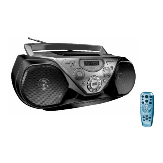
CD Sound Machine
TABLE OF CONTENTS
Technical Specification & Service tools ...........................2 - 1
Service Measurement......................................................2 - 2
Connections and controls.......................................3 - 1..3 - 2
Instructions for use .................................................3 - 3..3 - 4
Abbreviations and Pin-description of CD ICs ..................4 - 1
Disassembly Diagram......................................................4 - 2
Block Diagram .................................................................5 - 1
Wiring Diagram ................................................................5 - 2
Front part.................................................................6 - 1
Tuner part................................................................7 - 1
©
Copyright 2001 Philips Consumer Electronics B.V. Eindhoven, The Netherlands
All rights reserved. No part of this publication may be reproduced, stored in a retrieval
system or transmitted, in any form or by any means, electronic, mechanical, photocopying,
or otherwise without the prior permission of Philips.
Published by LX 0227 Service Audio
Printed in The Netherlands
Subject to modification
CD part 2 ................................................................8 - 2
Audio/supply part.....................................................9 - 1
Layout diagram (copper side)................................10 - 1
Layout diagram (component side).........................10 - 2
MP3CD2002 Board
Circuit diagram ......................................................11 - 1
Layout diagram......................................................11 - 2
Exploded view - cabinet.................................................12 - 1
Mechanical partslist .......................................................12 - 1
Electrical partslist .............................................13 - 1 .. 13 - 8
AZ 1538
all versions
CLASS 1
LASER PRODUCT
© 3140 785 32120
Advertisement
Table of Contents

Related Manuals for Philips AZ 1538


Summary of Contents for Philips AZ 1538
-
Page 1: Table Of Contents
LASER PRODUCT © Copyright 2001 Philips Consumer Electronics B.V. Eindhoven, The Netherlands All rights reserved. No part of this publication may be reproduced, stored in a retrieval system or transmitted, in any form or by any means, electronic, mechanical, photocopying, or otherwise without the prior permission of Philips. -
Page 2: Handling Chip Components
1 - 1 HANDLING CHIP COMPONENTS © ñ WARNING WAARSCHUWING All ICs and many other semiconductors are susceptible to Alle IC´s en vele andere halfgeleiders zijn gevoelig voor electrostatic discharges (ESD). Careless handling during electrostatische ontladingen (ESD). repair can reduce life drastically. Onzorgvuldig behandelen tijdens reparatie kan de levensduur When repairing, make sure that you are connected with the drastisch doen vermindern. -
Page 3: Technical Specifications
2 - 1 TECHNICAL SPECIFICATIONS GENERAL TUNER - AM SECTION SPECIFICATIONS Mains voltage -/00C : 230 V Tuning range MW : 531 - 1602 kHz -/01 : 120 / 230 V LW : 153 - 279 kHz Mains frequency -/00C : 50 Hz IF frequency : 450 kHz ±... -
Page 4: Service Measurement
2 - 2 SERVICE MEASUREMENT Bandpass Tuner SW LF Voltmeter 250Hz-15kHz Aerial replacement e.g. PM2534 e.g. 7122 707 48001 RF Generator Capacitor e.g. PM5326 S/N and distortion meter e.g. Sound Technology ST1700B To avoid atmospheric interference all AM-measurements have to be carried out in a Faraday«s cage. Use a bandpass filter (or at least a high pass filter with 250Hz) to eliminate hum (50Hz, 100Hz). -
Page 5: Connections And Controls
3 - 1 CONNECTIONS AND CONTROLS... - Page 6 3 - 2 CONNECTIONS AND CONTROLS...
-
Page 7: Instructions For Use
3 - 3 INSTRUCTIONS FOR USE... - Page 8 3 - 4 INSTRUCTIONS FOR USE...
- Page 9 3 - 5 TUNER ADJUSTMENT TABLE ( ECO6 FM/MW- and FM/MW/LW - versions with ferrite antenna) Waverange Input frequency Input Tuned to Adjust Output Scope/Voltmeter VARICAP ALIGNMENT 108MHz 5130 8V –0.2V 87.5 - 108MHz 87.5MHz 4.3V –0.5V (65.81 - 74, 87.5 - 108MHz) check (65.81MHz) (1.2V –0.5V)
-
Page 10: Abbreviations And Pin-Description Of Cd Ics
4 - 1 4 - 1 Abbreviations and Pin-description of CD ICs Abbreviations and Pin-description of CD ICs SERVO PROCESSOR SAA7325H SERVO PROCESSOR SAA7325H SYMBOL DESCRIPTION SYMBOL DESCRIPTION HFREF comparator common mode input microcontroller interface R/W and load control line input (4-wire bus mode) HFIN comparator signal input SILD... -
Page 11: Disassembly Diagram
4 - 2 4 - 2 DISASSEMBLY DIAGRAM A.TO REMOVE BOTTOM CABINET ASSEMBLY - Remove screws A1(3x20) 4pcs and screws A2(3x10) 2pcs (In CD Door). - Remove screws A3(3x16) 3pcs and A4(3x10) 3pcs. A1 (x4) C.TO REMOVE DECK MECHANISM - Remove screws C6(3x10) 10pcs. A2(x2) - Remove screws C7(2.5x10) 4pcs. -
Page 12: Block Diagram
5 - 1 5 - 1 BLOCK DIAGRAM +A_ON Head phone +A-ON SOURCE SELECTOR SWITCH MUTE To mp 5 MP3CD2002 4 OHM CD MODULE POWER POWER POWER AMPLIFIER AMPLIFIER AMPLIFIER +Tuner Tuner V.M. Vcc2 To mp ECO6 SEARCH MUTE CD MUTE TUNER MODULE TAPE MUTE To Tuner... -
Page 13: Wiring Diagram
5 - 2 5 - 2 WIRING DIAGRAM CD DOOR SWITCH MECHANISM 9V BATTERY BOARD TRANSFORMER VOLTAGE SELECTOR /01,/11,/19 110-127V 220-240V BLUE ORANGE BLACK SECONDARY MAINS SOCKET BATTERIES 1258 LAYOUT CELL TRANSFORMER TUNER 1820 ECO6 LAYOUT CELL MAINS SOCKET /00,/05,/10, /13,/16,/17 COMBI BOARD FRONT BOARD... -
Page 14: Combi Board - Circuit Diagram Front Part
6 - 1 6 - 1 COMBI BOARD - CIRCUIT DIAGRAM (FRONT PART) 1404 A2 1471 H12 1477 G14 1483 H13 1490 G1 2406 A10 2413 D3 2421 F9 2452 C13 2463 G7 3402 A11 3408 F7 3414 C11 3420 F6 3426 G12 3432 D1 3438 A11... -
Page 15: Tuner Part
7 - 1 7 - 1 COMBI BOARD - CIRCUIT DIAGRAM (TUNER PART) 1105 A2 4104 L7 1121 H20 4105 B12 1122 G20 4109 D5 2101 B5 4110 D5 TUNER BOARD ECO6 /PORTABLE AUDIO 2103 D9 5102 G4 AM-IF1 2104 A4 5103 H3 VERSION PROGRAMMING COMPONETS 2106 C5... -
Page 16: Combi Board - Circuit Diagram Cd Part 1
8 - 1 8 - 1 COMBI BOARD - CIRCUIT DIAGRAM (CD PART 1) 1800 C1 2816 F10 2823 B11 2831 F12 2838 G4 2863 B7 2872 B8 2879 E6 3802 A7 3809 A8 3816 C7 3823 E5 3830 E7 3837 C14 3846 F11 3853 H5... -
Page 17: Cd Part 2
8 - 2 8 - 2 COMBI BOARD - CIRCUIT DIAGRAM (CD PART 2) 1820 C3 2844 A5 2848 C5 2853 E7 3838 D1 3867 A5 3871 A7 3876 B6 3881 E7 3911 C1 7810-B C6 MP807 D10 MP823 D3 MP865 E7 MP871 D10 MP881 D3... -
Page 18: Audio/Supply Part
9 - 1 9 - 1 COMBI BOARD - CIRCUIT DIAGRAM (AUDIO/SUPPLY PART) 0001 G2 1316 A15 2303 H11 2322 B11 2348 A12 2360 B2 2372 B14 2506 B5 2518 A7 2531 D9 2543 G2 3308 F2 3322 G7 3332 D11 3505 C3 3514 A5 3522 B5... -
Page 19: Combi Board - Layout Diagram
10 - 1 10 - 1 COMBI BOARD - LAYOUT DIAGRAM (COPPER SIDE) 3471 3473 3430 3468 3470 3426 3477 3475 3476 3474 2412 3578 3584 3442 3443 4401 3446 3439 2419 3449 3421 2418 3498 3435 2468 3407 3436 3422 3402 3403 4403... -
Page 20: Layout Diagram (Component Side)
10 - 2 10 - 2 COMBI BOARD - LAYOUT DIAGRAM (COMPONENT SIDE) -
Page 21: Circuit Diagram
11 - 1 11 -1 CIRCUIT DIAGRAM - MP3CD2002 BOARD MP3-CD-2002 2451 B5 2452 B2 2453 B4 2454 B7 2455 C2 only for FLASH version 2456 C12 2457 D9 2450 3465 2458 C10 2459 D2 100n 100R +3.3V +core +3.3V 2460 E13 +3.3V 2461 D12... - Page 22 11- 2 11 - 2 LAYOUT DIAGRAM - MP3CD2002 BOARD 1460 A3 3449 C3 3460 C2 3482 B2 3492 A3 6450 C2 1451 B5 2457 A2 2469 B4 3469 C4 3479 A2 4450 A4 2456 A4 3452 B2 3461 B5 3483 B2 3493 B2 7450 B4...
-
Page 23: Mechanical Partslist
12 - 1 12 - 1 EXPLODED VIEW DIAGRAM - CABINET MECHANICAL PARTSLIST - CABINET 3140 114 42810 KNOB-VOKUME 3140 114 42920 KNOB-DBB/BAND 3140 117 63020 FRONT PANEL ASS’Y 3140 114 42820 CD BUTTON-PLAY/STOP SCREW LIST : 3140 114 42840 BUTTON-SEARCH T3 x 6 3140 114 42900... -
Page 24: Electrical Partslist
13 - 1 ELECTRICAL PARTSLIST - COMBI BOARD - MISCELLANEOUS - - CAPACITORS - 1106 3140 114 50050 FERRITE BAR 80MM( /00C) 2133 4822 124 22651 1µF 20% 50V 1106 2422 549 44211 FERRITE BAR( /01) 2134 3198 017 31530 15nF 10% X7R 50V 1257 2422 026 05076... - Page 25 13 - 2 ELECTRICAL PARTSLIST - COMBI BOARD - CAPACITORS - - CAPACITORS - 2347 4822 124 40433 47µF 20% 25V 2505 2020 552 94427 100pF 5% NP0 50V 2348 4822 124 40433 47µF 20% 25V 2506 2020 552 94427 100pF 5% NP0 50V 2351 4822 124 80195...
- Page 26 13 - 3 ELECTRICAL PARTSLIST - COMBI BOARD - CAPACITORS - - RESISTORS - 2841 4822 126 13879 220nF +80-20% 16V 3155 4822 051 30479 47R 5% 0,062W 2843 2020 552 94427 100pF 5% NP0 50V 3156 3198 021 31040 100K 5%( /01) 2844 4822 126 13883...
- Page 27 13 - 4 ELECTRICAL PARTSLIST - COMBI BOARD - RESISTORS - - RESISTORS - 3401 4822 116 52176 10R 5% 0,5W 3452 4822 051 30392 3,9K 5% 0,062W 3402 4822 051 30471 470R 5% 0,062W 3453 4822 051 30183 18K 5% 0,062W 3403 4822 051 30471 470R 5% 0,062W...
- Page 28 13 - 5 ELECTRICAL PARTSLIST - COMBI BOARD - RESISTORS - - RESISTORS - 3517 4822 051 30681 680R 5% 0,062W 3589 4822 051 30472 4,7K 5% 0,062W 3518 4822 051 30681 680R 5% 0,062W 3590 4822 051 30472 4,7K 5% 0,062W 3519 4822 051 30392 3,9K 5% 0,062W...
- Page 29 13 - 6 ELECTRICAL PARTSLIST - COMBI BOARD - RESISTORS - - RESISTORS - 3849 4822 051 30471 470R 5% 0,062W 3908 4822 051 30222 2,2K 5% 0,062W 3850 4822 051 30472 4,7K 5% 0,062W 3909 4822 117 13632 100K 1% 0,62W 3851 4822 117 10834 47K 1% 0,1W...
- Page 30 13 - 7 ELECTRICAL PARTSLIST - COMBI BOARD - COILS & FILTERS - - IC & TRANSISTORS - 5121 4822 242 10261 T6252F00 (75KHZ) 7101 9351 740 80557 TEA5757H/V1 5122 2422 549 44108 IND VAR 7MM 796KHZ 7102 4822 130 42131 BF550 5123 2422 549 44108...
- Page 31 13 - 8 ELECTRICAL PARTSLIST - MISCELLANEOUS - MISCELLANEOUS - 1200 ! 2422 030 00333 AC SOCKET 2P 1202 ! 2422 127 00453 VOLTAGE SELECTOR( /01) 1300 2422 264 00454 LOUDSPEAKER 1301 2422 264 00454 LOUDSPEAKER 1800 4822 267 11028 FFC CONNECTOR 16P 1820 2422 025 16978...