Table of Contents
Advertisement
Sno-Thro
Owner/Operator Manual
Models
926302 – ST1332LE
926310 – ST9526DLE
926311 – ST11528DLE
926312 – ST1332DLE
926313 – ST1336DLE
926314 – ST9526DLET
926315 – ST11528DLET
926316 – ST1332DLET
ENGLISH
FRANÇAIS
DEUTSCH
ITALIANO
SUOMI
ESPAGÑOL
NORSK
SVENSKA
РУССКИЙ ЯЗЫК
POLSKI
TÜRKÇE
ČESKY
®
03389515 5/08
Printed in USA
Advertisement
Table of Contents

Related Manuals for Ariens 926310-ST9526DLE


Summary of Contents for Ariens 926310-ST9526DLE
- Page 1 Sno-Thro ® Owner/Operator Manual Models 926302 – ST1332LE 926310 – ST9526DLE 926311 – ST11528DLE 926312 – ST1332DLE 926313 – ST1336DLE 926314 – ST9526DLET 926315 – ST11528DLET 926316 – ST1332DLET ENGLISH FRANÇAIS DEUTSCH ITALIANO SUOMI ESPAGÑOL NORSK SVENSKA РУССКИЙ ЯЗЫК POLSKI TÜRKÇE 03389515 5/08 ČESKY...
- Page 2 Nous, soussignés ARIENS COMPANY, certifions que : Der Unterzeichnete, ARIENS COMPANY, bescheinigt, dass: Wij, de ondergetekenden, ARIENS COMPANY, verklaren dat: Undertegnede, ARIENS COMPANY, attesterer, at: La sottoscritta società ARIENS COMPANY certifica che: Nosotros, los abajo firmantes, ARIENS COMPANY, certificamos que: Undertegnede, ARIENS COMPANY, bekrefter at: Undertecknad, ARIENS COMPANY, intygar att: Allekirjoittanut, ARIENS COMPANY, vakuuttaa, että: My, nijej...
- Page 3 Date Date Datum File) Responsable de la qualité et de la conformité des Datum Dato Data produits (Dépositaire de la fiche technique) Manager Fecha Dato Ariens Company Qualitätssicherung und Konformität (Archivar der Datum Päiväys Data Data Datum technischen Akte) Kwaliteits- en normalisatiemanager...
-
Page 4: Table Of Contents
PRODUCT REGISTRATION Numbers are located on the product The Ariens dealer must register the product registration form in the unit literature at the time of purchase. Registering the package. They are printed on a serial number product will help the company process label, located on the frame of your unit. -
Page 5: Safety
4. Review recommended lubrication, unit. maintenance and adjustments. 5. Review Limited Warranty Policy. 6. Fill out a Product Registration Card and return the card to the Ariens Company or go to www.ariens.com. SAFETY SAFETY ALERTS WARNING: To avoid injury to... -
Page 6: Safety Decals And Locations
SAFETY DECALS AND WARNING: POTENTIALLY LOCATIONS HAZARDOUS SITUATION! If not ALWAYS replace missing or damaged Safety avoided, COULD RESULT in death Decals. Refer to figures below for Safety or serious injury. Decal locations. CAUTION: POTENTIALLY HAZARDOUS SITUATION! If not avoided, MAY RESULT in minor or moderate injury. -
Page 7: Safety Rules
Complete a walk around inspection of unit Wear appropriate hearing and work area to understand: protection. • Work area • Your unit • All safety decals ALWAYS check overhead and side clearances carefully before operation. OL4690 ALWAYS be aware of traffic when operating along streets or curbs. - Page 8 ALWAYS keep hands away from all pinch Abnormal Vibrations are a warning of trouble. points. Striking a foreign object can damage unit. Immediately stop unit and engine. Remove DO NOT touch unit parts which might be hot key and wait for all moving parts to stop. from operation.
- Page 9 Fuel is highly flammable and its vapors are • Internal Contact: Drink large quantities of water. Follow with Milk of Magnesia, explosive. Handle with care. Use an beaten egg or vegetable oil. Get approved fuel container. medical attention immediately! NO smoking, NO sparks, NO flames. •...
-
Page 10: Assembly
ASSEMBLY 5. Install and tighten all wing knobs and wing nuts on the handlebar assembly WARNING: AVOID INJURY. Read and shift rod. and understand the entire Safety NOTE: The handlebar has two height section before proceeding. positions. Adjust the handlebar height to provide better operator comfort. - Page 11 NOTE: After the chute rod has been inserted through the hex hole in the control assembly, placing the unit in the service position (see Service Position on page 23) will ease alignment and installation of the hair pin. 8. Secure the chute rod to the control assembly with the hair pin removed in step 6 using the end hole location as shown in Figure 7.
- Page 12 NOTE: Press down on lock teeth with your finger to align the cable ball end with the slot (Figure 8). OS7070 OS7271 1. Cable Anchor 2. Cable End Figure 8 3. Deflector Cable 4. Cable Fitting 10. Replace the gear cover removed in 5.
- Page 13 CAUTION: Avoid injury! Explosive separation of tire and rim parts is possible when they are serviced incorrectly: • Do not attempt to mount a tire without the proper equipment and experience to perform the job. • Do not inflate the tires above the recommended pressure.
-
Page 14: Controls And Features
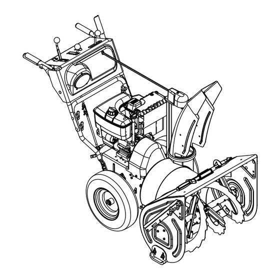
CONTROLS AND FEATURES 1. Attachment Clutch Lever 926302, 310, 311, 312, 313 2. Speed Selector 3. Deflector Remote Control 4. Chute Control 5. Traction Drive Clutch Lever 6. Oil Fill/Dipstick 7. Muffler Guard 8. Discharge Chute Deflector 9 10 9. Discharge Chute 10. - Page 15 1. Attachment Clutch Lever 926314, 315, 316 2. Speed Selector 3. Deflector Remote Control 2 3 4 4. Chute Control 5. Traction Drive Clutch Lever 6. Oil Fill/Dipstick 7. Discharge Chute Deflector 8. Discharge Chute 9. Impeller 10. Clean-out Tool 11.
-
Page 16: Operation
OPERATION Attachment Clutch - Right Hand WARNING: AVOID INJURY. Read Lever and understand the entire Safety section before proceeding. Squeeze Attachment Clutch Lever against handlebar (1) to WARNING: To avoid injury to hands engage attachment. and feet, always disengage Release both clutch clutches, shut off engine, and wait levers (2) to disengage for all movement to stop before... - Page 17 Forward: Snow Clean-Out Tool (6) Fastest (Figure 12) (1) Slowest Reverse: WARNING: Hand contact with the rotating impeller is the most (1) Slow common cause of injury associated (2) Fast with snow throwers. Never use your hand to clean out the discharge IMPORTANT: DO chute.
- Page 18 Discharge Chute Control Differential Lock (926314, 315, 316) (Figure 14) IMPORTANT: If chute does not stay in set position, adjust as directed in SERVICE AND The differential can be locked for maximum ADJUSTMENTS on page 26, or repair before traction or unlocked to allow for easier operation.
- Page 19 Scraper Blade The scraper blade allows the back of the housing to keep better contact with the surface being cleared. It also prevents damage to the housing from normal wear. IMPORTANT: DO NOT allow Scraper Blade to wear too far or Auger/Impeller housing will become damaged.
-
Page 20: Filling Fuel Tank
The fuel shut-off valve has two positions: Normal Closed Position: Use this position to service, transport, or store the unit. Transport Deep Cutting OS7117 Open Position: Use this position to run the unit. Figure 17 To add fuel to fuel tank: 1. - Page 21 2. Check Function of Clutches TO STOP IN AN EMERGENCY If clutches do not engage or disengage Immediately release both control levers to properly, adjust or repair before operation. stop unit in an emergency. Stop engine, See Attachment Clutch/Brake Adjustment on remove key and wait for all rotating parts to page 29 and Traction Drive Clutch stop before leaving operator’s position.
-
Page 22: Snow Removal
Electric Start (240V) IMPORTANT: DO NOT operate starter more than 15 seconds per minute, as overheating 1. Connect extension cord to starter. and damage can occur. (If engine does not IMPORTANT: Prevent damage to unit. Know start, refer to TROUBLESHOOTING on voltage of your starter and only use matching page 38.) outlets. -
Page 23: Maintenance
DO NOT transport machine while engine is running. MAINTENANCE Ariens Dealers will provide any service or MAINTENANCE SCHEDULE adjustments which may be required to keep The chart below shows the recommended your unit operating at peak efficiency. Should... -
Page 24: General Lubrication
See Attachment Clutch/Brake Adjustment on IMPORTANT: Use only Ariens special gear page 29 and Traction Drive Clutch lubricant L-2 (Part Number 00008000). Adjustment on page 32. - Page 25 Auger Shaft Remove corrosion from battery terminals and cable connections with a wire brush, then NOTE: To grease auger shaft, remove shear wash with a weak baking soda solution. bolt nuts, and shear bolts. Apply grease at the grease zerks and then turn the auger shaft. After cleaning, apply a thin coat of grease or Replace shear bolts per instructions in Shear petroleum jelly to terminals and cable ends to...
-
Page 26: Service And Adjustments
SHEAR BOLTS (housing closest to ground). 3. Reposition scraper blade flush with IMPORTANT: Use only Ariens shear bolts for runners and tighten lock nuts. replacement. Use of any other type of shear bolt may result in severe damage to unit. See RUNNERS SERVICE PARTS on page 37. - Page 27 OS7150 1. Auger 2. Shear Bolts Figure 24 For Replacement: 1. Align shear bolt holes in auger with OS7155 shear bolt holes in the shaft. 2. Drive shear bolt through hole (if shear bolt was broken this will drive remaining part from shaft).
-
Page 28: Discharge Chute
7. Check and adjust attachment clutch, 2. Loosen adjusting nuts on cable support speed selector and traction clutch. See bracket underneath the dash panel Speed Selector Adjustment on page 29 (Figure 28). and Traction Drive Clutch Adjustment on 3. To adjust the deflector lower: page 32. -
Page 29: Speed Selector Adjustment
3. Turn the speed selector lever straight down towards the ground as far as it will 4. Thread the adjustment pivot pin along the shift rod until it aligns with the mating Tighten upper hole on the speed selector lever. Insert adjustment nut. - Page 30 Check Attachment Idler Arm Roller Clearance NOTE: It will be difficult to check the measurement inside the frame. Use a 1/2 in. (12.7 mm) minimum spacer as a gauge to check the clearance between the roller and the frame. 1. With the clutch lever engaged, check the clearance between the frame and plastic roller on the lower end of the attachment idler arm.
- Page 31 Adjust the Attachment Clutch Cable Spring Extension 1. Check the attachment clutch cable spring extension. Measure the length of the attachment clutch cable spring with the clutch lever disengaged. Then measure the attachment clutch spring with the clutch lever engaged. See Figure 35.
-
Page 32: Traction Drive Clutch Adjustment
Check belt finger clearance here. With the attachment clutch engaged, there should be less than 1/8 in. (3 mm) clearance between the belts and the belt finger. The belt finger should not touch the belts. Minimum of 1/16 in. OS7201 (1.6 mm). - Page 33 IMPORTANT: If spring length cannot be adjusted within specified range, see your Dealer for repairs. ATTACHMENT DRIVE BELTS REPLACEMENT Remove old attachment drive belts: 1. Shut off engine, remove key, disconnect spark plug wire and allow unit to cool completely. 2.
- Page 34 IMPORTANT: With clutch lever engaged, belt finger on the side opposite the belt idler should be less than 1/8 in. (3 mm) from belts, but not touching the belts. Adjust belt finger as necessary. 5. Check adjustment. See Check Belt Finger Clearance on page 32.
- Page 35 9. Install pinion sprocket and chain on hex Replacing shaft, then replace bearing flanges. Use U1R or U1L; 240 CCA minimum @ 0°F 10. Hold wheel so friction disc will not rotate type batteries. and secure new friction disc to carrier with three hex screws removed in step TRACK TENSION ADJUSTMENT (926314, 315, 316)
-
Page 36: Storage
To treat the fuel system for storage: 1. Add fuel stabilizer (Ariens p/n 00592900) according to manufacturers’ instructions. 2. Run engine for at least 10 minutes after adding stabilizer to allow it to reach the carburetor. -
Page 37: Service Parts
SERVICE PARTS ACCESSORIES Order the following parts through your See your authorized Ariens dealer to add Dealer: the additional accessories available to your Sno-Thro. Part No. Description Part No. Description 00036800 Ariens Hi-Temp Grease (3, 3 oz. cartridges) 72406500 Front Weight Kit 00592900 Fuel Stabilizer 4 oz. -
Page 38: Troubleshooting
TROUBLESHOOTING PROBLEM PROBABLE CAUSE CORRECTION Engine will not 1. Fuel tank is empty. 1. Fill fuel tank. crank/start. 2. Fuel shut-off valve closed. 2. Open fuel shut-off valve. 3. Build up of dirt and residue 3. Clean area around around governor/carburetor. -
Page 39: Specifications
SPECIFICATIONS Model Number 926302 926310 926311 926312 Description ST1332LE ST9526DLE ST11528DLE ST1332DLE Engine - Tecumseh Tecumseh Tecumseh Tecumseh OH358SA OH318SA OH318SA OH358SA Power Max - kW (HP) 9.7 (13.0) 9.7 (13.0) 7.0 (9.5) 8.6 (11.5) Maximum RPM 3600 ± 150 Displacement - in. - Page 40 SPECIFICATIONS Model Number 926313 926314 926315 926316 Description ST1336DLE ST9526DLET ST11528DLET ST1332DLET Engine - Tecumseh Tecumseh Tecumseh Tecumseh OH358SA OH318SA OH318SA OH358SA Power Max - KW (HP) 9.7 (13.0) 7.0 (9.5) 8.6 (11.5) 9.7 (13.0) Maximum RPM 3600 ± 150 Displacement - in.
- Page 42 Ariens Company 655 West Ryan Street Brillion, WI 54110-1072 920-756-2141 Fax 920-756-2407 www.ariens.com...
Need help?
Do you have a question about the 926310-ST9526DLE and is the answer not in the manual?
Questions and answers