Table of Contents
Advertisement
Quick Links
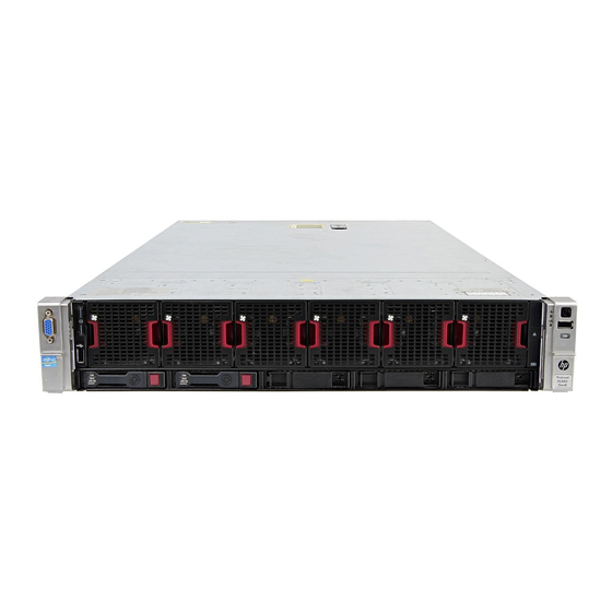
HP ProLiant DL560 Gen8 Server
User Guide
Abstract
This document is for the person who installs, administers, and troubleshoots servers and storage systems. HP assumes you are qualified in the
servicing of computer equipment and trained in recognizing hazards in products with hazardous energy levels.
Part Number: 696744-003
February 2014
Edition: 3
Advertisement
Table of Contents

Related Manuals for HP ProLiant DL560 Gen8


Summary of Contents for HP ProLiant DL560 Gen8
-
Page 1: User Guide
User Guide Abstract This document is for the person who installs, administers, and troubleshoots servers and storage systems. HP assumes you are qualified in the servicing of computer equipment and trained in recognizing hazards in products with hazardous energy levels. - Page 2 © Copyright 2012, 2014 Hewlett-Packard Development Company, L.P. The information contained herein is subject to change without notice. The only warranties for HP products and services are set forth in the express warranty statements accompanying such products and services. Nothing herein should be construed as constituting an additional warranty. HP shall not be liable for technical or editorial errors or omissions contained herein.
-
Page 3: Table Of Contents
Contents Component identification ....................... 6 Front panel components ..........................6 Front panel LEDs and buttons ......................... 6 Systems Insight Display LEDs ......................... 7 Systems Insight Display LED combinations ....................... 8 Rear panel components ..........................9 Rear panel LEDs and buttons ........................10 Non-hot-plug PCIe riser board slot definitions .................... - Page 4 Installing a full-length expansion board ....................57 Secondary PCIe riser cage option ........................ 58 2U rack bezel option ..........................60 HP Trusted Platform Module option ......................61 Installing the Trusted Platform Module board ..................62 Retaining the recovery key/password ....................63 Enabling the Trusted Platform Module ....................
- Page 5 Drivers ............................78 Software and firmware ........................78 Version control ..........................79 HP operating systems and virtualization software support for ProLiant servers ......... 79 HP Technology Service Portfolio ......................79 Change control and proactive notification ..................80 Troubleshooting .......................... 81 Troubleshooting resources ...........................
-
Page 6: Component Identification
Component identification Front panel components Item Description Video connector Serial pull tab USB connector Fan module Hot-plug hard drive Systems Insight Display Front panel LEDs and buttons Component identification 6... -
Page 7: Systems Insight Display Leds
** Facility power is not present, power cord is not attached, no power supplies are installed, power supply failure has occurred, or the power button cable is disconnected. Systems Insight Display LEDs The HP Systems Insight Display LEDs represent the system board layout. The display enables diagnosis with the access panel installed. Item... -
Page 8: Systems Insight Display Led Combinations
Item Description Status NIC link/activity Off = No link to network. If the power is off, view the rear panel RJ-45 LEDs for status ("Rear panel LEDs and buttons" on page 10). Flashing green = Network link and activity Solid green = Network link AMP status Off = AMP modes disabled Solid green = AMP mode enabled... -
Page 9: Rear Panel Components
Health LED Status Systems Insight Display System power LED and color that power supply is in standby. • Power supply fault • System board fault Amber Green One or more of the following conditions may Power supply (amber) exist: • Redundant power supply is installed and only one power supply is functional. -
Page 10: Rear Panel Leds And Buttons
iLO connector Serial connector FlexibleLOM ports (Shown: 4x1Gb/Optional: 2x10Gb); port 1 on right side Rear panel LEDs and buttons Item Description Status Power supply 1 Off = System is off or power supply has failed. Solid green = Normal Power supply 2 Off = System is off or power supply has failed. -
Page 11: System Board Components
FL/FH denotes full-length, full-height. HL/FH denotes half-length, full-height. LP denotes low profile. The PCIe 2-slot x16 riser cage supports a maximum power of 150 W with an HP power cable. This cable must be used for PCIe card wattages greater than 75 W. -
Page 12: System Maintenance Switch
Item Description Drive cage power connector 2 Processor 3 DIMM slots (1-6) Systems Insight Display connector Sideband signal connector Processor 4 DIMM slots (7-12) Processor 4 socket Discovery services connector Drive cage power connector 1 Front video connector Processor 4 DIMM slots (1-6) Processor 2 DIMM slots (1-6) Power supply backplane connector USB connector 1... -
Page 13: Nmi Functionality
NMI feature preserves that information by performing a memory dump before a hard reset. To force the OS to invoke the NMI handler and generate a crash dump log, the administrator can use the iLO Virtual NMI feature. For more information, see the HP website (http://www.hp.com/support/NMI). Component identification 13... -
Page 14: Dimm Slot Locations
DIMM slot locations DIMM slots are numbered sequentially (1 through 12) for each processor. The supported AMP modes use the letter assignments for population guidelines. Hot-plug drive bay numbering Hot-plug drive LED definitions Component identification 14... -
Page 15: Pcie Riser Cage Led
Item Status Definition Locate Solid blue The drive is being identified by a host application. Flashing blue The drive carrier firmware is being updated or requires an update. Activity ring Rotating green Drive activity No drive activity Do not remove Solid white Do not remove the drive. -
Page 16: Fbwc Module Leds (P222, P420, P421)
FBWC module LEDs (P222, P420, P421) The FBWC module has three single-color LEDs (one amber and two green). The LEDs are duplicated on the reverse side of the cache module to facilitate status viewing. 1 - Amber 2 - Green 3 - Green Interpretation The cache module is not powered. - Page 17 To avoid damage to server components, all fan modules must be installed in fan bays for any processor configuration. For all processor configurations, the HP ProLiant DL560 Gen8 Server requires six fan modules for redundancy. A fan failure causes a loss of cooling redundancy. A second fan failure or a missing fan module causes an orderly shutdown of the server.
-
Page 18: Operations
Operations Power up the server To power up the server, press the Power On/Standby button. Power down the server Before powering down the server for any upgrade or maintenance procedures, perform a backup of critical server data and programs. IMPORTANT: When the server is in standby mode, auxiliary power is still being provided to the system. -
Page 19: Access The Systems Insight Display
To reduce the risk of personal injury, be careful when pressing the server rail-release latches and sliding the server into the rack. The sliding rails could pinch your fingers. Access the Systems Insight Display To access the HP Systems Insight Display: Press and release the panel. Operations 19... -
Page 20: Remove The Access Panel
After the display fully ejects, rotate the display sideways to view the LEDs. Remove the access panel WARNING: To reduce the risk of personal injury from hot surfaces, allow the drives and the internal system components to cool before touching them. WARNING: To reduce the risk of personal injury, electric shock, or damage to the equipment, remove the power cord to remove power from the server. -
Page 21: Access The Product Rear Panel
Use a T-15 Torx screwdriver to tighten the security screw on the hood latch. Access the product rear panel Opening the cable management arm To access the server rear panel: Release the cable management arm. Open the cable management arm. Note that the cable management arm can be right-mounted or left-mounted. -
Page 22: Install The Primary Pcie Riser Cage
WARNING: To reduce the risk of personal injury, electric shock, or damage to the equipment, remove the power cord to remove power from the server. The front panel Power On/Standby button does not completely shut off system power. Portions of the power supply and some internal circuitry remain active until AC power is removed. -
Page 23: Remove The Air Baffle
Install the PCIe riser cage. Install the access panel (on page 20). Install the server into the rack ("Installing the server into the rack" on page 30). Connect each power cord to the server. Connect each power cord to the power source. Power up the server (on page 18). -
Page 24: Install The Air Baffle
CAUTION: Do not detach the cable that connects the battery pack to the cache module. Detaching the cable causes any unsaved data in the cache module to be lost. IMPORTANT: It is necessary to remove the PCI riser cage only if there is a full-length expansion board installed. - Page 25 Install the air baffle. Install the access panel (on page 20). Install the server into the rack ("Installing the server into the rack" on page 30). Connect each power cord to the server. Connect each power cord to the power source. Power up the server (on page 18).
-
Page 26: Setup
Setup Optional installation services Delivered by experienced, certified engineers, HP Care Pack services help you keep your servers up and running with support packages tailored specifically for HP ProLiant systems. HP Care Packs let you integrate both hardware and software support into a single package. A number of service level options are available to meet your needs. -
Page 27: Temperature Requirements
HP servers draw in cool air through the front door and expel warm air through the rear door. Therefore, the front and rear rack doors must be adequately ventilated to allow ambient room air to enter the cabinet, and the rear door must be adequately ventilated to allow the warm air to escape from the cabinet. -
Page 28: Power Requirements
Because of the high ground-leakage currents associated with multiple servers connected to the same power source, HP recommends the use of a PDU that is either permanently wired to the building’s branch circuit or includes a nondetachable cord that is wired to an industrial-style plug. NEMA locking-style plugs or those complying with IEC 60309 are considered suitable for this purpose. -
Page 29: Rack Warnings
Stack each same-colored pair of wires and then attach them to the same power source. The power cord consists of three wires (black, red, and green). For more information, see the HP 750W Common Slot -48V DC Input Hot-Plug Power Supply Installation Instructions. -
Page 30: Identifying The Contents Of The Server Shipping Carton
WARNING: To reduce the risk of personal injury or equipment damage when unloading a rack: • At least two people are needed to safely unload the rack from the pallet. An empty 42U rack can weigh as much as 115 kg (253 lb), can stand more than 2.1 m (7 ft) tall, and might become unstable when being moved on its casters. - Page 31 Install the power cord anchors. Secure the cables to the cable management arm. IMPORTANT: When using cable management arm components, be sure to leave enough slack in each of the cables to prevent damage to the cables when the server is extended from the rack. Connect the power cord to the AC power source.
-
Page 32: Installing The Operating System
Remote deployment installation—To remotely deploy an operating system, use Insight Control server deployment for an automated solution. For additional system software and firmware updates, download the HP Service Pack for ProLiant from the HP website (http://www.hp.com/go/spp/download). Software and firmware must be updated before using the server for the first time, unless any installed software or components require an older version. -
Page 33: Registering The Server
Registering the server To experience quicker service and more efficient support, register the product at the HP Product Registration website (http://register.hp.com). Setup 33... -
Page 34: Hardware Options Installation
Hardware options installation Introduction If more than one option is being installed, read the installation instructions for all the hardware options and identify similar steps to streamline the installation process. WARNING: To reduce the risk of personal injury from hot surfaces, allow the drives and the internal system components to cool before touching them. - Page 35 Open the heatsink retaining bracket, and then remove the blank, if present. CAUTION: The pins on the processor socket are very fragile. Any damage to them may require replacing the system board. Open each of the processor locking levers in the order indicated, and then open the processor retaining bracket.
- Page 36 Remove the clear processor socket cover. Retain the processor socket cover for future use. Install the processor. Verify that the processor is fully seated in the processor retaining bracket by visually inspecting the processor installation guides on either side of the processor. THE PINS ON THE SYSTEM BOARD ARE VERY FRAGILE AND EASILY DAMAGED.
- Page 37 CAUTION: Do not press down on the processor. Pressing down on the processor may cause damage to the processor socket and the system board. Press only in the area indicated on the processor retaining bracket. Press and hold the processor retaining bracket in place, and then close each processor locking lever. Press only in the area indicated on the processor retaining bracket.
-
Page 38: Memory Options
Install the heatsink. Install the air baffle (on page 24). Install any full-length expansion boards, if previously removed. Install the access panel (on page 20). Install the server into the rack ("Installing the server into the rack" on page 30). Connect each power cord to the server. - Page 39 • Single- and dual-rank PC3-10600 (DDR-1333) RDIMMs operating at up to 1333 MT/s at 1.35V • Single- and dual-rank PC3-12800 (DDR-1600) RDIMMs operating at up to 1600 MT/s at 1.5V • Single- and dual-rank PC3-12800 (DDR-1600) RDIMMs operating at up to 1600 MT/s at 1.35V •...
-
Page 40: Hp Smartmemory
IVB memory RDIMM supports 1.35V 3DPC at 1066. Third-party memory supports 1.5V 3DPC at 1066 MT/s. LRDIMM enables 3 DIMMs per channel. HP SmartMemory supports up to 3DPC at 1066 MT/s at 1.35V. Third-party memory supports 1.5V only. HP SmartMemory HP SmartMemory, introduced for Gen8 servers, authenticates and unlocks certain features available only on HP Qualified memory and verifies whether installed memory has passed HP qualification and test processes. -
Page 41: Single-, Dual-, And Quad-Rank Dimms
Single-, dual-, and quad-rank DIMMs To understand and configure memory protection modes properly, an understanding of single-, dual-, and quad-rank DIMMs is helpful. Some DIMM configuration requirements are based on these classifications. A single-rank DIMM has one set of memory chips that is accessed while writing to or reading from the memory. -
Page 42: Memory Configurations
E = UDIMM (unbuffered with ECC) L = LRDIMM (load reduced) For the latest supported memory information, see the QuickSpecs on the HP website (http://www.hp.com/go/productbulletin). At the website, choose the geographic region, and then locate the product by name or product category. -
Page 43: General Dimm Slot Population Guidelines
Advanced ECC provides additional protection over Standard ECC because it is possible to correct certain memory errors that would otherwise be uncorrected and result in a server failure. Using HP Advanced Memory Error Detection technology, the server provides notification when a DIMM is degrading and has a higher probability of uncorrectable memory error. -
Page 44: Installing A Dimm
Online spare population For Online Spare memory mode configurations, observe the following guidelines: • Observe the general DIMM slot population guidelines (on page 43). • Each channel must have a valid online spare configuration. • Each channel can have a different valid online spare configuration. •... -
Page 45: Hot-Plug Hard Drive Options
Connect each power cord to the power source. Power up the server (on page 18). Use RBSU ("HP ROM-Based Setup Utility" on page 74) to configure the memory mode. For more information about LEDs and troubleshooting failed DIMMs, see "Systems Insight Display LED combinations (on page 8)."... -
Page 46: Installing A Hot-Plug Sas Or Sata Hard Drive
CAUTION: For proper cooling, do not operate the server without the access panel, baffles, expansion slot covers, or blanks installed. If the server supports hot-plug components, minimize the amount of time the access panel is open. Determine the status of the drive from the hot-plug SAS drive LED combinations ("Hot-plug drive LED definitions"... -
Page 47: Controller Options
HP website (http://www.hp.com/go/smartstorage/docs). To configure arrays, see the HP Smart Storage Administrator User Guide on the HP website (http://www.hp.com/go/smartstorage/docs). Upgrade options exist for the integrated array controller. For a list of supported options, see the QuickSpecs on the HP website (http://www.hp.com/go/productbulletin). -
Page 48: Installing The Flash-Backed Write Cache Module
CAUTION: To prevent a server malfunction or damage to the equipment, do not add or remove the battery pack while an array capacity expansion, RAID level migration, or stripe size migration is in progress. CAUTION: After the server is powered down, wait 15 seconds and then check the amber LED before unplugging the cable from the cache module. -
Page 49: Installing The Flash-Backed Write Cache Capacitor Pack
Install the cache module. Connect the capacitor pack cable to the connector on the top of the cache module. Install the access panel (on page 20). Install the server into the rack ("Installing the server into the rack" on page 30). Connect each power cord to the server. - Page 50 To install the component: Back up all data. Close all applications. WARNING: To reduce the risk of personal injury, electric shock, or damage to the equipment, remove the power cord to remove power from the server. The front panel Power On/Standby button does not completely shut off system power.
- Page 51 Single capacitor pack holder Double capacitor pack holder Install the FBWC capacitor pack holder into the server. Hardware options installation 51...
-
Page 52: Redundant Hot-Plug Power Supply Option
Single capacitor pack holder Double capacitor pack holder Install the access panel (on page 20). Install the server into the rack ("Installing the server into the rack" on page 30). Connect each power cord to the server. Connect each power cord to the power source. Power up the server (on page 18). - Page 53 Connect the power cord to the power supply. Route the power cord. Use best practices when routing power cords and other cables. A cable management arm is available to help with routing. To obtain a cable management arm, contact an HP authorized reseller.
-
Page 54: Flexiblelom Option
FlexibleLOM option WARNING: To reduce the risk of personal injury, electric shock, or damage to the equipment, remove the power cord to remove power from the server. The front panel Power On/Standby button does not completely shut off system power. Portions of the power supply and some internal circuitry remain active until AC power is removed. -
Page 55: Expansion Board Options
To install the optional FlexibleLOM: Firmly seat the FlexibleLOM in the slot, and then tighten the thumbscrew. Install the PCIe riser cage ("Install the primary PCIe riser cage" on page 22). Install the access panel (on page 20). Slide the server into the rack. Connect the LAN segment cables. -
Page 56: Installing A Half-Length Expansion Board
Disconnect each power cord from the power source. Disconnect each power cord from the server. Extend the server from the rack (on page 18). Remove the access panel (on page 20). Disconnect any external cables that are connected to the expansion board. Disconnect any internal cables that are connected to the expansion board. -
Page 57: Installing A Full-Length Expansion Board
Install the expansion board. Connect any required internal or external cables to the expansion board. See the documentation that ships with the expansion board. Install the PCIe riser cage ("Install the primary PCIe riser cage" on page 22). Install the access panel (on page 20). Install the server into the rack ("Installing the server into the rack"... -
Page 58: Secondary Pcie Riser Cage Option
Remove the PCIe riser cage. Remove the expansion slot cover. Install the expansion board. Connect any required internal or external cables to the expansion board. See the documentation that ships with the expansion board. Install the PCIe riser cage ("Install the primary PCIe riser cage"... - Page 59 Disconnect each power cord from the power source. Disconnect each power cord from the server. Extend the server from the rack (on page 18). Remove the access panel (on page 20). Remove the PCI riser blank. Remove the blank from the optional secondary PCI riser cage. Hardware options installation 59...
-
Page 60: 2U Rack Bezel Option
Install an expansion board into the PCI riser cage. Install the optional secondary PCI riser cage. If not already installed, install the secondary processor ("Processor option" on page 34). Install the access panel (on page 20). Install the server into the rack ("Installing the server into the rack"... -
Page 61: Hp Trusted Platform Module Option
Retaining the recovery key/password (on page 63). Enabling the Trusted Platform Module (on page 63). Enabling the TPM requires accessing RBSU. For more information about RBSU, see the HP website (http://www.hp.com/support/rbsu). TPM installation requires the use of drive encryption technology, such as the Microsoft Windows BitLocker Drive Encryption feature. -
Page 62: Installing The Trusted Platform Module Board
Recovery Mode after BitLocker detects a possible compromise of system integrity. • HP is not liable for blocked data access caused by improper TPM use. For operating instructions, see the encryption technology feature documentation provided by the operating system. -
Page 63: Retaining The Recovery Key/Password
Install the TPM security rivet by pressing the rivet firmly into the system board. Install the air baffle (on page 24). Install the PCI riser cage ("Install the primary PCIe riser cage" on page 22). Install the access panel (on page 20). Install the server into the rack ("Installing the server into the rack"... - Page 64 OS application TPM settings. For more information on firmware updates and hardware procedures, see the HP Trusted Platform Module Best Practices White Paper on the HP website (http://www.hp.com/support).
-
Page 65: Cabling
Cabling SAS drive cabling Cabling 65... -
Page 66: Fbwc Cabling
FBWC cabling • SFF FBWC cabling • PCIe option Depending on the server configuration, you may need to remove the primary PCIe riser cage (on page 21) before cabling to a PCIe expansion board. 150W PCIe power cable option Cabling 66... - Page 67 CAUTION: To prevent damage to the server or expansion boards, power down the server and remove all AC power cords before removing or installing the PCI expansion cage. Connect the cable as indicated. Cabling 67...
-
Page 68: Software And Configuration Utilities
HP iLO The iLO subsystem is a standard component of HP ProLiant servers that simplifies initial server setup, server health monitoring, power and thermal optimization, and remote server administration. The iLO subsystem includes an intelligent microprocessor, secure memory, and a dedicated network interface. This design makes iLO independent of the host server and its operating system. -
Page 69: Active Health System
All key internal subsystems are monitored by iLO. SNMP alerts are sent directly by iLO regardless of the host operating system or even if no host operating system is installed. HP Insight Remote Support software (on page 72) is also available in HP iLO with no operating system software, drivers, or agents. -
Page 70: Intelligent Provisioning
The data that is collected is managed according to the HP Data Privacy policy. For more information see the HP website (http://www.hp.com/go/privacy). The Active Health System log, in conjunction with the system monitoring provided by Agentless Management or SNMP Pass-thru, provides continuous monitoring of hardware and configuration changes, system status, and service alerts for various server components. -
Page 71: Hp Insight Diagnostics
To access the Erase Utility, click the Perform Maintenance icon from the Intelligent Provisioning home screen, and then select Erase. For more information about the Erase Utility, see the HP Intelligent Provisioning User Guide on the HP website (http://www.hp.com/go/intelligentprovisioning/docs). Software and configuration utilities 71... -
Page 72: Hp Insight Remote Support Software
For more information, see HP Insight Remote Support and Insight Online Setup Guide for ProLiant Gen8 Servers and BladeSystem c-Class Enclosures on the HP website (http://www.hp.com/go/enterprise/docs). HP Insight Remote Support is available as part of HP Warranty, HP Care Pack Service, or HP contractual support agreement. -
Page 73: Scripting Toolkit For Windows And Linux
SPP is a comprehensive systems software (drivers and firmware) solution delivered as a single ISO file with major server releases. This solution uses HP SUM as the deployment tool and is tested on all supported HP ProLiant servers including HP ProLiant Gen8 servers. -
Page 74: Hp Rom-Based Setup Utility
Selecting the primary boot controller • Configuring memory options • Language selection For more information on RBSU, see the HP ROM-Based Setup Utility User Guide on the HP RBSU Information Library (http://www.hp.com/go/rbsu/docs). Using RBSU To use RBSU, use the following keys: •... -
Page 75: Boot Options
More than 6 To change any ORCA default settings and override the auto-configuration process, press the F8 key when prompted. For more information on RBSU, see the HP ROM-Based Setup Utility User Guide on the HP RBSU Information Library (http://www.hp.com/go/rbsu/docs). Boot options Near the end of the boot process, the boot options screen is displayed. -
Page 76: Utilities And Features
Gen8 servers, HP SSA replaces ACU with an enhanced GUI and additional configuration features. HP SSA exists in three interface formats: the HP SSA GUI, the HP SSA CLI, and HP SSA Scripting. Although all formats provide support for configuration tasks, some of the advanced tasks are available in only one format. -
Page 77: Rompaq Utility
ASR is a feature that causes the system to restart when a catastrophic operating system error occurs, such as a blue screen, ABEND (does not apply to HP ProLiant DL980 Servers), or panic. A system fail-safe timer, the ASR timer, starts when the System Management driver, also known as the Health Driver, is loaded. When the operating system is functioning properly, the system periodically resets the timer. -
Page 78: Redundant Rom Support
HP website (http://www.hp.com/go/spp/download). To locate the drivers for a particular server, go to the HP website (http://www.hp.com/go/hpsc) and click on Drivers, Software & Firmware. Then, enter your product name in the Find an HP product field and click Software and firmware Software and firmware should be updated before using the server for the first time, unless any installed software or components require an older version. -
Page 79: Version Control
HP Proactive Care—For customers running business critical environments where downtime is not an option, HP Proactive Care helps to deliver high levels of availability. Key to these service options is the delivery of proactive service management tools to help you avoid the causes of downtime. If a problem arises, then HP offers advanced technical response from critical system support specialists for problem identification and resolution. -
Page 80: Change Control And Proactive Notification
Change control and proactive notification HP offers Change Control and Proactive Notification to notify customers 30 to 60 days in advance of upcoming hardware and software changes on HP commercial products. For more information, refer to the HP website (http://www.hp.com/go/pcn). -
Page 81: Troubleshooting
• Simplified Chinese (http://www.hp.com/support/ProLiant_TSG_v1_sc) The HP ProLiant Gen8 Troubleshooting Guide, Volume II: Error Messages provides a list of error messages and information to assist with interpreting and resolving error messages on ProLiant servers and server blades. To view the guide, select a language: •... -
Page 82: Battery Replacement
Battery replacement If the server no longer automatically displays the correct date and time, you may need to replace the battery that provides power to the real-time clock. Under normal use, battery life is 5 to 10 years. WARNING: The computer contains an internal lithium manganese dioxide, a vanadium pentoxide, or an alkaline battery pack. - Page 83 IMPORTANT: Replacing the system board battery resets the system ROM to its default configuration. After replacing the battery, reconfigure the system through RBSU. To replace the component, reverse the removal procedure. For more information about battery replacement or proper disposal, contact an authorized reseller or an authorized service provider.
-
Page 84: Regulatory Information
Regulatory information Safety and regulatory compliance For safety, environmental, and regulatory information, see Safety and Compliance Information for Server, Storage, Power, Networking, and Rack Products, available at the HP website (http://www.hp.com/support/Safety-Compliance-EnterpriseProducts). Turkey RoHS material content declaration Ukraine RoHS material content declaration Warranty information HP ProLiant and X86 Servers and Options (http://www.hp.com/support/ProLiantServers-Warranties) -
Page 85: Electrostatic Discharge
Electrostatic discharge Preventing electrostatic discharge To prevent damaging the system, be aware of the precautions you need to follow when setting up the system or handling parts. A discharge of static electricity from a finger or other conductor may damage system boards or other static-sensitive devices. -
Page 86: Specifications
Weight (maximum) 18.59 kg (41.00 lb) Weight (minimum) Power supply specifications The server is configured with the HP 1200 W CS HE Power Supply (94%) ("HP 1200 W CS HE Power Supply (94%) specifications" on page 86). HP 1200 W CS HE Power Supply (94%) specifications... - Page 87 9.1 A at 100 VAC Rated input current 6.7 A at 200 VAC 897 W at 100V AC input Maximum rated input power 1321 W at 200V AC input 3408 at 120V AC input Btus per hour 4433 at 200V to 240V AC input Power supply output 800 W at 100V AC input Rated steady-state power...
-
Page 88: Support And Other Resources
Active Health System log (HP ProLiant Gen8 or later products) Download and have available an Active Health System log for 3 days before the failure was detected. For more information, see the HP iLO 4 User Guide or HP Intelligent Provisioning User Guide on the HP website (http://www.hp.com/go/ilo/docs). - Page 89 HP specifies in the materials shipped with a replacement CSR part whether a defective part must be returned to HP. In cases where it is required to return the defective part to HP, you must ship the defective part back to HP within a defined period of time, normally five (5) business days. The defective part must be returned with the associated documentation in the provided shipping material.
- Page 90 HP sono realizzati con numerosi componenti che possono essere riparati direttamente dal cliente (CSR, Customer Self Repair). Se in fase di diagnostica HP (o un centro di servizi o di assistenza HP) identifica il guasto come riparabile mediante un ricambio CSR, HP lo spedirà direttamente al cliente per la sostituzione.
- Page 91 Si, durante la fase de diagnóstico, HP (o los proveedores o socios de servicio de HP) identifica que una reparación puede llevarse a cabo mediante el uso de un componente CSR, HP le enviará dicho componente directamente para que realice su sustitución. Los componentes CSR se clasifican en dos categorías:...
- Page 92 HP se hará cargo de todos los gastos de envío y devolución de componentes y escogerá la empresa de transporte que se utilice para dicho servicio. Para obtener más información acerca del programa de Reparaciones del propio cliente de HP, póngase en contacto con su proveedor de servicios local.
- Page 93 Opcional – Peças cujo reparo feito pelo cliente é opcional. Essas peças também são projetadas para o reparo feito pelo cliente. No entanto, se desejar que a HP as substitua, pode haver ou não a cobrança de taxa adicional, dependendo do tipo de serviço de garantia destinado ao produto.
- Page 94 Support and other resources 94...
- Page 95 Support and other resources 95...
-
Page 96: Acronyms And Abbreviations
Acronyms and abbreviations ABEND abnormal end Array Configuration Utility Advanced Memory Protection Automatic Server Recovery Canadian Standards Association Customer Self Repair DDDC Double Device Data Correction double data rate FBWC flash-backed write cache International Electrotechnical Commission Integrated Lights-Out Integrated Management Log Acronyms and abbreviations 96... - Page 97 large form factor nonmaskable interrupt NVRAM nonvolatile memory ORCA Option ROM Configuration for Arrays PCIe Peripheral Component Interconnect Express POST Power-On Self Test RBSU ROM-Based Setup Utility RDIMM registered dual in-line memory module Rapid Deployment Pack serial attached SCSI SATA serial ATA SDDC Single Device Data Correction...
- Page 98 Systems Insight Manager TMRA recommended ambient operating temperature Trusted Platform Module UDIMM unregistered dual in-line memory module unit identification universal serial bus Version Control Agent Acronyms and abbreviations 98...
-
Page 99: Documentation Feedback
Documentation feedback HP is committed to providing documentation that meets your needs. To help us improve the documentation, send any errors, suggestions, or comments to Documentation Feedback (mailto:docsfeedback@hp.com). Include the document title and part number, version number, or the URL when submitting your feedback. -
Page 100: Index
6 FBWC module 16, 48 configuration of system 68 features 6, 76 connectors 6 Federal Communications Commission (FCC) contacting HP 88 notice 84 controller 47 firmware 78 CSR (customer self repair) 88 FlexibleLOM 54 customer self repair (CSR) 88... - Page 101 32, 79 HP Insight Remote Support software 72, 79 optical drive 6 HP Service Pack for ProLiant 68, 71, 73 optimum environment 26 HP Smart Update Manager overview 40, 68, 73 Option ROM Configuration for Arrays (ORCA) 68,...
- Page 102 SAS hard drive 45 removing the access panel 20 retaining the recovery key/password 63 warnings 29 ROM redundancy 78 website, HP 88 ROMPaq utility 68, 77, 78 safety considerations 29, 78, 84, 85 scripted installation 73 serial number 75...
Need help?
Do you have a question about the ProLiant DL560 Gen8 and is the answer not in the manual?
Questions and answers