Table of Contents
Advertisement
Congratulations on owning a Scag mower! This manual contains the operating
instructions and safety information for your Scag mower. Reading this manual
can provide you with assistance in maintenance and adjustment procedures to
keep your mower performing to maximum efficiency. The specific models that
this book covers are listed on the inside cover. Before operating your machine,
please read all the information enclosed.
© 2014
Scag Power Equipment
Division of Metalcraft of Mayville, Inc.
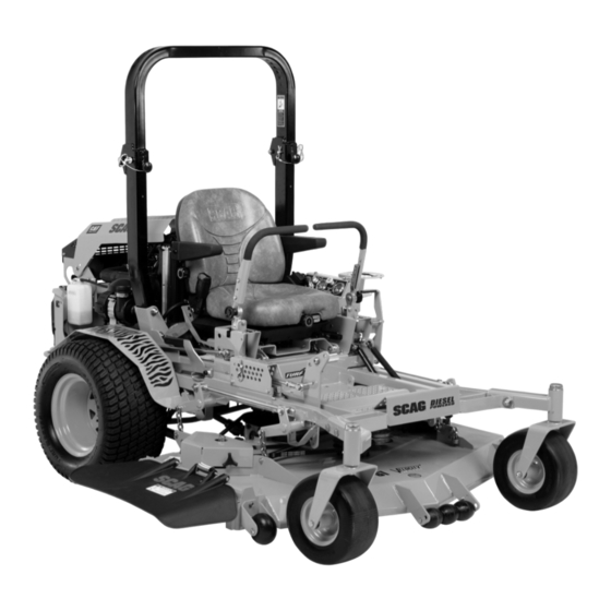
OPERATOR'S
MANUAL
Turf Tiger
Diesel Powered
Model:
STT61V-25KBD
STT72V-25KBD
STT-25KBD
PART NO. 03365
PRINTED 5/2014
PRINTED IN USA
Advertisement
Table of Contents

Related Manuals for Scag Power Equipment Turf Tiger STT61V-25KBD


Summary of Contents for Scag Power Equipment Turf Tiger STT61V-25KBD
- Page 1 STT61V-25KBD STT72V-25KBD STT-25KBD Congratulations on owning a Scag mower! This manual contains the operating instructions and safety information for your Scag mower. Reading this manual can provide you with assistance in maintenance and adjustment procedures to keep your mower performing to maximum efficiency. The specific models that this book covers are listed on the inside cover.
- Page 2 WARNING FAILURE TO FOLLOW SAFE OPERATING PRACTICES MAY RESULT IN SERIOUS INJURY OR DEATH. • Read this manual completely as well as other manuals that came with your mower. • DO NOT operate on steep slopes. To check a slope, attempt to back up it (with the cutter deck down).
-
Page 3: Table Of Contents
Table of Contents Table of Contents SECTION 1 - GENERAL INFORMATION ...................1 1.1 INTRODUCTION ............................1 1.2 DIRECTION REFERENCE ...........................1 1.3 SERvICING THE ENGINE AND DRIvE TRAIN COMPONENTS ..............1 1.4 SYMBOLS ..............................2 SECTION 2 - SAFETY INFORMATION ..................3 2.1 INTRODUCTION ............................3 2.2 SIGNAL WORDS ............................3 2.3 BEFORE OPERATION CONSIDERATIONS ....................3 2.4 OPERATION CONSIDERATIONS ........................4... - Page 4 7.12 COOLING SYSTEM ..........................39 7.13 BODY, DECK, AND UPHOLSTERY ......................40 SECTION 8 - ILLUSTRATED PARTS LIST ................42 8.1 SCAG APPROvED ATTACHMENTS AND ACCESSORIES..............42 61v & 72vS CUTTER DECKS .........................44 CUTTER DECK CONTROLS ...........................46 SHEET METAL COMPONENTS ........................48 STT ROLL-OvER PROTECTION SYSTEM .....................50 STT SUSPENSION SEAT ..........................52...
-
Page 5: General Information
Your mower was built to the highest standards in the Attachments and accessories manufactured by companies industry. However, the prolonged life and maximum other than Scag Power Equipment are not approved for use efficiency of your mower depends on you following the on this machine. See Section 8-1. -
Page 6: Symbols
Section 1 SYMBOLS SYMBOL DESCRIPTION SYMBOL DESCRIPTION Choke Transmission Parking Brake Spinning Blade 48071S On/Start Spring Tension on Idler Off/Stop Falling Hazard Thrown Object Hazard Fast Slow Continuously Variable - Linear Cutting Element - Basic Symbol Pinch Point Cutting Element - Engage 481039S Hour meter/Elapsed Operating Hours Cutting Element - Disengage... -
Page 7: Safety Information
Scag Service Dealer or by contacting Scag Power Equipment, Service Department at P.O. Box 152, Mayville, WI 53050 or contact us via the Internet at www.scag.com. The manual for this machine can be downloaded by using The signal word “CAUTION” is a reminder of safety practices... -
Page 8: Operation Considerations
Section 2 DO NOT allow children to ride or play on the Be sure the interlock switches are functioning machine, it is not a toy. correctly. Clear the area to be mowed of objects that could be Fuel is flammable; handle it with care. Fill the fuel picked up and thrown by the cutter blades. - Page 9 Section 2 Reduce speed and exercise extreme caution on Mow only in daylight or good artificial light. slopes and in sharp turns to prevent tipping or loss NEVER raise the deck with the blades engaged. of control. Be especially cautious when changing directions on slopes.
-
Page 10: Roll-Over Protection System
Section 2 Tie the mower down securely using straps, chains, WARNING cable, or ropes. Both front and rear straps must be directed down and outward from machine. Use care when approaching blind corners, shrubs, There is no roll-over protection when the roll bar trees, or other objects that may obscure vision. - Page 11 Section 2 Lower the roll bar only when absolutely necessary. WARNING To lower the roll bar, remove the hairpin cotter pins and remove the two (2) lock pins. See Figure 2-2. Failure to properly inspect and maintain the seat Lower the roll bar to the down position. belt can cause serious injury or loss of life.
-
Page 12: Maintenance Considerations & Storage
Section 2 MAINTENANCE CONSIDERATIONS & STORAGE Never make adjustments to the machine with the engine running unless specifically instructed to do so. If the engine is running, keep hands, feet, and clothing away from moving parts. Disengage drives, lower implement, set parking brake, stop engine and remove key or disconnect Figure 2-4. -
Page 13: Using A Spark Arrestor
If you need service on your hydraulic system, please see your authorized Scag dealer. Let the engine cool before storing. DO NOT store the machine near an open flame. -
Page 14: Safety And Instructional Decals
AVOID SERIOUS INJURY OR DEATH while ROPS is fully extended Read the Operators Manual and using seat belt Solicite etiquetas en espanol a un distribudo Scag If ROPS is foldable: Operate only on slopes you can back up & never Keep ROPS fully extended... -
Page 15: Specifications
Starter ......................Electric Starting with Solenoid Shift Starter Belts: ........................Kevlar cord. Self-adjusting, Self-tightening Deck Drive Belt ........................ Scag Part Number - 481460 Pump Drive Belt ....................Scag Part Number - 483678 - Kubota ELECTRICAL Battery ........................12 Volt, Maintenance Free (525CCA) Charging System ............................... Alternator Charging Output ............................ -
Page 16: Cutter Deck
Acres Per Day ........................23.7 ........28 The preceding chart will aid you in determining how many acres your Scag mower will cut per day. The chart is an estimate based on 8 hours per day cutting time at 6 MPH with an allowance for overlap and turns. -
Page 17: Operating Instructions
Section 4 OPERATING INSTRUCTIONS Mower Deck Switch (Figure 4-1). Used to engage CAUTION and disengage the mower drive system. Pulling up on the switch will engage the deck drive. Pushing down on the switch will disengage the deck drive. Do not attempt to operate this mower unless you Glow Plug Indicator (Figure 4-1). -
Page 18: Safety Interlock System
Section 4 Hour meter (Figure 4-1). Indicates the number of and lower the cutter deck. hours the engine has been operated. It operates Cutting Height Adjustment (Figure 4-1). Used to whenever the key is on. Has preset maintenance set the cutter deck at the desired cutting height. reminders for engine and hydraulic system oil changes. -
Page 19: Initial Run-In Procedures (First Day Of Use Or Approximately 10 Hours)
Section 4 INITIAL RUN-IN PROCEDURES (FIRST Allow engine to warm before operating the mower. DAY OF USE OR APPROxIMATELY 10 GROUND TRAvEL AND STEERING HOURS) Check all belts for proper alignment and wear at 2, 4 - IMPoRtANt - and 8 hours. If you are not familiar with the operation of a Change the engine oil and oil filter after the first 20 machine with lever steering and/or hydrostatic... -
Page 20: Engaging The Deck Drive (Cutter Blades)
Section 4 - IMPoRtANt - ENGAGING THE DECK DRIvE (CUTTER BLADES) Do not travel forward over a curb. The mower will hang up on the curb. Raise the deck and travel Set the throttle at about 3/4 speed. Do not attempt to backwards over the curb at a 45 degree angle. -
Page 21: Hillside Operation
Section 4 HILLSIDE OPERATION AFTER OPERATION Wash the entire mower after each use. Do not WARNING use high pressure spray or direct the spray onto electrical components. - IMPoRtANt - DO NOT operate on steep slopes. To check a slope, attempt to back up it (with the cutter deck down). -
Page 22: Moving Mower With Engine Stopped
Section 4 4.11 MOvING MOWER WITH ENGINE Cut grass when it is dry and not too tall. Do not cut grass too short (cut off 1/3 or less of existing grass STOPPED for best appearance). Mow frequently. Keep mower and discharge chute clean. To “free-wheel”... -
Page 23: Adjusting Cutting Height
Section 4 4.13 ADJUSTING CUTTING HEIGHT DECK RELEASE LEVER The mower deck can be adjusted from a height of 1.0 inch to 6.0 inches at 1/4-inch intervals. To adjust the cutting height: WARNING DO NOT adjust the cutting height with the mower blades rotating. -
Page 24: Adjusting The Steering Levers
Section 4 4.15 ADJUSTING THE STEERING LEvERS 4.16 TOWING (OPTIONAL HITCH ACCESSORY) Position the seat to the desired location. NEVER allow children or others in or on towed While in the operator's position with out the engine equipment. running, move both steering levers forward and reverse to check for full function control and comfort. -
Page 25: Troubleshooting Cutting Conditions
Section 5 TROUBLESHOOTING CUTTING CONDITIONS CONDITION CAUSE CURE STRINGERS - OCCASIONAL Low engine RPM Run engine at full RPM BLADES OF UNCUT GRASS Ground speed too fast Slow speed to adjust for conditions Wet grass Cut grass after it has dried out Dull blades, incorrect sharpening Sharpen blades Deck plugged, grass accumulation... - Page 26 Deck plugged, grass accumulation Clean underside of deck Too much blade angle (deck pitch) Adjust pitch and level Deck mounted improperly See your authorized SCAG dealer Bent spindle area See your authorized SCAG dealer Width of Deck Dull blade Sharpen blade...
- Page 27 Blades not mounted evenly Adjust pitch and level OF CUTTING PATH Bent blade Replace blade Internal spindle failure See your authorized SCAG dealer Mounting of spindle incorrect See your authorized SCAG dealer Width of Deck SGB024 SLOPE CUT - SLOPING RIDGES...
-
Page 28: Adjustments
“ENGAGE” position and the parking brake will allow the mower to move. If the following procedures do not allow you to engage the parking brake properly, contact your Scag dealer for further brake adjustments. 390S0152-1 Position a floor jack under the rear of the machine. -
Page 29: Travel Adjustments
Section 6 TRAvEL ADJUSTMENTS LOOSEN HERE Neutral or tracking adjustments will need to be made if: A. The steering control levers are in the neutral position and the machine creeps forward or backward. (Neutral Adjustment, See Below). B. The steering control levers are in the full forward position and the mower pulls to one side or the other when traveling in a forward direction. -
Page 30: Throttle Control Adjustments
CAUTION THROTTLE CONTROL ADJUSTMENTS The engine and drive unit can get hot during This adjustment must be performed by your Scag dealer operation causing burn injuries. Allow engine to ensure proper and efficient running of the engine. and drive components to cool before making any Should the throttle control need adjustment, contact your adjustments. -
Page 31: Belt Alignment
400 hours / 2 years, whichever occurs first. LOOSEN HERE BELT ALIGNMENT Belt alignment is important for proper performance of your Scag mower. If you experience frequent belt wear or breakage, see your authorized Scag service center for Figure 6-5. Cutter Deck Level Adjustment belt adjustment. - Page 32 Section 6 JAM NUT LANYARD LOOSEN HERE ADJUST HERE 390S0174-1 390S014A-2 Figure 6-6. Cutter Deck Level Adjustment HEIGHT ADJUSTMENT PEDAL Using a wrench on the jam nut (See Figure 6.6) turn Figure 6-7. Cutter Deck Height Adjustment the adjusting rods until the proper pitch is obtained on both the RH and the LH side of the cutter deck.
- Page 33 Section 6 - Note - C. 4-3/4" or 5-1/4" Position - (See Figure 6-9). Placing the baffle in either the 4-3/4" or 5-1/4" setting will If an adjustment had to be made, be sure that the enhance fall cutting (leaf pickup) and reduce cutter cutter deck can easily be locked into the transport deck "blowout".
-
Page 34: Electric Clutch Adjustment
Section 6 ELECTRIC CLUTCH ADJUSTMENT ADJUSTMENT NUTS The electric clutch serves two functions in the operation of the mower. In addition to starting and stopping the power flow to the cutter blades, the clutch also acts as a brake to assist in stopping blade rotation when the PTO is switched off or the operator presence circuit is interrupted. -
Page 35: Maintenance
Section 7 MAINTENANCE MAINTENANCE CHART - RECOMMENDED SERvICE INTERvALS HOURS PROCEDURE COMMENTS BREAK-IN (FIRST 10) Check all hardware for tightness Check hydraulic oil level See paragraph 7.3 Check all belts for proper See paragraph 7.8 alignment Check coolant level See paragraph 7.12 Check hydraulic fittings and hoses Use extreme caution when for leaks... -
Page 36: Lubrication
Section 7 MAINTENANCE CHART - RECOMMENDED SERvICE INTERvALS (CONT'D) HOURS PROCEDURE COMMENTS BREAK-IN (FIRST 10) Apply grease to fittings See paragraph 7.2 Check hardware for tightness Change engine oil filter See paragraph 7.4 Check hydraulic oil level See paragraph 7.3 Replace engine fuel filter See paragraph 7.5 Drain hydraulic system and replace... -
Page 37: Lubrication Fitting Points
Section 7 GREASE FITTING LUBRICATION LUBRICANT / INTERVAL LITHIUM MP WHITE GREASE 2125 ( 40 HOURS / WEEKLY ) CHASSIS GREASE ( 100 HOURS / BI-MONTHLY ) CHASSIS GREASE ( 200 HOURS / MONTHLY ) CHASSIS GREASE ( 500 HOURS / YEARLY ) 390S0145-2 Figure 7-1. -
Page 38: Hydraulic System
Section 7 HYDRAULIC SYSTEM - IMPoRtANt - The hydraulic oil should be changed if you notice the presence of water or a rancid odor to the A. CHECKING HYDRAULIC OIL LEvEL hydraulic oil. The hydraulic oil level should be checked after the first 10 Park the mower on a level surface and stop the hours of operation. -
Page 39: Engine Oil
Section 7 ENGINE FUEL SYSTEM Run the engine at idle speed with the speed control lever in neutral for five minutes. Check the oil level in the hydraulic tank. It must be DANGER 3" inches from the top of the filler neck. If necessary, add SAE 20W50 motor oil. -
Page 40: Engine Air Cleaner
Section 7 ENGINE AIR CLEANER WARNING A. CLEANING AND/OR REPLACING AIR CLEANER ELEMENT Battery posts, terminals, and related accessories contain lead and lead compounds, chemicals For any air cleaner, the operating environment dictates the known to cause cancer and reproductive harm. air cleaner service periods. -
Page 41: Drive Belts
- Note - B. BLADE SHARPENING If you experience frequent belt wear or breakage, see your authorized Scag service center for belt - Note - adjustment. If possible, use a file to sharpen the blade. Using a wheel grinder may burn the blade. -
Page 42: Tires
Check the balance of the blade. If the blades are out SPACER of balance, vibration and premature wear can occur. See your authorized Scag dealer for blade balancing or special tools, if you choose to balance your own CUTTER blades. -
Page 43: Cutter Deck Gearbox
Section 7 7.11 CUTTER DECK GEARBOx B. CHANGING LUBRICANT The lubricant in the cutter deck gearbox should be changed A. CHECKING LUBRICANT LEvEL every 500 hours of operation or yearly, whichever occurs first. CAUTION Place a suitable container beneath the cutter deck gearbox and locate the gearbox drain plug. -
Page 44: Body, Deck, And Upholstery
Fill to Bottom of Filler Neck Periodically check the fan belt tension. The belt should deflect 1/2" with 10 pounds of pressure. See your Scag dealer if the belt is in need of adjustment or replacement. 7.13 BODY, DECK, AND UPHOLSTERY... - Page 45 Section 7...
-
Page 46: Illustrated Parts List
Section 8 ILLUSTRATED PARTS LIST SCAG APPROvED ATTACHMENTS AND ACCESSORIES Attachments and accessories manufactured by companies other than Scag Power Equipment are not approved for use on this machine. Scag approved attachments and accessories: • GC-3B (p/n 900S) - Requires a 900X (61 STT/SCZ Install Kit) (61" Cutter Deck Models Only) •... - Page 47 Section 8 ILLUSTRATED PARTS LIST NOTES...
-
Page 48: 61V & 72Vs Cutter Decks
Section 8 61v & 72vS CUTTER DECKS 14 15 16 72V Only 54 55 2012 STT61V CD... - Page 49 Section 8 61v & 72vS CUTTER DECKS Ref. Ref. Part No. Description Part No. Description 424841 Baffle, Custom Cut 61V 481625-01 Wing Nut, 3/8-16 424917 Baffle, Custom Cut 72V 462360 Belt Cover Assembly 04003-23 Bolt, Carriage 3/8-16 x 1” 462398 Belt Cover Assy., RH 424209 Discharge Baffle 61V...
-
Page 50: Cutter Deck Controls
Section 8 CUTTER DECK CONTROLS CUTTER DECK STT-28CAT 2008CDC... - Page 51 Section 8 CUTTER DECK CONTROLS Ref. Part No. Description 481764 Link, Deck Lift 04020-28 Nut, Jam 1/2-20 LH 481766 Rod End, Female - 1/2-20 LH 04050-10 Ring, Retaining 1/2” External “E” 45905 Bellcrank Weldment, RH Rear 43487 Pin, Decklift 482429 Slide Weldment, Height Adjustment 04009-02 Bolt, Shoulder 1/2 x 3/4”...
-
Page 52: Sheet Metal Components
Section 8 SHEET METAL COMPONENTS STT-25KBD 2008 SMC... - Page 53 Nut, Elastic Stop 3/8-16 43606 Spacer Bushing 462147 Seat Plate Weldment w/Decal 451481 Fender Weldment, RH 04003-01 Bolt, Carriage 1/4-20 x 6” Battery (not avail. through Scag) 422682 Cover, Battery 04003-12 Bolt, Carriage 5/16-18 x 3/4” 462007 Plate, Battery Box 48661 Rubber Pad 04029-01 Wing Nut, 1/4-20 x 3/4”...
-
Page 54: Stt Roll-Over Protection System
Section 8 STT ROLL-OvER PROTECTION SYSTEM... - Page 55 Section 8 STT ROLL-OvER PROTECTION SYSTEM Ref. Part No. Description 462210 STT, ROPS 04001-87 Bolt, Hex Head 1/2-13 x 4” 04021-19 Nut, Center Lock 1/2-13 04040-13 Flatwasher, 1/2-.562 x 1.375 x .109 484168 Pin Assembly (incl. #9 & #10) 04001-163 Bolt, Hex Head 1/2-13 x 3-3/4”...
-
Page 56: Stt Suspension Seat
Section 8 STT SUSPENSION SEAT... - Page 57 Section 8 STT SUSPENSION SEAT Ref. Part No. Description 922A Suspension Seat Assembly w/seat belt 484709 Armrest Kit, LH 484717 Seat Belt Kit 484711 Recliner Knob Kit 484710 Armrest Kit, RH 484712 Back Cover 481638 Seat Switch 484713 Track Kit 484714 Suspension Knob Kit 484708...
-
Page 58: Deck Drive Components
Section 8 DECK DRIvE COMPONENTS 19 11 Frame STT KBD 2014 DDC... - Page 59 Section 8 DECK DRIvE COMPONENTS Ref. Ref. Part No. Description Part No. Description 482433 Rod Assembly, Clutch Anti-Rotation 04019-02 Nut, Serrated Flange 1/4-20 04001-11 Bolt, Hex Head 5/16-18 x 1-1/2” 423925 Belt Guard, Rear 04040-04 Flatwasher, 5/16” 04003-07 Bolt, Carriage 1/4-20 x 1/2” 423465 Bracket, Anchor, Anti-Rotation 04003-02...
-
Page 60: Engine & Attaching Parts - Kubota Diesel
Section 8 ENGINE & ATTACHING PARTS - KUBOTA DIESEL RADIATOR NEGATIVE BATTERY CABLE STT KBD 2014... - Page 61 04017-16 Bolt, Hex Hd. Serr. Flng. 5/16-18 x 3/4” 483387 Gasket, Muffler 04003-12 Bolt, Carriage 5/16-18 x 3/4” 483335 ** Engine, Kubota (not avail. through Scag) 04019-03 Nut, Serr. Flng. 5/16-18 481811 Oil Pressure Sender 483513 Foam, Radiator Screen Upper 483433 Elbow, 45 Deg.
-
Page 62: Brake And Steering Components
Section 8 BRAKE AND STEERING COMPONENTS TO RH PUMP TO LH PUMP STT DB&SC... - Page 63 Section 8 BRAKE AND STEERING COMPONENTS Ref. Ref. Part No. Description Part No. Description 48343-04 Clevis, Traction Control 482340 Grip, Handle Bar 04064-02 Pin, Clevis 461914 Handle Bar, LH (Includes item 1) 04062-01 Hair Pin Cotter 461923 Handle Bar, RH (Includes item 1) 04004-49 Rod, Parking Brake 04001-09...
-
Page 64: Fuel And Hydraulic System - Kubota Diesel
Section 8 FUEL AND HYDRAULIC SYSTEM - KUBOTA DIESEL 43 (2) 43 (2) 44 45 50 INJECTION PUMP RIGHT FRAME 68 67 RAIL FROM FUEL RAIL 2007 STT-BSD F&HS.eps... - Page 65 Section 8 FUEL AND HYDRAULIC SYSTEM - KUBOTA DIESEL Ref. Ref. Part No. Description Part No. Description 04060-09 Roll Pin, Spring 3/16 x 3/4” 04110-01 U-Nut 1/4-20 04017-05 Bolt, Hex Serr. Flng., 1/4-20 x 3/4” 48136-13 Hose Clamp, 0.69” Dia. 483620 *** Fuel Hose, 5/16”...
-
Page 66: Bdp-16A Hydraulic Pump Assembly With Cooling Fan
Section 8 BDP-16A HYDRAULIC PUMP ASSEMBLY WITH COOLING FAN PORT "A" SIDE PORT "B" SIDE... - Page 67 Section 8 BDP-16A HYDRAULIC PUMP ASSEMBLY WITH COOLING FAN Ref. Part No. Description HG70740 Overhaul Seal Kit HG51455 Valve Plate HG70735 Cylinder Block Kit - 16cc HG51462 Thrust Ball Bearing Assembly HG51436 Variable Swashplate HG2000015 Slot Guide HG2000014 Trunnion Arm HG2000025 Block Spring HG2000024...
-
Page 68: Electrical System - Kubota Diesel
Section 8 ELECTRICAL SYSTEM - KUBOTA DIESEL GLOW PLUGS STARTER 2008STTKBD-EES... - Page 69 Part No. Description 481176-10 Cable, Positive Battery 481176-11 Cable, Negative Battery 462011 Clutch, Electric PTO 481808 Module, Interlock Battery (not available through Scag) 483957 Switch, PTO 48798 Switch, Key (Incl. Nut and Lockwasher) 48017-03 Nut, 5/8-32 Special 48017-04 Lockwasher 5/8” 483356...
-
Page 70: Replacement Decals And Information Plates
AVOID SERIOUS INJURY OR DEATH READ OPERATOR'S MANUAL Read the Operators Manual Solicite etiquetas en espanol a un distribudo Scag Operate only on slopes you can back up & never on slopes greater than 15 degrees If machine stops going up hill, stop blades and... - Page 71 Description 483727 Decal, Scag Logo 483407 Decal, Danger-Spinning Blades 48404 Decal, Metalcraft-Made In USA 483406 Decal, Warning-Rotating Blades 483509 Decal, Scag Diesel Powered 484292 Decal, Fuel Tank 481664 Decal, Stripes-RH 483201 Decal, 61” Velocity Plus 481663 Decal, Stripes-LH 483693 Decal, 72” Velocity Plus...
-
Page 72: Electrical Schematic - Kubota Diesel
Section 8 ELECTRICAL SCHEMATIC - KUBOTA DIESEL MODULE RELAY PLUG GLOW PLUG 20 AMP FUSE FUEL SHUTOFF SOLENOID WATER TEMP SENDER ALTERNATOR GLOW PLUG RELAY STARTER BRAKE SOLENOID INTERLOCK PURPLE WHT W/PURPLE STRIPE SWITCH BLACK PULL COIL WHITE RELAY 20 AMP FUSE FUEL PUMP YELLOW 50 AMP... -
Page 73: Limited Warranty - Commercial Equipment
Cutter decks are warranted against cracking for a period of three (3) years. (parts and labor 1st and 2nd year; parts only 3rd year.) The repair or replacement of the cutter deck will be at the option of Scag Power Equipment. We reserve the right to request components for evaluation. - Page 74 © 2013 Scag Power Equipment Division of Metalcraft of Mayville, Inc.
Need help?
Do you have a question about the Turf Tiger STT61V-25KBD and is the answer not in the manual?
Questions and answers