
Related Manuals for Enviro EF-II I


Summary of Contents for Enviro EF-II I
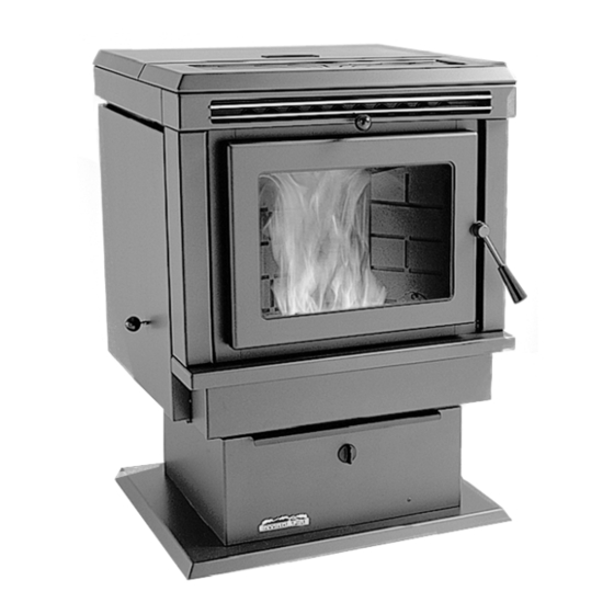
- Page 1 PELLET STOVE EF-ΙΙ i OWNER’S TECHNICAL MANUAL SHERWOOD INDUSTRIES LTD. 6782 OLDFIELD ROAD VICTORIA, BRITISH COLUMBIA V8M-2A3...
-
Page 2: Table Of Contents
ENVIROFIRE INSTALLATION MANUAL TABLE OF CONTENTS INTRODUCTION Important Safety Data..............3 Pellet Quality ...................4 Warnings and Recommendations............5 Automatic Safety Features ..............5 OPERATION How to Start Your Pellet Stove ............6 Turning Your Pellet Stove Off ............6 Slider Damper..................7 SPECIFICATIONS / MAINTENANCE Areas for Routine Maintenance ............8-9 Electrical Component Functions ..........10-11 INSTALLATION Deciding Where to Locate Your Pellet Stove.........12... -
Page 3: Important Safety Data
IMPORTANT SAFETY DATA Please read this entire manual before installation and use of this pellet fuel burning room heater. Failure to follow these instructions could result in property damage, bodily injury or even death. CAUTION: DO NOT CONNECT OT ANY AIR DISTRIBUTION DUCT OR SYSTEM; DO NOT BURN GARBAGE OR FLAMABLE FLUIDS SUCH AS GASOLINE, NAPTHA OR ENGINE OIL;... -
Page 4: Pellet Quality
PELLET QUALITY IS IMPORTANT, PLEASE READ THE FOLLOWING PAGE Your pellet stove has been designed to burn wood pellets only. Since there are many manufacturers of wood pellets it is important to select pellets that are free of dirt or any impurities. The Pellet Fuel Industries (P.F.I.) has established standards for wood pellet manufactures. -
Page 5: Warnings And Recommendations
WARNINGS AND RECOMMENDATIONS Do not abuse the glass by striking or slamming the door shut. Do not attempt to operate the stove with broken glass. Do not attempt to open the door and clean the glass while the unit is in operation. If you must clean the glass, use a soft cotton cloth and mild window cleaner. -
Page 6: How To Start Your Pellet Stove
HOW TO START YOUR PELLET APPLIANCE 1. Fill hopper with pellets. 2. Switch the power on by pushing the rocker switch to the manual position. CONTROLLER 3. Turn Dial A Fire knob to the 12 o’clock position. (The lower grade pellets may need a higher setting on the feed rate.) 4. -
Page 7: Operation
SLIDER/DAMPER INSTALLATION /OPERATIONS INSTRUCTIONS This is used to regulate the airflow through the pellet stove. INSTALLATION: 1. Remove the slider rod (short rod with knob and nuts) and the two nuts from their package and open the left side panel. This is the smaller of the two rods. Remove the knob from the knob. 2. -
Page 8: Areas For Routine Maintenance
AREAS FOR ROUTINE INSPECTION The following should be inspected periodically to ensure that the appliance is operating at its optimum and giving you excellent heat value: 2-3 DAYS/WEEKLY SEASONALLY or 2 TONS OF FUEL Burn Pot and Liner Exhaust Vent and Fresh Air Intake Tube Ash Pan Blower Mechanisms Inside Firebox... -
Page 9: Installation
DOOR GLASS (It is recommended that your dealer replace the glass if broken.) The door glass is made of 5 mm thick, high temperature PYROCERAMIC The center panel is 229 mm x 330 mm. To replace the glass, unscrew and remove the four glass retainers. Remove the glass and any broken pieces. High temperature fiberglass tape should be used around the glass. -
Page 10: Electrical Component Functions
ELECTRICAL COMPONENT FUNCTIONS The following is a list of electrical components and their functions on the ENVIROFIRE EF-IIi pellet stove. CONVECTION FAN CONTROLLER This controller is responsible for varying the speed of the convection blower. The stove has a fan control-over- ride. - Page 11 160°F (71°C) TEMPERATURE SENSOR When this sensor (located on the left side firewall) reaches 160°F (71°C), the convection blower will go to high, cooling the unit. 120°F (49°C)- N/O TEMPERATURE SENSOR (SHUT DOWN SENSOR) This sensor (mounted on the exhaust blower housing) has two functions (only if the auto/manual switch is in the auto position): -Should the fire happen to go out, this sensor will shut the stove off when the exhaust temperature drops below 120°F (49°C)
-
Page 12: Deciding Where To Locate Your Pellet Stove
DECIDING WHERE TO LOCATE YOUR PELLET APPLIANCE Check clearances to combustibles. Do not obtain combustion air from an attic, garage or any unventilated space. Combustion air may be obtained from a ventilated crawlspace. Do not install the stove in a bedroom. You can vent the stove through an exterior wall behind the unit or connect it to an existing masonry or metal chimney (must be lined if the chimney is over 6”... -
Page 13: Removing Your New Stove From It's Pallet
REMOVING YOUR NEW STOVE FROM IT’S PALLET To remove your new stove from its pallet, open the left and right side panels. There are two wood screws that are holding the bottom of the stove to the pallet. Remove the screws. Close the side panels. See PAGE 18 how to install the pedestal. -
Page 14: Masonry Fireplace Insert Installation
MASONRY FIREPLACE INSERT INSTALLATION, MODEL FPI The Fireplace insert model includes a surround faceplate and a pedestal. When installing this unit, ensure that the pedestal is removed from the inside of the hopper and installed on the bottom of the unit. -
Page 15: Assembling The Face Plate For The Fpi And Bih
ASSEMBLING THE FACE PLATE FOR THE FPI AND BIH MODELS 1. Assemble the brass frame using the corner hardware and screws supplied in the face place packaging. Install corner hardware into the side brass, then push into the top frame. Do not over- tighten or the side bass cannot be removed during servicing. -
Page 16: Model Bih Recommended Framing
RECOMMENDED FRAMING FOR BUILT IN HEATER When installing model BIH it is recommended that you use the dimensions shown in the diagram below. These clearances will make it easy and readily accessible for service. BUILT IN HEATER CLEARANCES TO COMBUSTIBLES This unit includes a 3”... -
Page 17: Clearances And Alcove Clearances
CLEARANCES TO COMBUSTIBLES CLEARANCE TO COMBUSTIBLES (FREESTANDING) - Side wall to unit A- 6 INCHES (150 mm) - Back wall to unit B- 1 INCH (25 mm) - Corner to unit C- 1 INCH (25 mm) - Mantle (Hearth Mount) 8 INCHES ( - Combustible flooring underneath the unit and extending 6 INCHES (150 mm) to the sides and front must be protected by a non combustible material. -
Page 18: Model Fs (Freestanding) Installation
MODEL FS (FREESTANDING) INSTALLATION PEDESTAL INSTALLATION Model FS comes with a pedestal that has to be attached prior to installation: Remove the pedestal from the box Remove the ENVIROFIRE unit from the box Place the unit on its back, making sure not to damage the wiring. -
Page 19: Horizontal Exhaust Through The Wall
HORIZONTAL EXHAUST THROUGH THE WALL NOTE: Use only listed type “PL” or “L” pellet venting products. Failure to use listed components may cause damage or personal injury or death. Choose a location for your stove that meets the requirements stated in this manual and allows installation with the least amount of interference to house framing, plumbing, wiring, etc. - Page 20 THROUGH WALL INSTALLATION 1”...
-
Page 21: Freestanding Inside Vertical Installation
INSIDE VERTICAL INSTALLATION, MODEL FS Choose a stove location that is ideal. See the section Deciding Where to Locate Your Pellet Appliance. Place on a noncombustible hearth pad where necessary. Place the unit on a hearth pad and space it in a manner so when the pellet vent is installed vertically, it will be 3”... -
Page 22: Freestanding Outside Vertical Pipe Installation
OUTSIDE VERTICAL PIPE INSTALLATION To accomplish the above titled installation, follow steps 1 through 8 in the previous section (HORIZONTAL EXHAUST THROUGH THE WALL) and then finish it by performing the following: Install a tee with clean out on the outside of the house. 10 Install PL vent upward from the tee. -
Page 23: Mobile Home Installation
MOBILE HOME INSTALLATION Secure the heater to the floor using the two bolt holes in the pedestal. CAUTION: THE STUCTURAL INTEGRITY OF THE MANUFACTURED HOME FLOOR, WALL, AND CEILING/ROOF MUST BE MAINTAINED. Ensure the unit is electrically grounded to the chassis of your home (permanently). Do not install in a room people sleep in. -
Page 24: Troubleshooting
TROUBLESHOOTING DO NOT: Switch the stove ON and OFF rapidly. This may cause current spikes, which could shorten the life of the electrical components. Service the stove with wet hands. The stove is an electrical appliance, which may pose a shock hazard if handled improperly. - Page 25 The stove will not function in the “AUTO” mode when hot If the unit fails to operate, by-pass the auto side of the switch by inserting a jumper wire between the dual black wires and the dual brown wires located on the back of the switch. Plug the stove back in. if the stove operates , Replace the switch.
- Page 26 POTENTIOMETER READINGS: Full clockwise (switched off) = open circuit, overload or infinite resistance LOW FIRE 800K OHMS to 900K OHMS HIGH FIRE 68K OHMS to 82K OHMS If the range does not vary or the switch does not close then replace the potentiometer. The stove will not shut down Make sure the auto/manual switch is in the auto position.
-
Page 27: Wiring Diagram
WIRING DIAGRAM... -
Page 28: Parts List
PARTS LIST EF-001 AUGER MOTOR EF-087 GOLD DOOR COMPLETE EF-002 CONVECTION BLOWER EF-088A LOG SET (20-036) EF-004 CONVECTION BLOWER IMPELLER EF-089 FS PEDESTAL BRASS TRIM EF-007 COMBUSTION BLOWER COMPLETE EF-091 BRASS TRIM SET EF-008 COMBUSTION MAIN IMPELLER EF-096 EF2 STOVE TOP EF-009 COMBUSTION COOLING IMPELLER EF-097... - Page 29 DECORATIVE TRIVET EF-148 PAINTED CONTROL EF2/3 HOPPER EF-149 GOLD BIH SURROUND PANEL W/ DECAL LID W/ HANDLE PANEL EF 2/3 FPI/BIH EF-146 EF-104 HOPPER EF-079 HOPPER LID STOVE TOP COVER HINGE EF 2 EF-122 EF-141 EF-096 EF 2 FPI STOVE EF-115 CONTROL PANEL W/ DECAL...
-
Page 30: Exploded Views
AUGER BRASS FAN TEMP AUGER EXHAUST TEMP BUSHING SET OF SENSOR EF-025 SENSOR 160° F (71° C) 120° F (49° C) EF-065 EF-013 EF-014 HIGH LIMIT SENSOR COMBUSTION BLOWER 200° F (93° C) COMPLETE MANUAL RESET EF-007 EF-016 CONVECTION BLOWER EF-002 AUGER MOTOR... -
Page 31: Warranty
WARRANTY Sherwood Industries Ltd. gives a five year limited warranty on all steel manufactured parts. A one-year warranty is provided on all electrical components. The above limited warranties are extended only to the original purchaser. There is no warranty on the following parts: fiberglass rope baskets refractory material burn pot liner...
Need help?
Do you have a question about the EF-II I and is the answer not in the manual?
Questions and answers