
Related Manuals for HP A165890669


Summary of Contents for HP A165890669
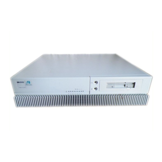
- Page 1 HP 4x Speed CD–ROM Disk Drive User’s Guide Workstation Systems Group Order No. A1658–90669 Edition E0895 Printed in U.S.A.
- Page 2 Hewlett-Packard Co. 1995 First Printing: August, 1995 UNIX is a registered trademark in the United States and other countries, licensed exclusively through X/Open Company Limited. NOTICE The information contained in this document is subject to change without notice. HEWLETT–PACKARD MAKES NO WARRANTY OF ANY KIND WITH REGARD TO THIS MATERIAL INCLUDING BUT NOT LIMITED TO THE IMPLIED WARRANTIES OF MERCHANTABILITY AND FITNESS FOR A PARTICULAR PURPOSE.
- Page 3 Contents Preface Chapter 1 Preparing for Installation...
- Page 4 Contents Chapter 2 Using your CD–ROM Drive Chapter 3 Maintenance and Troubleshooting...
- Page 5 Contents Appendix A Safety and Regulatory Statements Appendix B SCSI Connector Pinout...
- Page 6 Contents Figures Table...
- Page 7 Preface The HP 4x Speed CD–ROM Disc Drive User’s Guide describes how to install, configure, and use the HP 4x Speed CD–ROM Disc Drive with an HP 9000 Series 700 workstation. We’ve organized this guide as follows: Chapter 1 Describes the preparation procedures for installing the CD–ROM Disc Drive into the system.
-
Page 8: Installation Notice
The Owner’s Guide that came with your system HP-UX Installing Peripherals: HP 9000 Series 700 (B2355–90006) Using Your HP Workstation (A2615–90003) HP Visual User Environment User’s Guide (B1171–90061) System Administration Tasks HP 9000 Series 700 Computers (B2355–90040) Using HP-UX (B2910–90001) viii... -
Page 9: Revision History
The revision history for each edition of the manual is listed below: Edition Revision History E0895 First Printing. Problems, Questions, and Suggestions If you have any questions or problems with our hardware, software, or documentation, please contact either your HP Response Center or your local HP representative. Preface... -
Page 10: Documentation Conventions
Preface Documentation Conventions Unless otherwise noted in the text, this guide uses the following symbolic conventions: literal values Bold words or characters in formats and command descriptions represent commands that you must use literally. Pathnames are also in bold. user-supplied Italic words or characters in formats and command descriptions values represent values that you must supply. -
Page 11: Preparing For Installation
Chapter 1 Preparing for Installation This document describes the HP 4x Speed CD–ROM drive, and its installation, operation and maintenance. This chapter introduces the CD–ROM drive and contains the following information: General description of the CD–ROM drive Major features of the CD–ROM drive Preparing to install the CD–ROM drive... -
Page 12: General Description
Introduction General Description The HP 4x Speed CD–ROM drive is a random access, read–only, mass storage device that uses removable CD–ROM discs. The drive contains a semiconductor laser for reading data optically, and includes an embedded controller with a SCSI interface. - Page 13 Introduction Major Features of the CD–ROM Drive The CD–ROM drive offers the following features: 12cm/8cm discs 600 kB sustained transfer rate Supports 1X, 2X or 4X rotational modes 190 ms random access time 150 ms random seek time Built–in SCSI-2 controller Electric Load/Eject tray Emergency Eject Remote SCSI ID jumper block...
- Page 14 Introduction CD–ROM Drive Environmental Requirements The CD–ROM drive has the following environmental requirements: Temperature Operating Non–Operating Altitude Operating Non–Operating Humidity Operating @ 22 deg. C Non–Operating @ 60 deg. C 1–4 5 deg. C to 50 deg. C (41 deg. F to 122 deg. F) –10 deg.
- Page 15 The following illustration describes the physical specifications of the CD–ROM drive. Audio Out SCSI ID Mode Select SCSI Connector Power REAR BOTTOM Figure 1–2. HP 4x Speed CD–ROM Physical Specifications Terminator Socket LEFT AND RIGHT SIDES 4–M3 (TAP) 19.6 cm 4–M3 (TAP) 12 Location Mounting Screws Introduction 4.3 cm...
- Page 16 If any contents of your kit are missing, contact your sales representative. Minimum Requirements Minimum requirement for the HP–UX operating system is level 9.03 for the HP 4x Speed CD–ROM drive. NOTICE: You must use software patch PHSS_5764 under HP–UX 9.03, 9.05 and 9.07 to run SupportWave successfully.
- Page 17 Set the SCSI–2 Address The CD–ROM drive must have a unique SCSI–2 target address. The CD–ROM drive’s jumpers are set, at the factory, to the SCSI–2 default address of 2 as shown in Figure 1–3. You must also ensure that the operating mode jumpers are set for correct drive operation. We ship the drive with the operating mode jumpers set to operate correctly with your system.
-
Page 18: Address Jumpers
Introduction Address Jumpers To set the drive’s address, use the SCSI–2 address jumpers. Perform the following steps to set the drive’s address: Attach the static–grounding wrist strap by following the instructions on the package that contains the strap. Attach one end of the strap to the system chassis. Locate the address jumpers on the rear of the CD–ROM drive, as shown in Figure 1–3. - Page 19 SCSI–2 Terminators (must be removed) Jumpers Target Default Figure 1–3. SCSI–2 Address Settings Introduction Jumpers Target Default for /root (NOT recommended for CD–ROM drive) 1–9...
-
Page 20: Prepare The System
Before installing the drive, determine which SCSI–2 ID address settings are already being used on your system by completing the following substeps: If you are using HP–UX 9.05, enter the following at the prompt: After a few moments the ioscan utility lists all of the SCSI I/O devices it could find. - Page 21 After a few moments the ioscan utility lists all of the SCSI I/O devices it could find. The list appears similar to the following: H/W Path Class ============================================ ext_bus 8/0.0 target 8/0.0.0 disk 8/0.5 target 8/0.5.0 disk 8/0.6 target 8/0.6.0 disk 8/12 8/12/5...
- Page 22 You must have superuser privileges to use the /etc/shutdown command. If you do not have superuser privileges, contact your system administrator. If your workstation is part of a cluster, refer to the Managing Clusters of HP 9000 Computers manual for instructions on shutting down.
- Page 23 Single-Ended SCSI-2 Bus Configuration Constraints For the single-ended SCSI-2 bus, HP-UX supports only one of each type of removable- media disk drive (i.e., floppy disk, CD-ROM, or magneto-optical drives) and two of the same type tape devices (i.e., 4-mm DDS tape drives or 9-track tape drives), per SCSI bus.
- Page 24 Introduction Table 1–1. Single-Ended SCSI-2 Bus Configuration Constraints (per bus) Single-Ended SCSI-2 Devices Hard Disk Drives Floppy Disk Drives CD-ROM Drives 4-mm DDS Tape Drives 9-Track Tape Drives 650-MB Magneto-Optical Drives Magneto-Optical Autochangers (see notice below) 8-mm Cartridge Tape Subsystem 8 Serial Port Terminal Server Maximum Number of SCSI-2 Devices (per bus) NOTICE:...
- Page 25 SCSI-2 Bus Termination Guidelines There are certain guidelines to follow when terminating a SCSI-2 bus. These guidelines are: CAUTION: Unless the SCSI-2 bus is properly terminated, the bus will not operate. Terminators provide impedance matching on SCSI-2 bus signal lines. The last device connected to the SCSI-2 bus must be terminated with a SCSI-2 terminator.
- Page 26 If you are already at the boot–administration level (the level used to check the SCSI–2 IDs), you do not need to shut down before powering off. If you accidentally rebooted HP–UX while determining the address settings, see “Prepare the System,” earlier in this chapter, for instructions on shutting down HP–UX.
-
Page 27: Using Your Cd-Rom Drive
All SCSI devices can use the scsi device driver. To verify HP–UX system operation, see your System’s Owners Guide For more information on checking or reconfiguring the kernel for a device driver or file, see the System Administration Tasks Manual: HP 9000 Series 700 Computers. 2–1... - Page 28 Using Your CD–ROM Drive Your CD–ROM Drive Configuration Your HP–UX operating system comes with preconfigured device files and drivers. If you use these preconfigured device files and drivers, you won’t need to configure your CD–ROM drive with the operating system.
- Page 29 Controls and Features of the CD–ROM Drive Figure 2–1 shows the operating controls and features of the CD–ROM drive. Table 2–1 describes each of these controls and features. Headphone Jack Volume Control Busy Indicator Figure 2–1. CD–ROM Drive Controls and Features Using Your CD–ROM Drive CD–ROM Disc Loading Tray...
- Page 30 Using Your CD–ROM Drive Table 2–1. CD–ROM Drive Operating Controls and Features Control/Feature Purpose Eject Button Press the Eject Button to eject the disc tray. When the drive is in use, you must unmount the disc before ejecting it. Refer to the subsection “Unmounting a CD–ROM disc”...
-
Page 31: Using The Cd-Rom Drive
Using the CD–ROM Drive This section provides the following information about using the CD–ROM drive: Media description Disc tray description Loading and unloading the CD–ROM disc Mounting and unmounting a CD–ROM disc Reading the drive’s busy light Media Description CD–ROM discs are identical to audio compact discs (CDs), except that they store computer data. - Page 32 Using Your CD–ROM Drive Disc Tray Description This CD–ROM drive is mounted either horizontally or vertically. The disc tray has three disc holders which are used when the CD ROM drive is mounted vertically. The three disc holders are spring loaded to hold the disc in place. When the drive is mounted horizontally, the three disc holders are not used and are held out of the way by the three disc holder retainers.
- Page 33 Loading a CD–ROM Disc in a Horizontally Mounted Drive This CD–ROM drive has an automatic loading/ejecting feature. To load a disc in the CD–ROM drive, follow these steps: Check that the workstation is powered on. To open the Disc Tray, press and release the Load/Eject button on the CD–ROM drive.
- Page 34 Using Your CD–ROM Drive Unloading a CD–ROM Disc in a Horizontally Mounted Drive Perform the following steps to unload a disc from the CD–ROM drive: Press the eject button to eject the disc tray from the drive. If the drive is in use, you must unmount the disc to eject the disc tray.
- Page 35 Loading a CD–ROM Disc in a Vertically Mounted Drive Hold the disc with the label side to the left and place the edge of the disc onto disc holders A and B as shown in Figure 2–5. Press down gently against the spring tension of disc holders A and B and swing the top of the disc in until it is held by disc holder C.
- Page 36 Using Your CD–ROM Drive Unloading a CD–ROM Disc in a Vertically Mounted Drive Press the eject button to eject the disc tray from the drive. If the drive is in use, you must you must unmount the disc to eject the disc tray. The emergency eject feature allows you to eject the disc tray if the normal procedure fails.
- Page 37 Mounting a CD–ROM Disc To access your CD–ROM drive, you must mount a CD–ROM disc every time you insert it into the drive. CAUTION: Failure to mount a disc may cause a system error condition and may also require rebooting the system. Perform the following steps to mount a disc: Insert the CD–ROM disc into the disc tray, as described in “Inserting and Removing CD–ROM Discs Into and From the Disc Tray,”...
- Page 38 SCSI disk d# identifies the SCSI lun address (0, except for disk arrays) Device file names for CD_ROM drives at HP–UX 10.0 depend on the naming conven- tions of the system on which you are installing.
- Page 39 Use the following procedure to unmount a CD–ROM disc: Unmount the disc by entering the following: Using HP–UX 9.05 /etc/umount /dev/dsk/c201d2s0 Using HP–UX 10.0 /etc/umount /dev/dsk/c#t#d# Press the eject button on the CD–ROM drive. Remove the disc from the drive.
-
Page 40: Reading The Busy Light
Using Your CD–ROM Drive Reading the Busy Light The CD–ROM busy light shows the status of the drive during self test and during activity with the host system. The CD–ROM drive performs a self test when one of the following happens: You insert a disc into the drive. -
Page 41: Maintenance And Troubleshooting
Chapter 3 Maintenance and Troubleshooting This chapter provides the following information on maintenance and troubleshooting your CD–ROM drive: Caring for CD–ROM discs Troubleshooting Removal and Replacement Procedures 3–1... - Page 42 Caring for the CD–ROM Discs Use the following guidelines to help care for your CD–ROM discs. Use CD–ROM discs in a clean environment to prevent dust particles from scratching disc surfaces. Store CD–ROM discs in a cool, dry place to prevent moisture and heat damage. If the CD–ROM disc is dirty, wipe it with a soft cloth.
-
Page 43: Troubleshooting
It also explains how to run the Support Tool Manager or the Extended Self Test to verify your system. If you are experiencing difficulty booting the system, reconfiguring HP–UX, or using the CD–ROM drive, complete each of the following tasks, in the order they are presented, until you discover and correct the problem: Check the address settings of any single–ended SCSI–2 devices. - Page 44 A screen similar to the following appears: H/W Path Description ==================================== 1.0.0 graphics 2.0.1 scsi 2.0.1.2.0 disk 2.0.2 2.0.3 2.0.4 serial 2.0.5 serial 2.0.6 parallel 2.0.7 scsi 2.0.7.6.0 disk Look under the H/W Path heading for device paths beginning with the sequence 2.0.1. The sequence 2.0.1 denotes single–ended scsi controller.
- Page 45 If you are using HP–UX 10.0, enter the following at the prompt: /usr/sbin/ioscan –d sdisk RETURN After a few moments the ioscan utility lists all of the SCSI I/O devices it could find. The list appears similar to the following:...
- Page 46 You must have superuser privileges to use the /etc/shutdown command. If you do not have superuser privileges, contact your system administrator. If your workstation is part of a cluster, refer to the Managing Clusters of HP 9000 Computers manual for instructions on shutting down.
- Page 47 CAUTION: Do not power off your workstation without first shutting down HP–UX. Powering off with HP–UX still running could damage the data on the disks associated with your workstation. Remove the drive and check the jumpers, as described in Removal and Replacement Procedures at the end of this chapter.
- Page 48 Support Tools Manager so that you can verify your system operation. You can access the Support Tools Manager while in a terminal window. If you are using HP–VUE as your interface, you can also access the Support Tools Manager through the sys_admin directory.
- Page 49 To run SupportWave from either HP VUE or the HP–UX command line shell, perform the following steps: To invoke the command line interface, in a terminal window or command line shell, type the following at the prompt: # cstm RETURN...
- Page 50 NOTE: If a VUE login screen is currently displayed on the monitor, the test will wait until someone logs in the HP VUE on the graphics monitor to release the lock. The test stops if the Screen Saver times out, it runs again once the Screen is activated.
- Page 51 When you see the prompt shown above, type the following: >> RETURN The following messages and a graphics test window appear: Verification of (2/0/1.5.0) has completed. Result status – (Success). Verification of (2/0/1.6.0) has completed. Result status – (Success). Verification of (CPU) has completed. Result status – (Success). Verification of (FPU) has completed.
-
Page 52: Removal And Replacement Procedures
Removal and Replacement Procedures The Removal and Replacement Procedures for the CD–ROM Drive follow. CAUTION: Electrostatic charges can damage the integrated circuits on printed circuit boards. To prevent such damage from occurring, follow proper ESD precautions Field Replaceable Units The following components are authorized for field replacement. Description CD–ROM Drive Before performing the Removal and Replacement Procedures, observe the following... -
Page 53: Safety And Regulatory Statements
Appendix A Safety and Regulatory Statements This appendix contains the following safety and regulatory statements: Emissions regulations Emissions regulations compliance Acoustics Electrostatic discharge precautions Laser Safety Statement Warnings and cautions A–1... -
Page 54: Emissions Regulations
All HP Apollo nodes and peripherals have been tested and comply with these limits. The FCC regulations also require that computing devices used in the U.S. display the agency’s label and that the related documentation include the following statement:... -
Page 55: Emissions Regulations Compliance
Emissions Regulations Compliance Any third-party I/O device installed in HP Apollo system(s) must be in accordance with the requirements set forth in the preceding Emissions Regulations statements. In the event that a third-party noncompliant I/O device is installed, the customer assumes all responsibility and liability arising therefrom. -
Page 56: Electrostatic Discharge (Esd) Precautions
Safety and Regulatory Statements Electrostatic Discharge (ESD) Precautions Electrostatic charges can damage the integrated circuits on printed circuit boards. To pre- vent such damage from occurring, observe the following precautions during board un- packing and installation: Stand on a static-free mat. Wear a static strap to ensure that any accumulated electrostatic charge is dis- charged from your body to ground. -
Page 57: Laser Safety Statement (For U.s.a. Only)
LASERTURVALLISUUS LOUKAN 1 LASERLAITE KLASS 1 LASER APPARAT HP 4x Speed CD–ROM–lukulaite sisältää laitteensisäisen CD–ROM–yksikön, joka on laserlaite. Kyseinen CD–ROM–yksikkö on käyttäjän kannalta turvallinen luokan 1 laserlaite. Nor- maalissa käytössä yksikön suojakotelo estää lasersäteen pääsyn laitteen ulkopuolelle. CD–ROM–yksikön on tyyppihyväksynyt Suomessa laserturvallisuuden osalta Työminis- teriön työsuojeluosasto. - Page 58 Safety and Regulatory Statements IEC 825 Class 1 Laser Labels A–6 CLASS 1 LASER PRODUCT LASER KLASSE 1...
-
Page 59: Warnings And Cautions
Safety and Regulatory Statements Warnings and Cautions WARNING: Removing device cover may expose sharp edges in equipment chassis. To avoid injury, use care when installing customer add-on devices. WARNUNG: Das Entfernen der Geräteabdeckung legt die scharfen Kanten im Inneren des Gerätes frei. -
Page 60: Scsi Connector Pinouts
Appendix B SCSI Connector Pinouts This appendix provides a table listing the pinouts for the SCSI Connector on the CD–ROM drive. Table B–1. SCSI Connector Pinouts SIGNAL SIGNAL TERMPWR DB(0) DB(1) DB(2) –ATN DB(3) DB(4) –BSY DB(5) –ACK DB(6) –RST DB(7) –MSG DB(P) - Page 61 Order Number: A1658–90669 Edition E0895 Printed in U.S.A.