Table of Contents
Advertisement
Advertisement
Table of Contents

Related Manuals for Arris IPC1100


Summary of Contents for Arris IPC1100
- Page 1 Installation and Operations Manual IPC1100 Advanced IP Client Video Set-top...
- Page 2 ©ARRIS Enterprises, Inc. 2014 All rights reserved. No part of this publication may be reproduced in any form or by any means or used to make any derivative work (such as translation, transformation, or adaptation) without written permission from ARRIS Enterprises, Inc. (“ARRIS”).
-
Page 3: Safety And Compliance
WARNING - to reduce the risk of fire or electric shock, do not expose this apparatus to rain or moisture. The IPC1100 requires careful handling to avoid potential damage to its internal components. Be sure to follow these requirements during transportation and installation. -
Page 4: During Installation
FCC Declaration of Conformity ARRIS Enterprises, Inc., 101 Tournament Drive, Horsham, PA 19044, 1-215-323-1000, declares that the IPC1100 set-tops comply with 47 CFR Parts 2 and 15 of the FCC rules as a Class B digital device. - Page 5 Cet appareil numérique de la classe B est conforme à la norme NMB-003 du Canada. Caring for the Environment by Recycling When you see this symbol on a ARRIS product, do not dispose of the product with residential or commercial waste.
-
Page 6: Table Of Contents
Recommended Method for Access to OSD Diagnostics functionality ..........29 Optimizing the High-Definition Settings ...................... 30 Additional HDMI Settings ........................33 Additional Closed Caption Settings Menu ....................35 Graphics Overlaying the Video ........................36 Advanced IP Client Video Set-top IPC1100 • Installation and Operations Manual 365-095-24769 x.1 10/13... - Page 7 Figure 10 – IPC1100 Set-Top MAC Addresses ..................14 Figure 11 – Cabling to an HDTV ......................... 18 Figure 12 – Cabling to an HDTV for Audio ....................19 Advanced IP Client Video Set-top IPC1100 • Installation and Operations Manual 365-095-24769 x.1 10/13...
- Page 8 Figure 9 – Example General Status display (no error) ................40 Figure 10 Example Front Panel Display for Code Download status ............44 Figure 20 – Using a diplexer to bypass a line amplifier ................74 Advanced IP Client Video Set-top IPC1100 • Installation and Operations Manual 365-095-24769 x.1 10/13...
-
Page 9: Introduction
• Supports Over-The-Top IP content when not connected to a VMS1100 As with all ARRIS digital cable set-tops, the hardware features are enabled by core operating and third- party application software. IPC1100 Advanced IP Client Video Set-top • Installation and Operations Manual... -
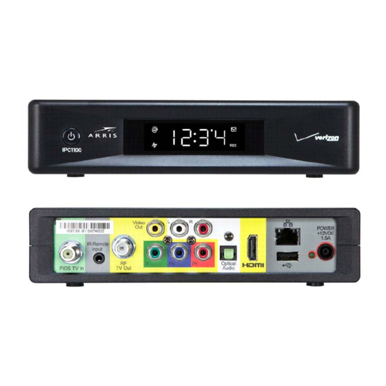
Page 10: Figure 1 - Ipc1100 Front And Rear Views
Introduction Figure 1 – IPC1100 Front and rear views IPC1100 Advanced IP Client Video Set-top • Installation and Operations Manual 365-095-24769 x.1 10/13... -
Page 11: Features
Introduction Features Tuners • The IPC1100 uses MoCA to communicate to the VMS1100 Gateway. Audio and video content, as well as entitlement messaging, are delivered over MoCA. Standard Audio/Video Features • Digital video scaling (picture in graphics) • Macrovision ®... -
Page 12: Table 1 - (Vms) Dvr Recording Time Guidelines
One rear Universal Serial Bus (USB) 2.0 port • 10/100 Mbps Ethernet Port (RJ-45) Standard Miscellaneous Features • Messaging capabilities • Digital diagnostics • Four-digit, seven-segment LED display IPC1100 Advanced IP Client Video Set-top • Installation and Operations Manual 365-095-24769 x.1 10/13... -
Page 13: Getting Help
Find technical documentation in the CustomerCare 360 Documentation Center (http://www.arrisi.com/cc360). Get release updates and download software from DigitalCM (digitalcm.arrisi.com). The ARRIS Training Learning Portal provides self-paced product training and course descriptions of instructor-led training classes at http://www.arris.com/support/training. In many cases training can be given at your location. -
Page 14: Overview
The Power button blinks when receiving a signal from the remote control. Figure 2 – IPC1100 front panel Table 2 – Front panel Label Description Power Display panel IPC1100 Advanced IP Client Video Set-top • Installation and Operations Manual 365-095-24769 x.1 10/13... -
Page 15: Rear Panel
Optical Audio (S/PDIF)* — Provides Dolby ® Digital 5.1 audio or PCM output HDMI — High-Definition TV (HDTV) connector USB 2.0 — Optional for future use Power LED Power cord connector IPC1100 Advanced IP Client Video Set-top • Installation and Operations Manual 365-095-24769 x.1 10/13... -
Page 16: System Overview
Overview System Overview This section introduces key concepts relevant to installing the ARRIS Whole Home IP Video Network CPE. It describes: • The passive optical network (PON) connecting the customer premises to the headend • The ARRIS Whole Home IP Video Network that you install at the customer premises •... -
Page 17: Whole Home Ip Video Customer Premises Network-Embedded Moca Bhr
A separate private virtual circuit carries telephone service over the PON. Whole Home IP Video Customer Premises Network—Embedded MoCA BHR The ARRIS Whole Home IP Video Network carries the following services over coaxial cable to the VMS: • Video QAM MPEG-2 encoded broadcast services over the full 50 to 864 MHz spectrum for MoCA 1.1 BHRs and the 1350 to 1675 MHz spectrum for MoCA 2.0 BHRs... -
Page 18: Figure 5 - Whole Home Ip Video Cpe Overview
IPC1100 advanced digital set-top supporting HDTV You must connect the BHR to an RF coaxial splitter connecting to the coaxial cable wall outlets in the other rooms in the customer’s premises. IPC1100 Advanced IP Client Video Set-top • Installation and Operations Manual 365-095-24769 x.1 10/13... -
Page 19: Moca
Each MoCA set-top requires an IP address for configuration and management, but does not require any other IP services. To minimize network IP address requirements, the MoCA uses the Link-Local IP address space. IPC1100 Advanced IP Client Video Set-top • Installation and Operations Manual 365-095-24769 x.1 10/13... -
Page 20: Multi-Room Dvr
• View a recorded program on the TVs connected to up to four media terminals Any connected IPC1100 can act as a media terminal. A household can support up to two VMS's with each VMS serving up to four clients. -
Page 21: Installation
Installation Installation Whole Home IP Video Network Installation This section provides instructions to connect the ARRIS Whole Home IP Video Network. Figure 9 – MoCA Set-Tops Note: Always be sure to follow all of the Important Safety Considerations. Before You Begin Before you move or change components on the subscriber’s entertainment system:... -
Page 22: During The Installation
Control. Be sure regular and VoD channels display. Optimize the high-definition settings. Checking the Home Coaxial Network Topology This section assumes you are networking two or more IPC set-tops. Before you install the ARRIS Whole Home IP Video Network hardware: 1. Create a table listing: ο... -
Page 23: Video Connection Options
To determine the available video inputs on the TV, check the manual supplied with the TV or the TV itself. The IPC1100 offers the following video outputs: IPC1100 Advanced IP Client Video Set-top • Installation and Operations Manual 365-095-24769 x.1 10/13... -
Page 24: Audio Connection Options
(composite) only video (video) output. SDTV If the TV only has a coaxial RF input, connect it to the IPC1100 RF out only connector. Audio Connection Options When connecting to a home theater receiver, depending on its inputs, you can use the following... -
Page 25: Installation Overview
If the TV has no HDMI input but does have a DVI input, connect a DVI-to-HDMI adapter or cable to the HDMI out connector on the IPC1100 set-top, and the DVI-HDTV connector on your TV. Note: A separate audio connection will be needed. -
Page 26: Cabling To An Hdtv For Video
For the best possible HDTV video quality: 1. If the TV has an HDMI input, connect it to the IPC1100 HDMI output. If the TV has a DVI input, you can connect it to the IPC1100 HDMI output using an HDMI-to-DVI converter cable or adapter. -
Page 27: Cabling To An Hdtv For Audio
Installation Cabling to an HDTV for Audio Figure 12 – Cabling to an HDTV for Audio IPC1100 Advanced IP Client Video Set-top • Installation and Operations Manual 365-095-24769 x.1 10/13... -
Page 28: Cabling To A High-Definition Tv And An A/V Receiver For Video
Figure 13 – Cabling to an HDTV and A/V Receiver for Video Note: If the A/V receiver includes an HDMI input & output, the IPC1100 HDMI output can be connected directly to the A/V receiver. Because HDMI provides both video and audio output, no additional audio connections to the A/V Receiver and TV are required. -
Page 29: Cabling To A High-Definition Tv And An A/V Receiver For Audio
Figure 14 – Cabling to an HDTV and A/V Receiver Note: If the A/V receiver includes an HDMI input & output, the IPC1100 HDMI output can be connected directly to the A/V receiver. Because HDMI provides both video and audio output, no additional audio connections to the A/V Receiver and TV are required. -
Page 30: Cabling To A Standard-Definition Tv
Installation Cabling to a Standard-Definition TV Figure 15 – Cabling to a Standard Definition stereo TV IPC1100 Advanced IP Client Video Set-top • Installation and Operations Manual 365-095-24769 x.1 10/13... -
Page 31: Data Device Connections
Data Device Connections The IPC1100 rear panel provides the following data ports: Port type Description USB 2.0 Optional for future use Ethernet 10/100 Mbps RJ-45 port IPC1100 Advanced IP Client Video Set-top • Installation and Operations Manual 365-095-24769 x.1 10/13... -
Page 32: Autoprovisioning
IPC. The IPC can be connected to the BHR through MoCA or Ethernet. 1. Connect the power cord to an AC outlet. Do not power up the IPC1100 until the network and TV connections are made and VMS is provisioned. -
Page 33: Figure 16 - Welcome-Start Activation Screen
Installation Figure 16 – Welcome-Start Activation Screen. Figure 17 – Overlay screen during AP in an error state. Press A to switch to detail screens. IPC1100 Advanced IP Client Video Set-top • Installation and Operations Manual 365-095-24769 x.1 10/13... -
Page 34: Figure 18 - Health Checks Begun
Installation Figure 18 – Health checks begun. Figure 19 – Example error screen. IPC1100 Advanced IP Client Video Set-top • Installation and Operations Manual 365-095-24769 x.1 10/13... -
Page 35: Figure 20 - Step 2 Software Download
Installation Figure 20 – Step 2 Software Download Figure 21 – Step 3-Activation Screen IPC1100 Advanced IP Client Video Set-top • Installation and Operations Manual 365-095-24769 x.1 10/13... -
Page 36: Registration With The Media Server
IPC. Verifying the MoCA Network To verify that the nodes are connected, check the rates on the Connected Home Status diagnostic (see Troubleshooting). IPC1100 Advanced IP Client Video Set-top • Installation and Operations Manual 365-095-24769 x.1 10/13... -
Page 37: Operational Check For The Remote Control
From the BUI Menu, the user can select and navigate to User Setting Menu. The alternate method of accessing the diagnostics is to power on the IPC1100 and then immediately press the select key twice (or the OK key) of the remote. -
Page 38: Optimizing The High-Definition Settings
1. Connect the IPC1100 set-top to other home entertainment devices. 2. Plug the IPC1100 set-top into a power outlet. 3. Ensure that the IPC1100 has completed the auto provisioning process and has connectivity to a VMS through the home network. -
Page 39: Figure 24 - User Settings
Use the front panel display to adjust the settings as described in “There is no video on the TV screen” in the Troubleshooting section. IPC1100 Advanced IP Client Video Set-top • Installation and Operations Manual 365-095-24769 x.1 10/13... - Page 40 Some televisions may only support certain video formats. Please consult your television’s user manual for more information on format compatibility. The IPC1100 set-top can detect when the HDMI connection is in use. If you are not using the HDMI connection on the IPC1100 set-top, the HDMI/YPbPr Output setting will display as YPbPr Output in the User Settings Menu.
-
Page 41: Additional Hdmi Settings
DVI — The IPC1100 is optimized to work with a DVI television or display device (connected via an HDMI-to-DVI adapter). The Color Space setting allows you to adjust the color space used by the IPC1100 to Color Space generate the video signals on the HDMI output. By default, this option is set to YCC 4:4:4. - Page 42 Auto — The IPC1100 will automatically delay the audio signal on the HDMI output by the amount of time requested by the connected HDMI device. Manual — The IPC1100 will delay the audio signal on the HDMI output by the amount of time selected for the Lip Sync Delay setting.
-
Page 43: Additional Closed Caption Settings Menu
Setting Description Service Sets the service used by IPC1100 to render (draw) the closed captions: Selection Analog — This setting affects closed captions for analog and digital standard definition services. Available options are: CC1, CC2, CC3, CC4, T1, T2, T3, or T4. The default setting is CC1. -
Page 44: Graphics Overlaying The Video
The IPC1100 can generate graphics that overlay the video programming or fill the entire television screen. Common examples include on-screen menus (such as the User Setting menu), closed captions, and IPG. The IPC1100 overlays these graphics whenever you open a menu, enable closed captions, or scroll through a program grid. -
Page 45: Diagnostics
Using the Diagnostics To use the diagnostics: 1. Ensure that the IPC1100 is installed with the current version of software and that it is connected to an AC outlet. There are two methods to Access User Setting to optimize the output settings: a. -
Page 46: Figure 8 - Example Of The Front Panel Display For The Main Menu
3. Press channel ▲, channel ▼, cursor ▲, or cursor ▼ to select 01 through 17. 4. Press cursor ◄, cursor ►, select or enter to execute the selected diagnostic. 5. Select Exit from the Remote or press Power to exit. IPC1100 Advanced IP Client Video Set-top • Installation and Operations Manual 365-095-24769 x.1 10/13... -
Page 47: General Status
Note: Grayed out menu items do not pertain to the IP Client and therefore are not selectable from the Main Diagnostics menu. IPC1100 Advanced IP Client Video Set-top • Installation and Operations Manual 365-095-24769 x.1 10/13... -
Page 48: Figure 9 - Example General Status Display (No Error)
Error Code Description E 00 No error EP01 Not connected EP03 DRAM error EP04 SRAM error EP07 ROM verification failure EP08 RAM test failure IPC1100 Advanced IP Client Video Set-top • Installation and Operations Manual 365-095-24769 x.1 10/13... - Page 49 Indicates if the device received the Client Connected message from the headend. State Client Activation Indicates if the devices receive the Activation message from the headend. Status IPC1100 Advanced IP Client Video Set-top • Installation and Operations Manual 365-095-24769 x.1 10/13...
-
Page 50: Unit Address/Security
The front panel will display the unit address of the device when the Address/Security screen is displayed, if the device supports a unit address. See the following examples: IPC1100 Advanced IP Client Video Set-top • Installation and Operations Manual 365-095-24769 x.1 10/13... -
Page 51: Code Module
Diagnostics 03 Code Module IPC1100 Advanced IP Client Video Set-top • Installation and Operations Manual 365-095-24769 x.1 10/13... -
Page 52: Figure 10 Example Front Panel Display For Code Download Status
Identifies the product configured Group. Region ID Identifies the product configured Region. Primary Server Primary method for Code download. Options are: Download Path "Multicast" "Unicast" "N/A" ‘Undefined” IPC1100 Advanced IP Client Video Set-top • Installation and Operations Manual 365-095-24769 x.1 10/13... - Page 53 MRL file, if available. Next MRL IPMC Join The scheduled data and time when the product is expected joined the MRL Time multicast, if available. IPC1100 Advanced IP Client Video Set-top • Installation and Operations Manual 365-095-24769 x.1 10/13...
- Page 54 The IP address of the server from which the object is downloaded. In case of Address Multicast, it represents the Source IP. Current DL Server The type of download server currently being used. Options are: Type "Multicast" "Unicast" "N/A" IPC1100 Advanced IP Client Video Set-top • Installation and Operations Manual 365-095-24769 x.1 10/13...
- Page 55 IP multicast. Object PID PID for the object in the DSMCC carousel; the number of objects will increase the number of pages displayed as necessary IPC1100 Advanced IP Client Video Set-top • Installation and Operations Manual 365-095-24769 x.1 10/13...
-
Page 56: Http Adaptive Video Information
This parameter is the transfer rate - the bit rate of the last chunk or segment it pulled Segment down from the server. Bitrate Playlist Name This playlist contains the variant playlist names for different bit rates. IPC1100 Advanced IP Client Video Set-top • Installation and Operations Manual 365-095-24769 x.1 10/13... - Page 57 "SecureMedia" "Vz AES-128" "N/A" Source IP IP address of streamer server Source Port The port of streamer server that is being used for the OTT streaming. IPC1100 Advanced IP Client Video Set-top • Installation and Operations Manual 365-095-24769 x.1 10/13...
-
Page 58: In Home Streaming
Number of packets in the client buffer. Count Platform Media Player Status of the media player in the client device. Values are: Event Status "Playing" "Paused" "Stopped" "Trick Play" IPC1100 Advanced IP Client Video Set-top • Installation and Operations Manual 365-095-24769 x.1 10/13... -
Page 59: Audio / Video Status
The Video Mute indicates if any of the video outputs have been muted by the software, for example, selectable output control. Input The input source list information on Audio Mode, VP Lock, and Input Format. Source IPC1100 Advanced IP Client Video Set-top • Installation and Operations Manual 365-095-24769 x.1 10/13... - Page 60 The input format includes the aspect ratio (4:3 or 16:9), the screen pixel size Format (nnnnXnnnn), pixel display (‘i’ for interlaced, ‘p’ for progressive), and frames per second (24, 25, 30, 60). IPC1100 Advanced IP Client Video Set-top • Installation and Operations Manual 365-095-24769 x.1 10/13...
-
Page 61: Memory Configuration
The total process load on the CPU. CPU Load Average CPU load percentage per process. % CPU and Memory Per RAM Memory Used Per Process (scroll down for more processes). Process IPC1100 Advanced IP Client Video Set-top • Installation and Operations Manual 365-095-24769 x.1 10/13... -
Page 62: Interface / Port Status
Diagnostics 09 Interface / Port Status IPC1100 Advanced IP Client Video Set-top • Installation and Operations Manual 365-095-24769 x.1 10/13... - Page 63 Indicates if closed captions have been turned off or on. The front panel display Caption indicates the status of the closed captions. Defaults to No. Options are Yes and No. Enabled IPC1100 Advanced IP Client Video Set-top • Installation and Operations Manual 365-095-24769 x.1 10/13...
- Page 64 Indicates the format of the audio as PCM, DD, or AAC Output HDMI Audio Indicates the audio rate, for example, 32, 44.1, 48. Or 96 kHz Rate IPC1100 Advanced IP Client Video Set-top • Installation and Operations Manual 365-095-24769 x.1 10/13...
-
Page 65: Current Sessions
VMS that will allow connected clients to continue TV viewing. NOTE: An OTT session has a limited/scaled back channel map so not all channels will be available for the IP clients. IPC1100 Advanced IP Client Video Set-top • Installation and Operations Manual 365-095-24769 x.1 10/13... -
Page 66: Connected Home
Status TRUE = Active FALSE = Inactive Ethernet Number of times Ethernet connectivity was lost since last boot. Connectivity Loss Count Additional Selectable information screens. Information IPC1100 Advanced IP Client Video Set-top • Installation and Operations Manual 365-095-24769 x.1 10/13... - Page 67 Network Coordinator Indication Indicates which device is the MoCA Network Coordinator. TRUE = Device is network coordinator FALSE = Device is not network coordinator IPC1100 Advanced IP Client Video Set-top • Installation and Operations Manual 365-095-24769 x.1 10/13...
- Page 68 Fr — The node received significant packet errors caused by thermal noise or interfering signals. Pw — There is insufficient power at the node. IPC1100 Advanced IP Client Video Set-top • Installation and Operations Manual 365-095-24769 x.1 10/13...
- Page 69 MoCA Rx Power The RF receive power level at the STB being polled expressed in dBmV for the link between the connected node and the STB being polled. IPC1100 Advanced IP Client Video Set-top • Installation and Operations Manual 365-095-24769 x.1 10/13...
- Page 70 Window will be considered as t minutes in the past upto the current time. Uncorrectable MoCA received uncorrectable packet count for each direct link between the local Packet Count and each MoCA node on the MoCA network, if available. IPC1100 Advanced IP Client Video Set-top • Installation and Operations Manual 365-095-24769 x.1 10/13...
- Page 71 The priority code point setting of a particular traffic type as defined by IEEE 802.1p. The possible values are 0-7. N/A is used to indicate that Priority is Not Assigned. DSCP Mark DSCP value to be used. IPC1100 Advanced IP Client Video Set-top • Installation and Operations Manual 365-095-24769 x.1 10/13...
- Page 72 The link speed expressed in Mbps. The values are 10, 100 and 1000. Link Duplex This parameter indicates whether Duplex mode is enabled (after autonegotiation) for the link. TRUE = Enabled FALSE = Disabled IPC1100 Advanced IP Client Video Set-top • Installation and Operations Manual 365-095-24769 x.1 10/13...
- Page 73 Description Discovered VMS List of IP addresses of the VMS’s discovered in the home network. Additional List pages will be displayed as needed to display VMS’s. IPC1100 Advanced IP Client Video Set-top • Installation and Operations Manual 365-095-24769 x.1 10/13...
- Page 74 IP address. BHR DNS 1 IP Address IP Address of the DNS. BHR DNS 2 IP Address IP Address of a second DNS server, if detected. IPC1100 Advanced IP Client Video Set-top • Installation and Operations Manual 365-095-24769 x.1 10/13...
- Page 75 The priority code point setting of a particular traffic type as defined by IEEE 802.1p. The possible values are 0-7. N/A is used to indicate that Priority is Not Assigned. DSCP Mark DSCP value to be used. IPC1100 Advanced IP Client Video Set-top • Installation and Operations Manual 365-095-24769 x.1 10/13...
-
Page 76: Wan Status
Diagnostics 16 WAN Status Field Description Failed Inform Count The number of failed Inform attempts since the last successful Inform. IPC1100 Advanced IP Client Video Set-top • Installation and Operations Manual 365-095-24769 x.1 10/13... -
Page 77: Keypad Status
This diagnostic verifies the functionality of the front panel indicators and the front-panel keypad. Each highlighted character corresponds with a front-panel key press. Field Description Key Code Indicates the keycode of Front Panel Key or associated IR Keypress. IPC1100 Advanced IP Client Video Set-top • Installation and Operations Manual 365-095-24769 x.1 10/13... -
Page 78: Troubleshooting
Try again in a few minutes. • Verify that the AC power cord is connected to the IPC1100 set-top and an AC outlet. Unplug the IPC1100 set-top from the AC outlet, plug it back in, and then press the POWER button. - Page 79 4:3 video). • If the IPC1100 is connected to a widescreen TV, verify that the TV TYPE is set to 16:9 in the User Settings menu. Many HD programs are broadcast in pillar-box format with black bars to the left and right of the picture.
- Page 80 • Set the TV TYPE to 4:3 Pan-Scan. This enables the IPC1100 to remove the black bars above and below the picture when possible. Some SD programs are broadcast in the letterbox format with black bars above and below the picture.
-
Page 81: Ip Network Issues
See “Bypassing” an Amplifier below. As long as the light on the BHR continues to flash, repeat this procedure. If you make any changes, repeat all tests. IPC1100 Advanced IP Client Video Set-top • Installation and Operations Manual 365-095-24769 x.1 10/13... -
Page 82: Bypassing An Amplifier
Root Node Existing Line Amp Install Line Amp between the Low-Pass ports on the Diplexers Figure 28 – Using a diplexer to bypass a line amplifier IPC1100 Advanced IP Client Video Set-top • Installation and Operations Manual 365-095-24769 x.1 10/13... - Page 83 ARRIS Enterprises, Inc. 3871 Lakefield Drive Suwanee, GA 30024 www.arrisi.com 365-095-24769 x.1 10/14...
Need help?
Do you have a question about the IPC1100 and is the answer not in the manual?
Questions and answers