Table of Contents
Advertisement
ALINCO, INC.
Yodoyabashi Dai-bldg 13F
4-4-9 Koraibashi, Chuo-ku, Osaka 541-0043 Japan
Phone: +81-6-7636-2362 Fax: +81-6-6208-3802
http://www.alinco.com
E-mail:export@alinco.co.jp
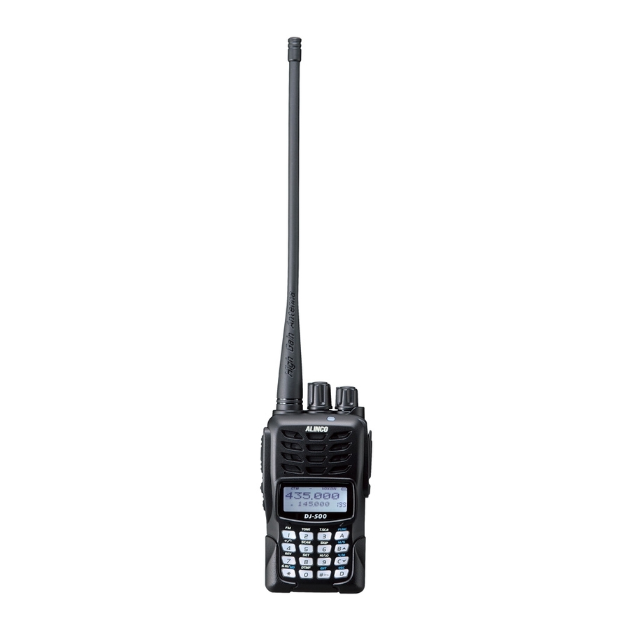
VHF/UHF FM amateur transceiver
144.000~145.995MHz / 430.000~439.995MHz
All EU and EFTA member states. Operator
license is required.
Copyright Alinco, lnc. PS0800/FNEG-EF
Printed in China
Advertisement
Table of Contents

Related Manuals for Alinco DJ-500


Summary of Contents for Alinco DJ-500
- Page 1 ALINCO, INC. Yodoyabashi Dai-bldg 13F 4-4-9 Koraibashi, Chuo-ku, Osaka 541-0043 Japan Phone: +81-6-7636-2362 Fax: +81-6-6208-3802 http://www.alinco.com E-mail:export@alinco.co.jp VHF/UHF FM amateur transceiver 144.000~145.995MHz / 430.000~439.995MHz All EU and EFTA member states. Operator license is required. Copyright Alinco, lnc. PS0800/FNEG-EF Printed in China...
-
Page 2: Instruction Manual
VHF/UHF FM Transceiver DJ-500 Instruction Manual Thank you for purchasing your new Alinco transceiver. Please read this manual carefully before using the product to ensure full performance, and keep this manual for future reference as it contains information on after-sales service. -
Page 3: Before Transmitting
Introduction Thank you very much for purchasing this excellent Alinco transceiver. Our products are ranked among the finest in the world. This radio has been manufactured with state of the art technology and it has been tested carefully at our factory. It is designed to operate to your satisfaction for many years under normal use. - Page 4 Alinco accessories and the radio has not been disassembled by the customer. The factory has tested and made the equipment compatible to IP54 certification during engineering.
- Page 5 Features ■ Output power selectable 5W/2.5W/1W ■ 200 PC-programmable channels ■ Li-Ion battery pack and stand-charger as standard accessories ■ Alphanumeric name tags ■ FM broadcast 76-108MHz receiver built-in ■ Selectable Battery-save parameters ■ Busy Channel Lockout ■ CTCSS/DCS Encode/Decode, DTMF, 5-Tone ■...
- Page 6 Information in this document is subject to change without notice or obligation. All brand names and trademarks are the property of their respective owners. Alinco cannot be liable for pictorial or typographical inaccuracies. Some parts, options and/or accessories are unavailable in certain areas. Changes or modifications not expressly approved by the party responsible for compliance could void the user's authority to operate the equipment.
- Page 7 CE Conformity Information This device is in compliance with the essential requirements of R&TTE Directive 1999/5/EC. A copy of the certificate by the notified body can be reviewed at http://www.alinco.com/usa.html. DJ-500E VHF/UHF FM amateur radio handheld transceiver 144.000~145.995MHz, 430.000~439.995MHz...
-
Page 8: Environment And Condition Of Use
Alert Environment and condition of use Use of this product may be prohibited or illegal outside of your country. Be informed in advance when you travel. It is recommended that you check local traffic regulations regarding the use of a radio equipment while driving. -
Page 9: Handling This Product
The manufacturer declines any responsibilities against loss of life and property due to a failure of this product when used with or as a part of a device made by third parties. Use of third party accessory may result in damage to this product. It will void our warranty for repair. Handling this product Be sure to reduce the audio output level to minimum before using an earphone or a headset. -
Page 10: In Case Of Emergency
Securely plug the adapter into the wall outlet. Insecure installation may result in short-circuit, electronic shock and/or fire. Do not use the adapter if the plug or socket contacts are dirty. Overheating and/or short-circuiting may result in fire, electric shock and/or damage to the product. In case of emergency In case of the following situation(s), please turn off the product, switch off the source of power, then remove or unplug the power-cord. -
Page 11: About Transceiver
Alert Environment and condition of use Do not use the product in proximity to a TV or a radio. It may cause interference or receive interference. Do not install in a humid, dusty or insufficiently ventilated place. It may result in electric shock, fire and/or malfunction. - Page 12 Use a clean, dry cloth to wipe off dirt and condensation from the surface of the product. Never use thinner or benzene for cleaning. Check with your local waste officials for details on recycling or proper disposal of the electronics product, battery-packs and accessories in your area.
-
Page 13: Table Of Contents
TABLE OF CONTENTS STANDARD ACCESSORIES ................................01 Standard Accessories ..................................01 BATTERY INFORMATION ................................. 02 Charging Operation ....................................02 Battery Charger Type ................................... 02 Notice for Charging Battery ................................02 How to Charge the battery pack ..............................04 How to Store the Battery .................................. - Page 14 TABLE OF CONTENTS Channel Input by Keypad .................................. 15 Monitor / Squelch Off ................................... 15 Receiving ........................................15 Transmitting ......................................16 Alarm ..........................................16 Side Key [PF1] function instruction ............................... 16 Side key [PF2] function instruction ..............................17 Channel Edit ......................................
- Page 15 TABLE OF CONTENTS CTCSS/DCS Encode / Decode Synchronous Setup ......................26 Choose To Transmit 5TONE ................................27 Add or Cancel DTMF, 5TONE Sgnaling ............................. 27 Signaling Combination ..................................28 Frequency Step ...................................... 28 Wide/ Narrow FM Mode ..................................29 Frequency Reverse ....................................
- Page 16 TABLE OF CONTENTS Tone Pulse Frequency ..................................39 Battery Save ......................................39 FM radio ......................................... 40 SET MODE OPERATIONS ................................41 Display Mode ....................................... 41 Reset ........................................41 AUXILIARY FUNCTIONS ................................42 Cable Cloning ...................................... 42 DEFAULT SETTINGS ..................................43 OPTIONAL ACCESSORIES ................................
-
Page 17: Standard Accessories
STANDARD ACCESSORIES Standard Accessories Antenna Battery Charger AC Adaptor Belt Clip Instruction Hand Strap Manual NOTE: Accessories may differ depending on the version you have purchased. Please contact your local dealer for details of standard accessories and the warranty-policy before purchase. -
Page 18: Battery Information
Battery Charger Type Please use Alinco's designated charger, other models may cause explosion. After installing the battery, when the radio displays low battery, please charge the battery. - Page 19 BATTERY INFORMATION Caution • Risk of explosion, generation of heat or leak of chemicals inside if the battery is replaced by an incorrect type or reverse polarity. Use always the recommended types of batteries in this manual only. • The battery pack isn't fully charged when shipped. It must be charged before use. •...
-
Page 20: How To Charge The Battery Pack
BATTERY INFORMATION How to Charge the battery pack 1.Plug the AC adaptor into the AC outlet, then plug into the DC jack, the indicator lights orange for 1 second and goes out---waits to charge. 2.Slide the battery or transceiver with battery into the charger;... - Page 21 BATTERY INFORMATION 6. LED Indicator: self-examine Charge Fully STATUS (No battery) Pre-charging Trouble when power on normally Charged Orange Red blinks for 5 Red blinks None Green (for 1 second) minutes alternatively NOTE: ▲ Trouble means battery heating, short-circuit or charger malfunction. Remove the battery pack from the charger immediately and contact to your local dealer for services.
-
Page 22: How To Store The Battery
BATTERY INFORMATION How to Store the Battery 1.The battery should be kept in the status of 50% discharge when storing. 2.It should be kept in cool, dry environment and remove it from the transceiver. 3.Keep away from source of heat and direct sunlight. NOTE: Incorrect storage will damage both the battery pack and the radio. -
Page 23: Installation & Connection
INSTALLATION & CONNECTION Installing / Removing the Li-ion Battery 1.Match the three grooves of the battery pack with the corresponding guides on the back of the transceiver, then push it. 2.Press the battery and transceiver firmly together until the release latch on the top of the transceiver locks. After hearing a "click"... -
Page 24: Installing / Removing The Belt Clip
INSTALLATION & CONNECTION Installing / Removing the Belt Clip Installing the Belt Clip: 1. Put the belt clip on the back of the unit, and the screw clockwise until it stops. 2. Confirm that the belt clip is securely attached. * Tighten up the screw occasionally. -
Page 25: Installing The Hand Strap
INSTALLATION & CONNECTION NOTE: 1.To keep the radio dust and splash resistant, the cover must be closed properly with the original supplied cover. 2.The radio is not dust and splash resistant while using the optional accessory risking that the water may penetrate inside through the plug. -
Page 26: Getting Acquainted
GETTING ACQUAINTED LCD Display Following are the meaning of the icons and signs shown on the display. Frequency VOX Function Reverse Offset direction Scan Skip Narrow band Optional Signaling CTCSS Battery Capacity FUNC Icon Main Channel Function Menu Serial Sub-channel No. -
Page 27: Front Panel
GETTING ACQUAINTED Front Panel Main dial Antenna Power / Volume Switch TX/RX indicator, Main RX is Green, Sub RX is Blue, TX is Red Speaker Microphone A key/Function key C key/Down key/Main/Sub Exchange key Numeric keys C key/Down key/Channel/ VFO Exchange key D key, Exit key NOTE: Please do not close the microphone hole. -
Page 28: Side Panel
GETTING ACQUAINTED Side Panel PTT key Accessory and PC programming port PF1 key (1 Primary Function key) PF2 key (2 Primary Function key) Belt Clip Battery Left Panel Right Panel... -
Page 29: Basic Operations
BASIC OPERATIONS Power On and off Turn【POWER】/【VOLUME】dial clockwise to power on. Turn it counterclockwise to power off. Adjusting Audio output level Press and hold 【PF2】 key to monitor white noise to refer to the current audio level. Turn【POWER】/【VOLUME】dial clockwise to increase the audio level, counterclockwise to decrease. -
Page 30: Switch Between Main Band And Sub Band
BASIC OPERATIONS Switch between Main band and Sub band Press key to switch between Main band and Sub band. Switch between Channel mode and VFO mode Press key to switch between channel mode or frequency mode(VFO). Change Frequency / Channel Through Main Dial In VFO mode, you can change the current frequency to desired one through main dial;... -
Page 31: Channel Input By Keypad
BASIC OPERATIONS Example: To enter 435.0125, press [4][3][5][0][1][2] then 5 appears and sets automatically. To enter 435.100, press [4][3][5][1][0][0]. By pressing the last [0], a dot appears after the MHz unit and the frequency is set. When an invalid numbers are entered, the display will return to the current state and an error beep sounds. -
Page 32: Transmitting
BASIC OPERATIONS NOTE: Please be aware of the squelch level and selective-calling settings such as CTCSS and DCS as you may risk not hearing the receiving signal. Transmitting 1. Select the frequency by using the dial or keypad. 2. Press the PTT key. The red TX indicator turns on while transmitting. 3. -
Page 33: Side Key [Pf2] Function Instruction
BASIC OPERATIONS 2.In receiving mode, press and hold to alarm.(you can shut off this function by software) 3.In transmitting mode, press to transmitting selected Tone-pulse signaling. 4.Press this key to power on transceiver, and get into wire cloning mode. NOTE: The tone pulse frequency can be set to 1750Hz, 1450Hz, 1000Hz or 2100Hz in programming software. Side key [PF2] function Monitor function (squelch off or momentary off per preprogramming). -
Page 34: Delete Channel
BASIC OPERATIONS Delete channel 1.In Standby state, after pressing key, the top left corner of LCD displays " ", then press , the channel number twinkling means getting into store/delete channel mode. 2.Turn selector knob to select the channel which you want to delete. 3.Press key, and hold key for 2 seconds, the frequency disappear with in two "beep"... -
Page 35: Advanced Operations
ADVANCED OPERATIONS FM Radio Receiver 1. In standby state, after pressing key, while icon is displayed on the top left corner, then press key again, LCD displays "FM" icon and "FM ON", FM radio function is on. 2. While "FM ON" is indicated on the display, press key to turn on/off FM radio function, FM radio is on when LCD displays "FM ON", FM radio is off when LCD displays "FM OFF". -
Page 36: Ctcss/Dcs Scan
ADVANCED OPERATIONS CTCSS/DCS Scan After pressing key, the top left corner of LCD displays " ", then press to enter CTCSS / DCS scan. When signaling scanned matches the setting of the transceiver, stop for 15 seconds then scan again. Press any keys except to exit scanning. -
Page 37: Scan Channel Skip
ADVANCED OPERATIONS explained later. Default is timed and resumes scanning after 5 seconds regardless of receiving state. 1.Frequency Scan In VFO mode, it scans in accordance with the channel step. Press any key except keys to stop scanning. 2.Channel Scan In channel mode, it scans in accordance with preprogrammed channels. -
Page 38: Frequency Reverse
ADVANCED OPERATIONS Frequency Reverse In standby state, press key, the top left corner of LCD displays " " icon, then press to set the current channel to Reverse function, Repeat the operations to cancel channel Reverse function. 1. When LCD displays "R" icon, it means current arrow directed channel open the frequency reverse function, the TX frequency and RX frequency is interchanged, if CTCSS/DCS signaling is set, it will also interchange. -
Page 39: Dtmf Code Searching And Setup
ADVANCED OPERATIONS NOTE: During timing, press key to stop timing and displays current data, press this key again to clear timer. DTMF Code Searching And Setup After pressing key, the top left corner of LCD displays " " then press key, it displays the current DTMF group. -
Page 40: Switch Between Dual Mode And Single Mode
ADVANCED OPERATIONS Switch between Dual mode and Single mode In order to reduce the working main channel suffer from sub-channel interference, can quickly close the sub-channel. 1. In standby mode, press the key, the transceiver shows main channel and close the sub-channel. -
Page 41: Ctcss/Dcs Encode Setup
ADVANCED OPERATIONS CTCSS/DCS Encode Setup 1.After pressing A key, the top left corner of LCD displays " " then press key. 2.Press key to choose menu 01 and display "T-CDC". 3.Press key to choose CTCSS, DSC or OFF. When DCS is selected, press key to choose positive or inverse code. -
Page 42: Ctcss/Dcs Encode / Decode Synchronous Setup
ADVANCED OPERATIONS 4.Turn main dial to choose the desired CTCSS / DCS decodeing tone. See appendix for details of available tones. 5.Press key or key to confirm and exit. Note: You may set the encoding and decoding tones separately. CTCSS/DCS Encode / Decode Synchronous Setup This function is for adjusting CTCSS/DCS encode/decode synchronous. -
Page 43: Choose To Transmit 5Tone
ADVANCED OPERATIONS Choose To Transmit 5TONE By preprogramming the 2-Tone setting in advance, you may select the tone and transmit it. 1.After pressing key, the top left corner of LCD displays " " then press key. 2.Press key to choose menu 04 and display "5TONE ". 3.Turn main dial to choose the desired 5-Tone signal. -
Page 44: Signaling Combination
ADVANCED OPERATIONS Signaling Combination You may combine the signaling functions of different system. 1.After pressing key, the top left corner of LCD displays " " then press key. 2.Press key to choose menu 06 and display "SIGNAL". 3.Turn main dial to choose the desired signaling combinations mentioned below. SQ: Hear all communications regardless of the signaling tones. -
Page 45: Wide/ Narrow Fm Mode
ADVANCED OPERATIONS Wide/ Narrow FM Mode 1.After pressing key, the top left corner of LCD displays " " then press key. 2.Press key to choose menu 08 and display " W/N". 3.Turn main dial to choose the desired bandwidth frequnecy. Available parameters are 12.5(narrow) and 25KHz(wide). -
Page 46: Offset Frequency
ADVANCED OPERATIONS 3.Turn main dial to choose the desired parameter. TX=RX: talk around enables OFF: talk around disables 4: Press key or key to confirm end exit. Offset Frequency 1.After pressing key, the top left corner of LCD displays " "... -
Page 47: Busy Channel Lockout
ADVANCED OPERATIONS Busy Channel Lockout This function prohibits the transmitting when the channel is busy. 1.After pressing key, the top left corner of LCD displays " ", then press key. 2.Press key to choose menu 13 and display "RPLOCK". 3.Turn main dial to choose the desired parameter. REPEAT: Signaling busy lock. -
Page 48: Band Limit
ADVANCED OPERATIONS Band Limit When this function is on, inputting frequency or Scanning frequency under VFO is limited in current VFO frequency band. 1. Press key, the top left corner of LCD displays " " icon, then press key. 2. Press key to choose menu 15 and display "BAND". -
Page 49: Beep Sounds
ADVANCED OPERATIONS Beep sounds 1. Press key, the top left corner of LCD displays " " icon, then press key. 2. Press key to choose menu 17 and display "BEEP". 3. Rotate channel switch to choose desired setup. ON: Beep sounds is enabled. OFF: Beep sounds is disabled. -
Page 50: Voice Operated Transmission (Vox)(An Optional Earphone-Microphone Is Necessary)
ADVANCED OPERATIONS Voice Operated Transmission (VOX) (An optional earphone-microphone is necessary) When this function is on, the transmitting can be started by voice, no need to press [PTT] key. 1. Press key, the top left corner of LCD displays " "... -
Page 51: Automatic Power Off Time
ADVANCED OPERATIONS Automatic Power Off Time When this function is on, transceiver will automatic power off when reach the preset time. 1. Press key, the top left corner of LCD displays " " icon, then press key. 2. Press key to choose menu 21 and display "APO". 3. -
Page 52: Squelch Level
ADVANCED OPERATIONS Squelch level This function is used for setup intensity of receiving signals, transceiver will hear calls when receiving signal intensity achieve preset data, otherwise, transceiver will keep mute. 1. Press key, the top left corner of LCD displays " "... -
Page 53: Function Icon Stay Time
ADVANCED OPERATIONS Function Icon Stay Time 1. Press key, the top left corner of LCD displays " " icon, then press key. 2. Press key to choose menu 25 and display "FTIME". 3. Rotate channel switch to choose desired setup. FUNCT: When finished function setting or enter into function menu, icon disappeared. -
Page 54: Lcd Backlight Color
ADVANCED OPERATIONS AUTO: Backlight will automatic closed after a period. OFF: Always off. ON: Always on. 4. Press key or key to confirm and exit. LCD Backlight Color There are three kinds of backlight color for optional. 1. Press key, the top left corner of LCD displays " "... -
Page 55: Tone Pulse Frequency
ADVANCED OPERATIONS The ID code displaying on LCD is transceiver self ID code. 4. Press key or key to confirm and exit. NOTE: When current channel add 5TONE to be optional signaling, LCD displays 5TONE self ID code, otherwise displays DTMF self ID code. Tone Pulse Frequency This function is used for waking up sleeping repeater, it needs a certain intensity of Tone Pulse to wake up sleeping repeater. -
Page 56: Fm Radio
ADVANCED OPERATIONS 3. Rotate channel switch to choose desired setup. OFF: Battery Save is disabled. 1:2 The standby time between normal working state and battery saving mode is 1:2 1:3 The standby time between normal working state and battery saving mode is 1:3 1:5 The standby time between normal working state and battery saving mode is 1:5 1:8 The standby time between normal working state and battery saving mode is 1:8 AUTO: Battery save ratio is adjusting automatically. -
Page 57: Set Mode Operations
SET MODE OPERATIONS Display Mode This parameter determines the LCD display mode. This parameter may not be available for dealer- programmed radios. 1.Pressing and holding [PF2] key to turn on the radio to enter the Set mode. 2.Press key to choose menu 01 and display "DSP". 3.Turn the main dial to select the desired parameter. -
Page 58: Auxiliary Functions
AUXILIARY FUNCTIONS 4. Press key to exit. 5. Press key to perform the reset. Cable Cloning With this function, you can copy the programming data of the transceiver to another one; it can copy parameters and memory programming data to another transceiver. Connection: Use wire cloning cable to connect main transceiver with sub- transceiver through reading / writing programmable interface. -
Page 59: Default Settings
DEFAULT SETTINGS VFO Frequency 435MHz/145MHz DTMF Transmitting Time 50msec CH0:435MHz Squelch level Memory Channel CH1:145MHz Scan Dwell Time 5sec CH2-CH199:Blank Function Icon Stay Time Function TX Power LCD Backlight Auto Keylock LCD Backlight Color Orange CTCSS/DCS Decode/Encode Tone Pulse Frequency 1750Hz Optional Signaling Battery Save... -
Page 60: Optional Accessories
OPTIONAL ACCESSORIES EA-228 VHF/UHF & FM radio Antenna EBC-34 Belt Clip EBP-87 Li-ion Battery Pack (DC 7.4V 1500mAh) EBP-88 Li-ion Battery Pack (DC 7.4V 1700mAh) EDC-189 Li-ion Battery Charger EDC-190E AC Adaptor (220V Linear type) EDC-191E AC Adaptor (220V) EDC-191T AC Adaptor (120V) EME-56A Earphone Microphone... -
Page 61: Recommended Installation Of Earphone Microphone
RECOMMENDED INSTALLATION OF EARPHONE MICROPHONE Earphone Use a clip to fix with collar. Clip the PTT unit closer to your mouth. Carry the radio on the side or the back of your body, and the cable should go around the back as shown. Clamp the excessive length of cable at your waist... -
Page 62: Technical Specification
TECHNICAL SPECIFICATION Technical Specifications General 144~148MHz 420~450MHz Frequency Range (T ver) 136~174MHz 400~480MHz FM radio 144~146MHz 430~440MHz Frequency Range (E ver) 144~146MHz 430~440MHz FM radio Modulation F3E(16K0F3E/11K0F3E / RX only WFM) Programmable channels 200 channels Operation Voltage DC7.4V(Battery only) Battery Life More than 12 Hours(1500mAh), by 5-5-90 working cycle Frequency Stability ±2.5ppm... - Page 63 - 60dB or less Max.deviation(Wide/Narrow) ±5kHz / ±2.5kHz * All specifications are subject to change without notice or obligation. * ALINCO and Alinco logo are registered trademarks of Alinco, Inc in many countries including USA, Russia, EU states and China.
-
Page 64: Trouble Shooting Guide
TROUBLE SHOOTING GUIDE Problem Corrective Action A.The battery may be exhausting. Recharge or replace the battery. B.The battery may not be installed correctly. Remove the battery and No power install it again. C.The power switch is broken; send it to local dealers to repair. D.Battery life is end;... - Page 65 C.Earphone jack is broken, please contact with local dealers to repair. NOTE: Alinco guarantees the supply of minimum-necessary spare parts such as battery-packs, components and mechanical parts for at least 5 years after the production of this product is terminated except in case of...
-
Page 66: Attached Chart
ATTACHED CHART CTCSS Frequency Chart 62.5 94.8 136.5 177.3 218.1 67.0 97.4 141.3 179.9 225.7 69.3 100.0 146.2 183.5 229.1 71.9 103.5 151.4 186.2 233.6 74.4 107.2 156.7 189.9 241.8 77.0 110.9 159.8 192.8 250.3 79.7 114.8 162.2 196.6 254.1 82.5 118.8 165.5... -
Page 67: 1024 Groups Dcs Frequency Chart
ATTACHED CHART 1024 groups DCS frequency chart... - Page 68 ATTACHED CHART...
- Page 69 ATTACHED CHART...
Need help?
Do you have a question about the DJ-500 and is the answer not in the manual?
Questions and answers
how to use TB ST in DJ500