Table of Contents
Advertisement
TO OUR VALUED SERVICE PARTNERS
DCS is a leading manufacturer of premium quality cooking and specialty appliances for both residential and professional use.
We are proud of our reputation for quality and our commitment to customer satisfaction. We have set high standards for
ourselves along with our network of independent Part Distributors and Service Agencies. As an Authorized Part Distributor or
Authorized Service Agency we are counting on you to represent our company in a professional manner. We are here to help
support you should you need assistance. Our technical support center is staffed by experienced technicians eager to help you.
Your questions can be answered by DCS Customer Care Center by phone: 1-888-281-5698, email: support@dcsappliances.com,
or by mail:
DCS
Attention: Customer Care Center
5800 Skylab Road
Huntington Beach, CA 92647
INTRODUCTION
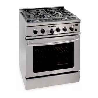
This manual contains information necessary for you to troubleshoot a DCS RGSC-305 self cleaning range. If the technical
data you are looking for is not contained in this publication please call our technical support department at 888-396-2665
between the hours of 6:00 a.m. to 4:30 p.m. pacific standard time, Monday thru Friday.
Anytime you need information, or parts you will need a complete model and serial number. The rating plate is located
behind the kickpanel, on the right side of the frame. DCS uses model numbers which describe the type of unit they
represent. "RGSC" designates range, gas, self-cleaning. The number 305 indicates a 30" five burner range.
We have included sections on cooking and installations. In some cases a service problem is directly related to an improper
installation or not following correct cooking practices. The information contained in these sections should help you in
determining the origin of the condition for which the customer is concerned.
WARNING
If the information in this manual is not followed exactly, a fire or explosion may result causing
property damage, personal injury or death.
WARNING
Do not store or use gasoline or other flammable vapors and liquids in the vicinity of this or any
other appliance.
FOR YOUR SAFETY
If you smell gas:
Do not try to light any appliance.
Do not touch any electrical switch; do not use any phone in your building.
Immediately call your gas supplier from a neighbor's phone. Follow the gas
supplier's instructions.
If you cannot reach your gas supplier, call the fire department.
Installation and service must be performed by a qualified installer, service agency or the gas
supplier.
PLEASE RETAIN THIS MANUAL FOR FUTURE REFERENCE.
www.dcsappliances.com
1
Advertisement
Table of Contents

Related Manuals for DCS RGSC-305


Summary of Contents for DCS RGSC-305
-
Page 1: Introduction
Anytime you need information, or parts you will need a complete model and serial number. The rating plate is located behind the kickpanel, on the right side of the frame. DCS uses model numbers which describe the type of unit they represent. -
Page 2: Table Of Contents
TABLE OF CONTENTS INTRODUCTION ......................................1 SAFETY PRACTICES AND PRECAUTIONS ..........................3-5 INSTALLATION ......................................6-11 Cabinet Preparation ..................................6-7 Electrical Connections..................................8 Gas Hook-up....................................9-10 Anti-Tip Device Installation................................10 Backguard Installation ..................................11 Flame Characteristics ..................................11 COOKTOP USE ......................................12-13 OVEN USE ........................................14-15 Convection Baking / Broiling.................................14 Set Oven For Baking ..................................15 Set Oven For Broiling.................................16-17 CARE AND MAINTENANCE ..................................18... -
Page 3: Safety Practices And Precautions
SAFETY PRACTICES & PRECAUTIONS When properly cared for, your new DCS Appliance has Children should not be left alone or unattended in an area where appliances are in use. They been designed to be a safe, reliable cooking appliance. should never be allowed to turn knobs, push When using this restaurant caliber appliance, use it with buttons, sit or stand on any part of an appliance. - Page 4 SAFETY PRACTICES & PRECAUTIONS cooking performance and can damage the finish Hold the handle of the pan to prevent of the oven or the cooktop parts. movement of the utensil when stirring or turning food. WARNING: GREASE IS FLAMMABLE. Let hot grease cool This appliance is for cooking.
- Page 5 SAFETY PRACTICES & PRECAUTIONS California Proposition 65 - Warning:The burning of gas cooking fuel generates some by-products which are known by the State of California to cause cancer or reproductive harm. California law requires businesses to warn customers of potential exposure to such substances. To minimize exposure to these substances, always operate this unit according to the instructions contained in this booklet and provide good...
-
Page 6: Installation
(see Fig. 2). When clearance to combustible Fig. 1 are required. The same clearances apply to island material is over 12", a DCS island trim may be used (see installations . Fig. 2). The range comes equipped with island trim 2) The range can be placed in various positions with standard. - Page 7 INSTALLATION min. 30" wide hood CAUTION: 36" min. to 12" min. to combustible combustible material , each side material , from cooking surface cooking surface electrical + gas supply 35-3/8" max. for level counter, 36-3/4" max. with range 7-1/2" leveling legs fully extended 18"...
-
Page 8: Electrical Connections
INSTALLATION ELECTRICAL / GAS CONNECTIONS POWER REQUIREMENTS 120VAC, 60 Hz., single phase. Receptacle Box 4 Amp. Max. Cover Plate (Use 15 Amp. Circuit) Always disconnect electric supply cord from the wall outlet or service disconnect before servicing this Three appliance. Observe all governing codes and ordinances Prong Plug when grounding, in the absence of which, observe... -
Page 9: Gas Hook-Up
INSTALLATION ELECTRICAL / GAS CONNECTIONS HOOKUP A manual valve is installed in an accessible location from the front for the purpose of shutting off the gas supply. The supply line must not protrude beyond the back of the unit. Make sure the gas supply is turned off before connecting the appliance. -
Page 10: Anti-Tip Device Installation
ANTI-TIP DEVICE INSTALLATION INSTRUCTIONS ANTI-TIP DEVICE INSTALLATION (2) Wood Screws into All ranges must have an anti-tip device correctly installed Back Wall (All as per these instructions. If you pull the range out from Installations) (2)Small Holes for the wall for any reason, make sure that the device is Wood Installations properly engaged when you push the range back against the wall. -
Page 11: Backguard Installation
BACKGUARD INSTALLATION BACKGUARD INSTALLATION The backguard is installed after the gas connection is Wall Mount Full made.The backguard must be installed when there is less Backguard than a 12" clearance between combustibles and the back (Model No. BGS-3030) of the range (above the cooking surface) (See Fig. 1, Wall Mount Low page 3). -
Page 12: Cooktop Use
COOKTOP USE BURNERS The professional gas range is equipped with burners typical of those used in restaurants. These burners are designed for maximum cleanability and controllability. The large cap spreads the simmer burner heat out to avoid too much heat being concentrated on the center of the pan.The simmer burner is always on when the burner Simmer is in use. -
Page 13: Cooktop Use
COOKTOP USE ELECTRONIC IGNITERS If a burner does not ignite, listen for the clicking sound. If the igniter is not clicking, TURN OFF THE BURNER. Check the circuit breaker for a blown fuse or a tripped circuit breaker. (Fig. 15) BURNER EFFICIENCY AND FLAME CHARACTERISTICS It is necessary to keep the burner ports and the igniters... -
Page 14: Oven Use
OVEN USE GENERAL Bake push the Convection Bake button (located on the control Panel) and turn the oven control knob to the Your large new oven can be used in four cooking modes; temperature desired. convection bake, regular bake, convection broil, or regular broil. -
Page 15: Set Oven For Baking
OVEN USE Converting Recipes to Convection Bake convection baking. Place the rack(s) in the desired position before turning the oven on. Store the unused Low sided baking utensils will give the best results as the racks out of the oven. hot air can reach all sides of the food easier. -
Page 16: Set Oven For Broiling
OVEN USE cook slightly faster than the food on the upper rack, USING CONVECTION BROIL AND BROIL particularly if you are using large baking utensils. If you To Set the Oven for Convection Broil and are using two racks simultaneously, be sure to stagger Broil the baking utensils so that one is not directly above the other and the heated air can circulate freely around each... - Page 17 OVEN USE browned on rack position 2 (see instructions below for Using a Meat Thermometer to Broil and Convection Broil more information). (The numbering of the rack positions is from the bottom to the top - #1 being the bottom To accurately determine the doneness of a thick steak or position) chop (1-1/2 inches thick or more), use a meat...
- Page 18 OVEN USE NOTES: To dehydrate food, follow suggestions in a recipe. High Altitude Baking To warm plates, check with the dishware Recipes and baking times vary if you are baking at a manufacturer for the temperature for the high altitude. For accurate information write to the recommended.
-
Page 19: Care And Maintenance
CARE AND MAINTENANCE BURNERS For proper lighting and performance keep the burners clean. It is necessary to clean the burners if they do not light even though the igniter clicks, if there has been a severe boil over, or when the flame does not burn blue. Be certain all burner knobs are in the off position before Brass Ring Locating Pin... -
Page 20: Baker Igniter
SEALED BURNER DISASSEMBLY TO REPLACE THE BURNER IGNITERS, FOLLOW THESE STEPS: A) Remove burner cap (#1). B) Remove main burner port ring (#2). C) Using a 11/16” socket remove the brass nut (#3), which secures the simmer ring (#4). D) Remove the simmer ring. E) Using a 13/16”... -
Page 21: Component Access
NOTE: Light pressure If this procedure does not correct the misalignment, may have to be DOOR HINGE ROLLER contact DCS Customer Care Center (See page 51). applied on the door to close the hinge latch- KICK PANEL REMOVAL 1. -
Page 22: Convection Fan
COMPONENT ACCESS 4. Remove four 7/16” bolts holding convection motor assembly (fig 29). Motor Fig. 25 5. Follow wire through oven wall to connection below. Remove wire nut (fig. 26 and 27). Fig. 29 5. Support motor assembly inside oven and remove wire nuts. -
Page 23: Regulator Manifold Assembly
COMPONENT ACCESS REGULATOR MANIFOLD ASSEMBLY 1. Pull oven away from wall, making sure gas and electri- cal supply is turned off at the valve, and gas line is dis- connected. 2. Loosen and remove 15/16” brass flare nut from aluminum gas feed line at bottom, center of unit (fig. -
Page 24: Broiler Assembly/Igniter Removal
COMPONENT ACCESS BROILER ASSEMBLY/IGNITER REMOVAL WARNING: Disconnect circuit breaker and turn off the main gas valve prior to performing the following procedure... 1. Remove the three (3) phillips screws securing the wire cover panel located in the top of the oven door opening (fig. - Page 25 COMPONENT ACCESS 6. Remove inner panel phillips screw (1) located on the 9. Remove the 5/16” hex head screw (1) located on the left, front, side panel (fig. 42). right side panel of the opening (fig. 45). Fig. 42 Fig. 45 7.
- Page 26 COMPONENT ACCESS 13. Remove the two phillips screws (2) securing the 16. Remove the two (2) 5/16 “ hex head screws securing center bracket to the panel. Remove the bracket by the igniter assembly (fig. 51). lifting up and out. Remove the two (2) phillips screws located on the left and right side of the panel.
-
Page 27: Control Panel Removal
COMPONENT ACCESS WARNING: 6. Remove selector switch mounting screws (fig. 61). For safety reasons, it is essential that 7. Remove selector switch and bracket. these insulating materials 8. Remove wires. Note wire location on switch. reinstalled after servicing the unit in exactly the same locations from which they were removed. -
Page 28: Top Assembly
COMPONENT ACCESS TOP ASSEMBLY 1. Pull oven away from wall, making sure gas supply is turned off at the valve, and gas line and electrical are disconnected. 2. Remove the four (4) phillips head screws from island trim where it attaches to the back panel (fig.56). Fig. -
Page 29: Oven Thermostat
COMPONENT ACCESS 5. Remove wire guard and trim assembly from front of Mounting Screw unit. (fig’s 57 & 58). 6. Remove the four (4) phillips head screws from bull nose trim assembly, two on either side (fig. 59). 7. Pull thermo bulbs from oven cavity 8. -
Page 30: Lock Thermostat
COMPONENT ACCESS CLEAN THERMOSTAT 1. Disconnect power supply. 2. Remove the four (4) #15 torx head screws from control Capillary Assembly panel (fig. 54). 3. Remove selector switch mounting screws (fig. 61). 4. Remove clean thermostat mounting screw (fig.65). 5. Remove wires from clean thermostat. 6. -
Page 31: Troubleshooting
TROUBLESHOOTING CONDITION CHECK Bake igniter 3.0 amp to 3.3 amp draw ATC continuity No Bake Oven T-Stat contacts Main gas valve “OFF” Selector switch contacts 30 – 33: 40 – 43 Dual safety valve continuity Broil igniter 3.0 amp to 3.3 amp draw HTC continuity Oven T –Stat contacts No Broil Main gas valve “OFF”... - Page 32 CLEAN RELAY LOCKING COMPONENT CLOSED CONTACTS 1) “Latch close switch” C - NC 2) “Selector switch” 35 - 55 3) “K4 Relay” 8 - 2 4) “K3 Relay” coil energized 5) “K3 Relay” 4 – 7 6) Lock Motor energized...
-
Page 33: Clean Relay
CLEAN RELAY HEATING (LOCKED) COMPONENT CLOSED CONTACTS 1) “Latch close switch” C - NO 2) “Selector switch” 39 - 38 3) “Clean timer” 1 - 2 4) “K1 Relay” coil energized 4a) “Blower motor” energized ( K1 ) 4 - 7 4b) “Air switch”... - Page 34 CLEAN RELAY UNLOCKING COMPONENT CLOSED CONTACTS 1) “Selector switch”“Off” pos. 2) “Oven temperature less than 550°F 3) “Latch open switch” C – NC 4) “Selector switch” 36 - 56 5) “Lock T-Stat” C – NO 6) “K4 Relay”coil, energized 6a) “K4 Relay” 9 - 6 6b) “Latch motor”...
-
Page 35: Push Button Switch
PUSH BUTTON SWITCH CLEAN CONV. BROIL BROIL CONV. BAKE BAKE 31 32 33 34 35 36 37 39 41 42 LEGEND OPEN CLOSED 39 37 36 35 34 33 32 31 38 57 56 55 CLEAN CONV BROIL BROIL CONV BAKE BAKE... -
Page 36: Oven & Broiler Igniter
OVEN AND BROILER IGNITER Both the bake and broil burners use a hot surface ignition provide a minimum of 2.9 amps of current flow in the system. The safety valve operates by current, not voltage. series circuit. The igniter should provide a current flow of The igniter resistance decreases, allowing more current to between 3.2 and 3.7 amps. -
Page 37: Service Bulletin
SERVICE BULLETIN FOOT KIT REPAIR – K-14355 Parts Part Number Rubber feet (12) 14355 Syringe/adhesive (1) 25301 Drywall screw 6 x 2-1/4 (1) 15103 Take the cap off the syringe by unscrewing it. Remove the bumper cap. Note: the rubber foot may be broken or missing. Apply a small amount of the adhesive in the grate hole. -
Page 38: Parts List
RANGE BODY ASSEMBLY ITEM PART NO. DESCRIPTION ITEM PART NO. DESCRIPTION 91658 RACK, OVEN (3 PLCS) 91682 KICK PLATE, SILVER 91682-01-PA KICK PLATE, WHITE 14052 30” OVEN GASKET 91657-02 WLDMT RLR SUPT LH (2 PLCS) 91682-02-PA KICK PLATE, BLACK 91944 WIRE GUARD COVER 18052-2 LEVEL LEG (AFTER TEST) - Page 39 ITEM PART NO. DESCRIPTION 12261-01 SIDE GRATE (R/L) 16127 SWITCH, OVEN LIGHT 12262-01 CENTER GRATE 15073 LOGO, DCS 15002-41 SCREW, TORX (#15) (4 PLCS) 15001-19 SCREW (10 PLCS) 14051-01 BUTTON, BLACK (6 PLCS) 91228 CTR HANGER BURNER 16399 SWITCH, PUSH BUTTON...
- Page 40 SAFETY VALVE ASSEMBLY ITEM PART NO. DESCRIPTION ITEM PART NO. DESCRIPTION 91502 SUPPORT, GAS TRAIN 13053 VALVE, SAFETY 18018-1 NIPPLE 1/2 NPT 15021-04 18044 VALVE, SHUT OFF 16430 CORD, POWER 15001-19 SCREW (2 PLCS) 13003 REGULATOR 91501 BRKT, MOUNT (2 PLCS) 91964 BRACKET 15001-19...
- Page 41 INFRARED BROILER ASSEMBLY ITEM PART NUMBER DESCRIPTION ITEM PART NUMBER DESCRIPTION 91195-PC ACCESS PANEL 91242 IR BURNER ASSEMBLY 15001-14 SCREW 91708 SPACER, AIR BROILER 15001-09 SCREW 91728-01 INSULATION 15001-03 SCREW 91245 PLATE, FRONT INSULATION BOX 15001-03 SCREW 15001-03 SCREW 15001-03 SCREW 15001-03 SCREW...
- Page 42 SEALED BURNER ASSEMBLY ITEM PART NO. DESCRIPTION 12272 BURNER CAP 12274 RING C PORT 15219 VENTURI NUT 12270 RING C SIMMER 13378 VENTURI 12304 C BURNER BASE 91545-PC VULCANO 12224 IGNITER 12211 SPRING 12231 “E” RING...
- Page 43 COOLING COMPONENTS ASSEMBLY ITEM PART NO. DESCRIPTION ITEM PART NO. DESCRIPTION 91659 COOLING FAN ASSEMBLY 91728-02 INSULATION, REAR PANEL 91212 BLOWER MOTOR MOUNT 91707-01 SHIELD EXHAUST TOP (RIGHT) 15001-12 SCREW (2 PLCS) 91730-05 GASKET (2 PLCS) 91701 DEFLECTOR 91520-01 FLUE VENT R/H 15001-05 SCREW (2 PLCS) 91696...
- Page 44 CONVECTION ASSEMBLY ITEM PART NO. DESCRIPTION ITEM PART NO. DESCRIPTION 90276 MOTOR SUPPORT BRACKET 15001-32 SCREW (2 PLCS) 16327 CONVECTION FAN MOTOR 91214-PC BAFFLE, OVEN 16053 MOTOR COOLING BLADE 16130 CONVECTION BLADE 15029-02 CAGED NUT 15003-24 BOLT (4 PLCS) 90171 INNER WLDMT MOTOR CVR.
- Page 45 MANIFOLD/VALVES ASSEMBLY ITEM PART NO. DESCRIPTION ITEM PART NO. DESCRIPTION 91724 TUBE (GAS) 16415 SWITCH, IGNITER (5 PLCS) 18480 ELBOW 90º 1/2 NPT TO 5/8 TUBE 11252 3/16”TUBE ASSY SIMMER REAR 15021-08 NUT (2 PLCS) 18323 MANIFOLD 13390-06 GAS VALVE, NAT 12177 CLAMP, VALVE 13390-08...
- Page 46 GAS JET ASSEMBLIES ITEM PART NO. DESCRIPTION ITEM PART NO. DESCRIPTION 15219 NUT, VENTURI (5 PLCS) 11251 TUBE SIMMER (RIGHT FRONT) 18077-1 NUT, COMPRESSION (MAIN)(5) 11247 TUBE, MAIN (RIGHT FRONT) 18284 B-NUT 3/16” (SIMMER)(5 PLCS) 11248 TUBE, MAIN (RIGHT REAR) 11252 TUBE SIMMER (RIGHT REAR) 11252...
-
Page 47: Oven Burner Assembly
OVEN BURNER ASSEMBLY ITEM PART NO. DESCRIPTION ITEM PART NO. DESCRIPTION 15001-09 SCREW 91723 TUBE BAKE 91757 BRACKET, BURNER 15001-27 SCREW (4 PLCS) 91937 BURNER BOX 15071 NUT, STAMPED PAL NUT REPLACEMENT PART 91712 BRACKET 15001-09 SCREW 18052-2 ADJUSTABLE LEG 90 º... - Page 48 MOTORIZED LATCH ASSEMBLY ITEM PART NO. DESCRIPTION 16247 LATCH ASSEMBLY 15075-01 SPACER (2 PLCS)(.25 IN.) 15005-21 WASHER,MICA (2PLCS) 15001-09 SCREW, BLK (2 PLCS) 15001-14 SCREW (2 PLCS) 91195-PC ACCESS PANEL, PORC.
- Page 49 ELECTRICAL ASSEMBLY ITEM PART NO. DESCRIPTION ITEM PART NO. DESCRIPTION 11238 GRMTS, IGN, WIRE (5 PLCS) 16045-3 RELAY (2) 16046-02 PILOT LIGHT ASSY (5) 16045-2 RELAY 16009-1 BROIL IGNITER ASSY 15001-19 SCREW (2 PLCS) 91244 IGNITER BRACKET 16464 TRANFORMER 15001-03 SCREW (2 PLCS) 13043 HI TEMP CUT OUT...
- Page 50 LOWER ELECTRICAL ASSEMBLY ITEM PART NO. DESCRIPTION 15001-31 SCREW 16352 TERMINAL BLOCK 15001-31 SCREW (2 PLCS) 16044-2 CLEAN TIMER 16045-3 RELAY (2 PLCS) 16045-2 RELAY 91509 ELEC. COMPONENTS BRACKET 91509 (NEW) ELEC. COMPONENTS BRACKET 15001-19 SCREW (2PLCS) 15001-41 SCREW 16464 TRANSFORMER 91711 TRANSFORMER BRACKET...
- Page 51 DOOR ASSEMBLY ITEM PART NUMBER DESCRIPTION ITEM PART NUMBER DESCRIPTION 12167 SPACER (2 PLCS)(BRT CHROME) DOOR ASSEMBLIES: 12239 DOOR HANDLE 91687 • STAINLESS STEEL 96012 HANDLE STIFFENER (2 PLCS) 91687-01 • WHITE 15002-47 BOLT,1/4-28 UNF-2AX1.25GDS(4) 91687-02 • BLACK 91530 COVER GLASS TOP/BOTTOM 91532 SEAL DOOR UPPER 15001-14...
-
Page 52: Wiring Diagram / Schematic
WIRING DIAGRAM... - Page 53 WIRING SCHEMATIC...
-
Page 54: How To Obtain Service
SERVICE For warranty service, please contact your local service provider or DCS Customer Care Center at (888) 281-5698, Monday thru Friday, 6:00 am – 4:30 pm PST. Before you call, please have the following information ready: Model Number Serial Number... -
Page 55: Warranty
DCS to be defective. Replacement will be F.O.B. DCS, and DCS will not be liable for any transportation costs, labor costs, or export duties. This warranty shall not apply, nor can we assume responsibility for damage that might result from failure to follow manufactures instructions or local codes, where the appliance has been tampered with or altered in anyway or which, in our judgement, has been subjected to misuse, negligence, or accident. - Page 56 NOTES...
- Page 57 5800 Skylab Road, Huntington Beach, CA 92647 Tel: 714.372.7000 • Fax: 714.372.7001 Customer Service: (888) 281-5698 www.dcsappliances.com As product improvement is an ongoing process at DCS, we reserve the right to change specifications or design without notice. P/N 17559 Rev. A...
- Page 58 30” FIVE BURNER SELF CLEANING GAS RANGE Service Manual MODELS: RGSC-305SS RGSC-305BK RGSC-305WT...
Need help?
Do you have a question about the RGSC-305 and is the answer not in the manual?
Questions and answers