Table of Contents
Advertisement
Quick Links
Advertisement
Table of Contents

Related Manuals for Fujitsu PRIMERGY RX300 S6


Summary of Contents for Fujitsu PRIMERGY RX300 S6
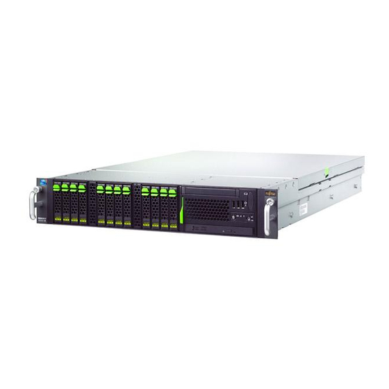
- Page 1 Options Guide - English PRIMERGY RX300 S6 Server Options Guide Edition July 2010...
-
Page 2: Copyright And Trademarks
All hardware and software names used are trademarks of their respective manufacturers. – The contents of this manual may be revised without prior notice. – Fujitsu assumes no liability for damages to third party copyrights or other rights arising from the use of any information in this manual. - Page 3 Before reading this manual For your safety This manual contains important information for safely and correctly using this product. Carefully read the manual before using this product. Pay particular attention to the accompanying manual "Safety notes and other important information" and ensure these safety notes are understood before using the product.
- Page 4 (hereafter, "high safety use"). Customers should not use this product for high safety use unless measures are in place for ensuring the level of safety demanded of such use. Please consult the sales staff of Fujitsu if intending to use this product for high safety use.
- Page 5 Only for the Japanese market: Although described in this manual, some sections do not apply to the Japanese market. These options and routines include: – Trusted Platform Module (TPM) Options Guide RX300 S6...
- Page 6 Options Guide 300 S6...
-
Page 7: Table Of Contents
Content Preface ......11 Concept and target groups ....12 Documentation overview . - Page 8 Contents Accessible drives and LSP/LSD ....55 Installing LSP or LSD ..... . 56 Installing an optical drive .
- Page 9 Contents Appendix ......123 11.1 Cable list ......123 11.2 Cabling plans .
- Page 10 Contents Options Guide 300 S6...
-
Page 11: Preface
The system was developed specifically for configurations with multiple servers (clusters), front-end solutions, e-commerce applications and ERP solutions. The PRIMERGY RX300 S6 is ideal for applications and operational areas that require maximum scalability, performance and availability in a space-saving rack cabinet. -
Page 12: Concept And Target Groups
The installation and removal of the hot-plug components is described in the Operating Manual supplied with the server. Documentation overview More information on your PRIMERGY RX300 S6 can be found in the following documents: – "Quick Start Hardware - PRIMERGY RX300 S6" leaflet "... - Page 13 Internet. The overview page showing the online documentation available on the Internet can be found using the URL (f o r EMEA market): http://manuals.ts.fujitsu.com. The PRIMERGY server documentation can be accessed using the Industry standard servers navigation option.
-
Page 14: Expansions And Conversions
Expansions and conversions Expansions and conversions Main memory The system board offers 18 slots for memory modules. 9 memory slots can be used in mono processor configurations. ECC with memory scrubbing and the Single Device Data Correction (SDDC) function is standard. There are three modes of operation for the main memory: –... - Page 15 (e.g. drive encryption using Windows Bitlocker Drive Encryption). The TPM is activated via the BIOS system (for more information, refer to the "D2619-N BIOS Setup Utility for PRIMERGY RX300 S6 and TX300 S6" manual). CAUTION! – When using the TPM, note the program descriptions provided by the third party manufacturers.
-
Page 16: Notational Conventions
Notational conventions – You must also create a backup of the TPM content. To do this, follow the third party manufacturer's instructions. Without this backup, if the TPM or the system board is faulty you will not be able to access your data. -
Page 17: Procedure
Ê Start the operating system and make the appropriate configuration if necessary (see the Operating Manual). For the l a test information on opti o nal products provided for the RX300 S6 see the configurator of this server: https://sp.ts.fujitsu.com/dmsp/docs/cnfgrx300s6.pdf Options Guide RX300 S6... - Page 18 Options Guide 300 S6...
-
Page 19: Safety Instructions
Safety instructions The following safety instructions are also provided in the manual "Safety notes and other important information". This device meets the relevant safety regulations for IT equipment. If you have any questions about whether you can install the server in the intended environment, please contact your sales outlet or our customer service team. - Page 20 Installation and operation CAUTION! This unit should not be operated in ambient temperatures above 35 °C. If the unit is integrated into an installation that draws power from an industrial power supply network with an IEC309 connector, the power supply's fuse protection must comply with the requirements for non- industrial power supply networks for type A connectors.
- Page 21 CAUTION! Ensure that the power sockets on the device and the properly grounded power outlets are freely accessible. The On/Off button or the main power switch (if present) does not isolate the device from the mains power supply. To disconnect it completely from the mains power supply, unplug all network power plugs from the properly grounded power outlets.
- Page 22 CAUTION! Proper operation of the system (in accordance with IEC 60950-1/2 resp. EN 60950-1/2) is only ensured if the casing is completely assembled and the rear covers for the installation slots have been fitted (electric shock, cooling, fire protection, interference suppression).
- Page 23 CAUTION! Install the screw removed during installation/detaching Internal Options in former device/position. To use a screw of the different kind causes a breakdown of equipment. The installation indicated on this note is sometimes changed to the kind of possible options without notice. Batteries CAUTION! Incorrect replacement of batteries may result in a risk of explosion.
- Page 24 Shocks and vibrations are also to be avoided. Do not insert any objects other than the specified CDs/DVDs/BDs. Do not pull on, press hard, or otherwise handle the CD/DVD/BD tray roughly. Do not disassemble the optical drive. Before use, clean the optical disk tray using a soft, dry cloth. As a precaution, remove disks from the optical drive when the drive is not to be used for a long time.
- Page 25 You can prevent damage from the optical drive and the CDs/DVDs/BDs, as well as premature wear of the disks, by observing the following suggestions: – Only insert disks in the drive when needed and remove them after use. – Store the disks in suitable sleeves. –...
- Page 26 The equipment and tools you use must be free of static charges. Only touch the components at the positions highlighted in green (touch points). Do not touch any exposed pins or conductors on a component. Use a grounding cable designed for this purpose to connect yourself to the system unit as you install components.
-
Page 27: Preparation
Preparation CAUTION! Before removing or attaching covers, turn off the server, all peripheral devices, and any other connected devices. Also unplug all power cords from the power outlet. Failure to do so can cause electric shock. Only for rack model: Use the anti-tilt plate to prevent the rack from tipping when installing the rack. -
Page 28: Removing The Server From The Rack
Removing the server from the rack Removing the server from the rack Ê Terminate all applications and shut down the server correctly. Ê If your operating system has not switched off the server, press the on/off button. Ê Pull all power connectors out of the power outlets. Figure 2: Knurled screws loosened and the server pulled out Ê... -
Page 29: Opening The Server
Opening the server Opening the server Figure 3: Removing the top cover Ê Press the two locks down. Ê Slide the cover back and take it off. Options Guide RX300 S6... -
Page 30: Removing The Air Duct
Removing the air duct Removing the air duct You only need to remo ve the air duct if you want to work in the area of the expansion cards, main memory or processors. Figure 4: Removing the air duct If you have installed an SAS/SATA RAID controller with a BBU: pay attention to the BBU cable when lifting off the air duct! If you want to remove the air duct from the server completely, first disconnect the BBU cable from the controller. -
Page 31: Removing The Fan Box
Removing the fan box Removing the fan box Figure 5: Removing the fan box Ê Push in the fan box locks on the right and left-hand side. Ê Pull the fan box straight up and out. Ê Place the fan box on the plate over the drives. Options Guide RX300 S6... -
Page 32: Removing The Power Supply Cage
Removing the power supply cage Removing the power supply cage Removing the power supply and dummy module Figure 6: Removing the power supply dummy module Ê Unlock the dummy module and pull it out. Figure 7: Removing the power supply module Options Guide 300 S6... - Page 33 Removing the power supply cage Ê Unlock the power supply module and pull it out. Figure 8: Removing the power supply cage Ê Remove the two screws (yellow circles) on the upper rear side. Ê Loosen the four captive screws (blue circles). Ê...
- Page 34 Removing the power supply cage Options Guide 300 S6...
-
Page 35: Main Memory
Main memory CAUTION! Before installing/removing memory to/from the server, turn off the server, all peripheral devices, and any other connected devices. Also unplug all power cords from the power outlet. Failure to do so can cause electric shock. A memory module consists of parts that are very vulnerable to damage by static electricity, and can easily be damaged by static electricity in the human body . -
Page 36: Population Rules
Population rules Population rules The system board supports up to 192 GB main memory. There are 18 slots available for the main memory. Each slot can be populated with 1 GB, 2 GB single or dual rank UDIMM or 1 GB, 2 GB, 4 GB, 8 GB, 16 GB single, dual or quad rank RDIMM memory modules (1 GB memory modules for the Japanese market only). - Page 37 Population rules There are three modes of operation for the main memory: – Independent Channel Mode (maximum memory configuration) The populated memory in the 6 channels (A-F) can be used in full (max. 192 GB). – Mirrored Channel Mode (maximum security) Only the populated memory in the 2 channels A and D can be used (max.
-
Page 38: Expanding The Main Memory
Expanding the main memory Expanding the main memory Ê Open the server as described in chapter "Preparation" on page Ê Remove the air duct over the main memory (see "Removing the air duct" on page 30). Figure 10: Removing a memory module Ê... - Page 39 Expanding the main memory Ê Insert the air duct back into the server (see section "Inserting the air duct" on page 118). Ê Return the housing cover to its position (see section "Closing the server" on page 119). Ê Close the server, connect it to the power outlet, and switch it on as described in the chapter "Completion"...
- Page 40 Expanding the main memory Options Guide 300 S6...
-
Page 41: Processors
Processors CAUTION! Before installing/removing processors to/from the server, turn off the server, all peripheral devices, and any other connected devices. Also unplug all power cords from the power outlet. Failure to do so can cause electric shock. Do not touch the circuitry on boards and soldered parts. Hold the metallic areas or the edge of the circuit boards. -
Page 42: Installing A Second Processor
Installing a second processor Installing a second processor The system board can be upgraded with a second processor. The upgrade kit consists of a processor and a heat sink. CAUTION! Only identic processors may be used on the system board. Both processors must have the same clock frequency and the same cache. - Page 43 Installing a second processor Figure 13: Opening the processor holder Ê Open the processor holder. Figure 14: Removing the socket cover Options Guide RX300 S6...
- Page 44 Installing a second processor Ê Take hold of the socket cover by the handles. Lift the socket cover straight up and off. CAUTION! If the socket cover is tilted when it is lifted off, the contact springs of the processor socket will be damaged. Figure 15: Slot for second CPU, socket coding and marking Figure 16: Inserting the processor Options Guide...
- Page 45 Installing a second processor Ê Position the new processor above the socket, and press it into the socket. CAUTION! The processor can only be installed in one particular direction. Note the marking on one of the corners. CAUTION! If the processor is tilted when it is inserted, the contact springs of the processor socket will be damaged.
- Page 46 Installing a second processor Figure 18: Engaging the socket release lever Ê Engage the socket release lever. Options Guide 300 S6...
- Page 47 Installing a second processor Installing the heat sink Figure 19: Installing the heat sink Ê Remove the protective cover on the underside of the heat sink. When doing so, do not touch the thermal paste on the underside of the heat sink. Ê...
- Page 48 Installing a second processor Figure 20: Closing the heat sink retention levers Ê Close the two heat sink retention levers at the same time. Ê Engage the two heat sink retention levers. CAUTION! Never install a processor without a heat sink. Doing so may cause the processor to overheat.
-
Page 49: Replacing The Processor
Replacing the processor Replacing the processor CAUTION! Only identic processors may be used on the system board. The second processor must have the same clock frequency and the same cache as the first processor. For dual operation, use a suitable multiprocessor operating system. - Page 50 Replacing the processor Figure 22: Disengaging the socket release lever Ê Open the socket release lever (1) and swing it up as far as possible. Ê Open the processor holder (2). Ê Carefully lift the installed processor, that remains in vertical position, up and out of the socket.
- Page 51 Replacing the processor Figure 23: Inserting the processor Ê Position the new processor over the socket and then carefully press it into the socket. CAUTION! The processor can only be installed in one particular direction. Pay attention to the marking on one of the corners and the socket coding. To avoid damaging the connections (pins) or the processor, do not force it into the socket.
-
Page 52: Replacing The Heat Sink
Replacing the heat sink Figure 24: Installing the heat sink Ê Close the two heat sink retention levers at the same time. Ê Replace the air duct over the main memory (see section "Inserting the air duct" on page 118). Ê... - Page 53 Replacing the heat sink When doing so, do not touch the thermal paste on the underside of the heat sink. Ê Place the heat sink on the processor socket (see section "Replacing the processor" on page 49). Ê Close the two heat sink retention levers at the same time. Ê...
- Page 54 Replacing the heat sink Options Guide 300 S6...
-
Page 55: Accessible Drives And Lsp/Lsd
Accessible drives and LSP/LSD CAUTION! Before installing/removing an accessible drive to/from the s erver, turn off the server, all peripheral devices, and any other connected devices. Also unplug all power cords from the power outlet. Failure to do so can cause electric shock. When installing an accessible drive, hold it by the side. -
Page 56: Installing Lsp Or Lsd
Installing LSP or LSD Installing LSP or LSD The ServerView Local Service Panel (LSP) and ServerView Local Service Display (LSD) are optional extra modules for PRIMERGY series servers. The display field allows you to read status reports directly on the server. These status reports provide you with information about the system and inform you of hardware errors (e.g. - Page 57 Installing LSP or LSD Removing the dummy module If you want to upgrade from the Local Service Panel to the Local Service Display, remove the Local Service Panel in the same way as the dummy module, and remove the cable when you have pulled the Local Service Panel right out.
- Page 58 Installing LSP or LSD Figure 27: Removing the dummy module Ê Pull out the dummy module frontward. Options Guide 300 S6...
- Page 59 Installing LSP or LSD Figure 28: Connecting the ServerView Local View Service Module Ê Thread the cable through the bay to the front. Ê Connect the cable to the ServerView Local Service Display. Options Guide RX300 S6...
- Page 60 Installing LSP or LSD Figure 29: Inserting the ServerView Local Service Module Carefully insert the ServerView Local Service Module horizontally to avoid damaging the EMC springs. Ê Push the ServerView Local Service Module right in. Further information on usage and display modes is provided in the documentation for the ServerView Local Service Panel or ServerView Local Service Display.
-
Page 61: Installing An Optical Drive
Installing an optical drive Installing an optical drive Ê Open the server as described in chapter "Preparation" on page Figure 30: Unlocking the dummy module Ê Unlock the dummy module. Ê Push the dummy module frontward. Carefully push the dummy module out horizontally to avoid damaging the EMC springs. - Page 62 Installing an optical drive Figure 31: Remove the dummy module Ê Remove the dummy module from the bay. CAUTION! Store the dummy module in a safe place. If you remove the accessible drive and do not replace it with a new one, the dummy module must be reinstalled to comply with EMC regulations and to satisfy cooling requirements and fire protection measures.
- Page 63 Installing an optical drive Figure 32: Installing an optical drive in the frame Ê Install the optical drive in the frame. Pay attention to the plastic pins that hol d the drive in the frame. Ê Thread the power cable and SATA cable through the bay. Figure 33: Connect the power and data cable.
- Page 64 Installing an optical drive Ê Connect the power cable to the optical drive (see the cabling plans in the chapter "Appendix" on page 123). Ê Connect the SATA cable to the drive (see the cabling plan in the chapter "Appendix" on page 123).
- Page 65 Installing an optical drive Figure 35: Connecting the SATA cable to the system board Ê Route the cable into the cable guide. Ê Connect the SATA cable to the connector SATA1 on the system board (see the cabling plans in the chapter "Appendix"...
-
Page 66: Usb Tape Drive/Usb Rdx Drive
USB tape drive/USB RDX drive USB tape drive/USB RDX drive A USB drive can only be installed in the 6x 3.5" and 8x 2.5" hard disk drive variant. Ê Open the server as described in section "Opening the server" on page Ê... - Page 67 USB tape drive/USB RDX drive Figure 37: USB tape drive Figure 38: USB RDX drive Options Guide RX300 S6...
- Page 68 USB tape drive/USB RDX drive Figure 39: Installing a USB tape drive in a drive cage Ê Insert the USB drive into the drive cage. Figure 40: Securing the USB tape drive with screws Ê Secure the USB tape drive with 2 screws (M3x4,5) on the left and right-hand side.
-
Page 69: Installing A Usb Drive
USB tape drive/USB RDX drive 7.3.1.2 Installing a USB drive Installing a USB tape drive Figure 41: Connecting the power supply adapter cable Ê Remove the power supply cable for the USB drive from the fan box holder. Ê Connect the adapter cable. Connecting the tape drive Figure 42: Pushing the power supply and USB cable frontward through the bay Ê... - Page 70 USB tape drive/USB RDX drive Figure 43: Connecting the cables to the USB tape drive Ê Connect the two cables to the USB tape drive. Figure 44: Pushing the USB tape drive into the server Ê Before pushing in the USB tape drive route the USB cable und the c onnector to the right side.
- Page 71 USB tape drive/USB RDX drive Figure 45: Installing a USB tape drive Ê Push the drive in. Make sure that the locking levers at both sides (see circles) are engaged. Press the locking levers outward. Ê When pushing in the drive, pull the cables back carefully to ensure that they do not become trapped.
- Page 72 USB tape drive/USB RDX drive Figure 47: Connecting the USB cable to the system board Ê Connect the USB cable to the system board in USB slot 1 (see cabling plan in the chapter "Appendix" on page 123). Options Guide 300 S6...
- Page 73 USB tape drive/USB RDX drive Figure 48: Routing cables in the fan box holder and air duct holder Ê Route the cables in the fan box holder and air duct holder as shown in the photograph. Ê Replace the fan box (see section "Installing a fan box"...
- Page 74 USB tape drive/USB RDX drive Installing a USB RDX drive Figure 49: Pushing the power supply and USB cable frontward through the bay Ê Push the power supply cable frontward through the bay. Ê Push the USB cable frontward through the bay. The black plug must be on the outside.
- Page 75 USB tape drive/USB RDX drive Ê When pushing in the drive, pull the cables back carefully to ensure that they do not become trapped. Figure 51: Installing a USB RDX drive Ê First route the cables to the right (see photograph) and then up, to ensure that the cables do not become trapped between the backplane and the USB drive module.
- Page 76 USB tape drive/USB RDX drive Figure 52: Connecting the USB cable to the system board Ê Connect the USB cable to the system board in USB slot 1 (see cabling plan in the chapter "Appendix" on page 123). Options Guide 300 S6...
- Page 77 USB tape drive/USB RDX drive Figure 53: Routing the USB cable and power supply cable through the fan box holder and air duct holder Ê Route the cables in the fan box holder and air duct holder as shown in the photograph.
-
Page 78: Installing A Usb Drive In The 8X 2.5" Variant
USB tape drive/USB RDX drive 7.3.2 Installing a USB drive in the 8x 2.5" variant In the 8x 2.5" variant, the DAT and RDX drive are installed using the same method, except for the cabling. 7.3.2.1 Installing a USB drive Figure 54: Removing a drive module Ê... - Page 79 USB tape drive/USB RDX drive Figure 55: Preparing the drive module Ê Remove the two screws on both sides. Ê Remove the cover. Figure 56: Inserting the USB drive into the drive module Options Guide RX300 S6...
- Page 80 USB tape drive/USB RDX drive Ê Insert the USB drive into the drive module. Ê Secure the drive with the 4 screws (M3x4). Figure 57: Inserting the drive module Ê Insert the drive module. CAUTION! When you push back the USB drive module, take care that the SAS backplane do not lay in front of the drive module.
-
Page 81: Connecting A Usb Drive
USB tape drive/USB RDX drive 7.3.2.2 Connecting a USB drive Connecting a USB tape drive Figure 58: Connecting the power supply cable Ê Connect the power supply cable to the USB drive. Options Guide RX300 S6... - Page 82 USB tape drive/USB RDX drive Figure 59: Connecting the USB cable Ê Connect the USB cable to the USB drive. Options Guide 300 S6...
- Page 83 USB tape drive/USB RDX drive Figure 60: Connecting the USB cable for the tape drive to the system board Ê Connect the USB cable to the system board in USB slot 1 (see cabling plan in the chapter "Appendix" on page 123).
- Page 84 USB tape drive/USB RDX drive Figure 61: Routing cables in the fan box holder and air duct holder Ê Route the cables in the fan box holder and air duct holder as shown in the photograph. Ê Replace the fan box (see section "Installing a fan box"...
- Page 85 USB tape drive/USB RDX drive Connecting a USB RDX drive Figure 62: Connecting the power supply cable Ê Connect the power supply cable to the USB drive. Figure 63: Connecting the USB cable Options Guide RX300 S6...
- Page 86 USB tape drive/USB RDX drive Ê Connect the USB cable to the USB drive. Figure 64: Connecting the USB cable for the tape drive to the system board Ê Connect the USB cable to the system board in USB slot 1 (see cabling plan in the chapter "Appendix"...
- Page 87 USB tape drive/USB RDX drive Figure 65: Routing cables in the fan box holder and air duct holder Ê Route the cables in the fan box holder and air duct holder as shown in the photograph. Ê Replace the fan box (see section "Installing a fan box"...
- Page 88 USB tape drive/USB RDX drive Options Guide 300 S6...
-
Page 89: Expansion Cards And Bbu
Expansion cards and BBU CAUTION! Before installing/removing expansion cards to/from the server, turn off the server, all peripheral devices, and any other connected devices. Also unplug all power cables from the power outlet. Failure to do so can cause electric shock. The circuit boards and soldered parts of internal options are exposed and can be damaged by static electricity. -
Page 90: Installing Expansion Cards
Installing expansion cards Installing expansion cards The system board offers seven low profile PCI slots: There are no hot-plug slots. In the standard setup, slot 1 is populated with a SAS/SATA RAID controller. You will find an overview of the slots in the technical manual for the system board D2619-N. -
Page 91: Upgrading A Sas/Sata Raid Controller
Upgrading a SAS/SATA RAID controller Figure 67: Installing a controller Ê Install the expansion card into the PCI slot and press it carefully into the associated plug-in location on the system board. Ê Secure the slot cover with the screw. Ê... - Page 92 Upgrading a SAS/SATA RAID controller Preparing a SAS RaidController for installation Figure 68: SAS RAID controller with a low profile slot cover Ê Secure the slot cover using the 2 screws in the square holes of the SAS/SATA RAID controller. Options Guide 300 S6...
- Page 93 Upgrading a SAS/SATA RAID controller Installing a SAS RAID controller Figure 69: Removing a controller Ê Remove the screw. Ê Loosen the two SAS cables. Ê Pull out the controller. Options Guide RX300 S6...
- Page 94 Upgrading a SAS/SATA RAID controller Figure 70: Installing a controller Ê Insert the SAS/SATA RAID controller into PCI slot 1 (1) and push it carefully to secure. Ê Secure the slot cover (2) with a screw. Ê Connect plug X1 to the upper slot and plug X2 to the lower slot of the controller (3).
-
Page 95: Installing A Bbu
Installing a BBU Installing a BBU CAUTION! Do not connect the cable using excessive force, the connector is weak. Follow the safety instructions in the chapter "Safety instructions" on page Ê Open the server as described in section "Opening the server" on page Ê... - Page 96 Installing a BBU Installing BBU 1 for SAS/SATA RAID controllers Figure 72: Connecting the BBU cable Ê Connect the BBU cable. Use the short cable for the controller in slot 1. The side of the plug with 2 pin rows must be facing upward. Figure 73: Screwing the BBU to the air duct Options Guide 300 S6...
- Page 97 Installing a BBU Ê Place the BBU on the air duct in such a way that the 3 holes are in line with the bolts on the BBU. Ê Secure the BBU to the air duct using the 3 screws. Figure 74: Inserting the air duct Ê...
- Page 98 Installing a BBU Figure 75: Connecting the BBU to a SAS/SATA RAID controller Ê Connect the connecting cable (BBU to controller) on the controller. The side of the plug with 2 pin rows must be facing upward. Options Guide 300 S6...
- Page 99 Installing a BBU Installing BBU2 for slot 7 Figure 76: Connecting the battery Ê Connect the BBU cable. Use the long cable for the controller in slot 7. The side of the plug with 2 pin rows must be facing upward. Ê...
- Page 100 Installing a BBU Figure 77: Securing BBU 2 to the holder for the 2 Ê Secure the BBU 2 to the holder for the 2 BBU using the 3 screws. Figure 78: Connecting BBU 2 to the controller Ê Insert the holder for the 2 BBU into the air duct.
- Page 101 Installing a BBU Figure 79: Connecting the cable to the controller Ê Connect the connecting cable (BBU to controller) on the controller. The side of the plug with 2 pin rows must be facing upward. Ê Push the cable behind the controller between the po wer supply cage and the controller.
- Page 102 Installing a BBU Options Guide 300 S6...
-
Page 103: Further Options
Further options CAUTION! Please note the safety instructions in chapter "Safety instructions" on page 19 T-handles Figure 80: Installing the T-handle Ê Remove the black pads (1) out of the square hole in the front cover. Ê Insert the handle from the front side (2). Ê... -
Page 104: Front Video Connector (Vga)
Front video connector (VGA) Front video connector (VGA) Ê Open the server as described in chapter "Preparation" on page Ê Remove the air duct as described in section "Removing the air duct" on page Figure 81: Removing a VGA cover Ê... - Page 105 Front video connector (VGA) Figure 82: Preparing the video connector Ê Remove both screws from the plug. Figure 83: Removing the fan box holder Ê Remove the cables from the fan box holder. Ê Loosen the screw and remove the fan box holder. Options Guide RX300 S6...
- Page 106 Front video connector (VGA) Figure 84: Removing the front panel frame Ê Push the locking lever up. Ê Pull the front panel frame inward and out. Options Guide 300 S6...
- Page 107 Front video connector (VGA) Figure 85: Installing the video connector in the front panel frame Ê Push the video connector through the front panel frame (1). Ê Tighten both screws (2). Options Guide RX300 S6...
- Page 108 Front video connector (VGA) Figure 86: Installing the front panel frame Ê Installing the front panel frame. Ê Push the front panel frame forward until it engages. Ê Replace the fan box holder, and secure with screws. Ê Route the cables in the fan box holder and air duct holder. Figure 87: Connecting the front VGA cable to the system board Options Guide 300 S6...
-
Page 109: Tpm
Ê Connect the front VGA cable to the system board. See cabling plan chapter "Appendix" on page 123. Ê Replace the fan box (see section "Installing a fan box" on page 115). Ê Close the server, connect it to the power outlet, and switch it on as described in the chapter "Completion"... - Page 110 Figure 89: Inserting the TPM spacer on the system board Ê Insert the TPM spacer into the hole on the system board. Figure 90: Installing the TPM Ê Insert the TPM on the system board. Options Guide 300 S6...
- Page 111 Figure 91: Securing a TPM Module Ê Fasten the TPM with the special screw for the TPM. Please use the TPM screwdriver insert bit to tighten the special screw. Do not fasten the screw too tightly (torque value of 0.6 Nm). Ê...
-
Page 112: Usb Flash Module (Ufm)
USB Flash Module (UFM) USB Flash Module (UFM) Figure 92: UFM installation kit USB Flash Module (UFM) UFM spacer UFM nylon screw Ê Open the server as described in section "Opening the server" on page Ê Remove the air duct as described in section "Removing the air duct"... - Page 113 USB Flash Module (UFM) Figure 93: Connecting the UFM to the system board Ê Connect the USB Flash Module to the system board. The spacer must click into the hole on the system board. Ê Insert the power supply cage as in section "Installing a power supply cage"...
- Page 114 USB Flash Module (UFM) Options Guide 300 S6...
-
Page 115: Completion
Installing a fan box Completion CAUTION! Please note the safety instructions in chapter "Safety instructions" on page 10.1 Installing a fan box Figure 94: Installing a fan box Ê Install the fan box perfectly straight. Ê Push fan box down until it engages. Make sure that all cables lie in fan box holder and air duct holder. -
Page 116: Installing A Power Supply Cage
Installing a power supply cage 10.2 Installing a power supply cage Figure 95: Installing a power supply cage Ê When installing the power supply cage, keep it perfectly straight and horizontal to avoid damaging the plugs on the system board, then push to secure. - Page 117 Installing a power supply cage Figure 96: Installing the power supply dummy module Ê Reinstall the dummy module and the po wer supply module(s), depending on the configuration. Options Guide RX300 S6...
-
Page 118: Inserting The Air Duct
Inserting the air duct 10.3 Inserting the air duct Figure 97: Inserting the air duct over the main memory and processors Ê Replace the air duct over the main memory and processors. Ê If a SAS/SATA RAID controller is installed and you loosened the BBU cable when removing the air duct, re-connect the BBU cable. -
Page 119: Closing The Server
Closing the server 10.4 Closing the server Figure 98: Closing the top cover Ê Replace the top cover. Ê Slide the cover forward. Ê Make sure that the locks engage. Options Guide RX300 S6... -
Page 120: Installing The Server In The Rack
Installing the server in the rack 10.5 Installing the server in the rack If you have not removed the server from the rack cabinet, please skip this section: Figure 99: Installing the server in the rack cabinet CAUTION! Ensure that the safety lock has been inserted before the server is inserted. - Page 121 Installing the server in the rack Ê Connect all power plugs to the power outlets. Ê Press the On/Off button to start up the server. Options Guide RX300 S6...
- Page 122 Installing the server in the rack Options Guide 300 S6...
-
Page 123: Appendix
Appendix 11.1 Cable list Cable # * Part number Code number Name T26139-Y3994-V1 A3C40097650 Front VGA T26139-Y3925-V303 A3C40097642 Front panel T26139-Y3928-V205 A3C40103930 SATA T26139-Y3807-V201 A3C40097864 Front USB cable T26139-Y3986-V301 A3C40097692 Optical / USB drive power supply for barebone model S26361-K1344-A100/A200 T26139-Y3986-V302 A3C40103416 Optical drive power supply for barebone model S26361-K1344-A300... - Page 124 Cable list Cable # * Part number Code number Name T26139-Y3963-V109 A3C40103414 SAS C2/X2 für 2.5"- backplane (barebone models S26361-K1344- A200 and S26361-K1344- A300) T26139-Y3973-V96 A3C40099017 Internal USB drives T26139-Y3987-V3 A3C40092034 BBU Slot 1 T26139-Y3987-V2 A3C40090454 BBU Slot 7 T26139-Y3969-V251 A3C40114137 SATA onboard (8 x2.5" only) The following table shows a cable overview: *Refers to the following cabling plans.
-
Page 125: Cabling Plans
System Board D2619-N H D D Inte rn only Inte rn USB1 only Inte rn USB2 only Fan backplane 6x3,5” 1 2 V/5 V backplane Figure 100: Cabling for PRIMERGY RX300 S6 with 3.5" hard disk drives Options Guide RX300 S6... - Page 126 Inte rn only Inte rn USB1 only only Inte rn USB2 only Fan backplane 6x3,5“ 1 2 V/5 V backplane Figure 101: Cabling for PRIMERGY RX300 S6 with 3.5" hard disk drives and 1 USB drive Options Guide 300 S6...
-
Page 127: Options Guide
Fan backplane 1 2 V/5 V 8x3 ,5 “ S A S b a ckp la n e Figure 102: Cabling for PRIMERGY RX300 S6 with 8x 2.5" hard disk drives and 1 USB drive Options Guide RX300 S6... - Page 128 Fan backplane 1 2 V/5 V 8x3 ,5 “ S A S b a ckp la n e Figure 103: Cabling for PRIMERGY RX300 S6 with 8x 2.5" hard disk drives and 1 USB drive Options Guide 300 S6...
- Page 129 Inte rn only Inte rn only USB1 Inte rn only USB2 Fan backplane 1 2 V/5 V S A S backplane 12x2,5 “ Figure 104: Cabling for PRIMERGY RX300 S6 with 12 x 2.5" hard disk drives Options Guide RX300 S6...
-
Page 130: Configuration Schema
11.3 Configuration schema Area for 9 slots for FAN1 PSU1 T4 (ambient memory PSU1 sensor, located at • Temp FAN2 PSU1 board) • FAN1 PSU2 2 • CPU 1 • PSU2 • Front VGA redundant FAN2 PSU2 Drive Area based on 3 different SAS - BP - 6 x 3,5”... -
Page 131: Index
Index accessible drives fan box fan box holder fan box lock Battery Backup Unit FD dummy module battery connecting cable 98, front panel frame unlocking installing front video connector (VGA) cable channel heat sink 47, cable list holder for the 2nd BBU cabling for RAID controllers connecting cable battery 98, connecting optical drive... - Page 132 Index low profile population rules main memory power supply cage power supply dummy module power supply module processor 14, processor coding processor cover processor marking processor socket cover rack RAID controller cabling RDX drive SAS cable SAS/SATA RAID controller security function ServerView Local Service Display 15, ServerView Local Service Panel 15,...