HP ProLiant DL580 G7 User Manual
Hide thumbs
Also See for ProLiant DL580 G7:
- Product end-of-life disassembly instructions (5 pages) ,
- User manual (131 pages) ,
- Quickspecs (52 pages)
Table of Contents
Advertisement
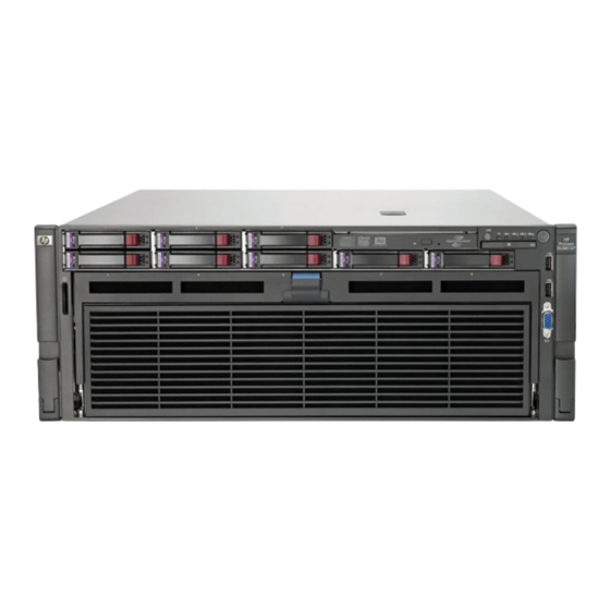
HP ProLiant DL580 G7 Server
User Guide
Abstract
This document is for the person who installs, administers, and troubleshoots servers and storage systems. HP assumes you are qualified in the
servicing of computer equipment and trained in recognizing hazards in products with hazardous energy levels.
Part Number: 595656-004
April 2011
Edition: 4
Advertisement
Table of Contents
Troubleshooting

Related Manuals for HP ProLiant DL580 G7


Summary of Contents for HP ProLiant DL580 G7
-
Page 1: User Guide
User Guide Abstract This document is for the person who installs, administers, and troubleshoots servers and storage systems. HP assumes you are qualified in the servicing of computer equipment and trained in recognizing hazards in products with hazardous energy levels. - Page 2 © Copyright 2010, 2011 Hewlett-Packard Development Company, L.P. The information contained herein is subject to change without notice. The only warranties for HP products and services are set forth in the express warranty statements accompanying such products and services. Nothing herein should be construed as constituting an additional warranty. HP shall not be liable for technical or editorial errors or omissions contained herein.
-
Page 3: Table Of Contents
Contents Component identification ....................... 7 Front panel components ..........................7 Front panel LEDs and buttons ........................8 Systems Insight Display ..........................9 Rear panel components ..........................10 Rear panel LEDs and buttons ........................11 Power supply LED ............................ 12 System board components ........................13 System maintenance switch ...................... - Page 4 Installing the PCI Express I/O expansion board ................. 60 Installing the PCI-X/PCI Express I/O expansion board ................ 62 HP NC524SFP Dual Port 10GbE Module option ..................64 Battery-backed write cache module ......................66 FBWC module and capacitor pack option ....................68 HP Trusted Platform Module option ......................
- Page 5 HP Insight Diagnostics survey functionality ..................82 Integrated Management Log ......................82 Remote support and analysis tools ......................83 HP Insight Remote Support software ....................83 Keeping the system current ........................83 Drivers ............................83 Version control ..........................84 ProLiant Support Packs ........................84 Operating System Version Support ....................
- Page 6 Grounding methods to prevent electrostatic discharge ................113 Specifications ........................... 114 Environmental specifications ........................114 Server specifications ..........................114 HP ProLiant 1200 W power supply specifications ..................115 Technical support ........................116 Before you contact HP ..........................116 HP contact information ........................... 116 Customer Self Repair ..........................
-
Page 7: Component Identification
Component identification Front panel components Item Description Serial and PID tag Optical drive Systems Insight Display USB connectors (2) Video connector Processor memory drawer Component identification 7... -
Page 8: Front Panel Leds And Buttons
Front panel LEDs and buttons Item Description Status UID button and LED Blue—Activated Blue (flashing)—Server being managed remotely Off—Deactivated Health LED Green—Normal (system on) Amber (flashing)—Internal system health degraded Red (flashing)—Internal system health critical Off—Normal (system off) NIC 1 LED Green—Linked to network Green (flashing)—Linked with activity on the network Off—No network connection... -
Page 9: Systems Insight Display
Systems Insight Display The Systems Insight Display LEDs represent the server and component layout. Description Off—No protection AMP status Green—Protection enabled Amber—Memory failure occurred Amber (flashing)—Memory configuration error Green—Normal (system on) Health Amber (flashing)—Internal system health degraded Red (flashing)—Internal system health critical Off—Normal (system off) Green—System on or requesting power on Power cap... -
Page 10: Rear Panel Components
Rear panel components Item Description Item Description Power supply bay 4 (optional) Expansion slot 2 (optional) Power supply bay 3 (optional) Expansion slot 3 (optional) Power supply bay 2 Expansion slot 4 (optional) Power supply bay 1 Expansion slot 5 (optional) Mouse connector Expansion slot 6 (optional) Serial connector... -
Page 11: Rear Panel Leds And Buttons
Rear panel LEDs and buttons Item Description LED color Status iLO 3 NIC Activity LED Green On or flashing—Network activity Off—No network activity iLO 3 NIC Link LED Green On—Linked to network Off—Not linked to network NIC 2 Activity LED Green On or flashing—Network activity Off—No network activity... -
Page 12: Power Supply Led
Power supply LED Power LED Status No AC power to power supply units. Check the AC power cord. AC is present. Standby output is on, output is disabled. Further indicated by the front panel LED. Power supply failure (includes overvoltage and overtemperature) further indicated by the Systems Insight Display LEDs. -
Page 13: System Board Components
System board components Item Description Optional I/O expansion board connectors: • PCI-X/PCI Express I/O expansion board • PCI Express I/O expansion board Slot 7 PCIe2 x8 (4, 2, 1) Slot 8 PCIe2 x8 (4, 2, 1) Slot 9 PCIe2 x16 (8, 4, 2, 1) Slot 10 PCIe2 x8 (4, 2, 1) Slot 11 PCIe2 x8 (8, 4, 2, 1) SPI board connector... -
Page 14: System Maintenance Switch
System maintenance switch The system maintenance switch (SW1) is an eight-position switch that is used for system configuration. The default position for all eight positions is Off. Position Description Function iLO 3 security Off = iLO 3 security is enabled. On = iLO 3 security is disabled. -
Page 15: Spi Board Components
SPI board components Item Description Mini SAS connectors (2) SAS cache connector TPM connector Fan data connector RMII connector SD card slot Battery 10Gb NIC connector NIC cache connector NIC 3 connector NIC 1 connector Video connector Keyboard connector USB connectors (2) iLO 3 connector Mouse connector Serial connector... -
Page 16: I/O Expansion Board Components
I/O expansion board components • PCI-X/PCI Express I/O expansion board Item Description Slot 6 PCIe2 x16 (16, 8, 4, 2, 1) Slot 4 PCIe2 x8 (4, 2, 1)* Slot 3 PCIe2 x16 (16, 8, 4, 2, 1) Slot 2 PCI-X Slot 1 PCI-X *Slot 4 is physically a x8 slot but operates electrically as a x4 slot. -
Page 17: Processors And Memory Cartridges
**Slots 2, 3, 5 and 6 are physically x16 slots but operate electrically as x8 slots. Processors and memory cartridges The processor memory drawer contains 4 processor sockets and 8 memory cartridges. For DIMM numbering, see "DIMM slot locations (on page 18)." For installation guidelines, see "Memory options (on page 43)."... -
Page 18: Dimm Slot Locations
DIMM slot locations Each memory cartridge contains 8 DIMM slots. The lockstep banks are identified by the letters A through D. For installation guidelines, see "Memory options (on page 43)." Device numbers Component identification 18... -
Page 19: Hard Drive Leds
Hard drive LEDs Item Description Fault/UID LED (amber/blue) Online LED (green) Hard drive LED combinations Online/activity Fault/UID LED Interpretation LED (green) (amber/blue) Alternating amber and The drive has failed, or a predictive failure alert has been On, off, or blue received for this drive;... -
Page 20: Battery Pack Leds
Online/activity Fault/UID LED Interpretation LED (green) (amber/blue) Steadily amber A critical fault condition has been identified for this drive, and the controller has placed it offline. Replace the drive as soon as possible. Amber, flashing A predictive failure alert has been received for this drive. Replace regularly (1 Hz) the drive as soon as possible. - Page 21 A fully-charged battery can normally preserve data for at least two days. The battery lifetime also depends on the cache module size. For further information, refer to the controller QuickSpecs on the HP website (http://www.hp.com). Double blink, then The cache microcontroller is waiting for the host controller to —...
-
Page 22: Fbwc Module Leds
FBWC module LEDs The FBWC module has two single-color LEDs (green and amber). The LEDs are duplicated on the reverse side of the cache module to facilitate status viewing. Green LED Amber LED Interpretation A backup is in progress. A restore is in progress. Flashing (1 Hz) The capacitor pack is charging. -
Page 23: Fan Locations
Fan locations Power supply backplane components Component identification 23... - Page 24 Item Description Graphics card power connector Graphics card power connector Graphics card power connector SAS backplane power connector Fan power connector Component identification 24...
-
Page 25: Operations
Operations Power up the server To power up the server, press the Power On/Standby button. Power down the server WARNING: To reduce the risk of personal injury, electric shock, or damage to the equipment, remove the power cord to remove power from the server. The front panel Power On/Standby button does not completely shut off system power. -
Page 26: Remove The Access Panel
Extend the server on the rack rails until the server rail-release latches engage. After performing the installation or maintenance procedure, slide the server into the rack by pressing the server rail-release latches. Remove the access panel WARNING: To reduce the risk of personal injury from hot surfaces, allow the drives and the internal system components to cool before touching them. -
Page 27: Processor Memory Drawer Shipping Screw Locations
Extend the server from the rack (on page 25). Open the locking latch, slide the access panel to the rear of the chassis, and remove the access panel. If the locking latch is locked, use a T-15 Torx screwdriver to unlock the latch. Processor memory drawer shipping screw locations Two orange shipping screws secure the processor memory drawer in place during shipping. -
Page 28: Access The Systems Insight Display
Release the latches on the release lever. Lower the handle, and then extend the processor memory drawer from the server until the release latches catch. WARNING: The processor memory drawer weighs more than 11.3 kg (25.0 lb). Use extra caution when removing and replacing the processor memory drawer. Firmly holding the processor memory drawer, press the release buttons and then remove the drawer from the server. -
Page 29: Remove The Spi Board
After the display fully ejects, rotate the display downward to view the LEDs. Remove the SPI board To remove the component: Power down the server (on page 25). Extend the server from the rack (on page 25). Remove the access panel (on page 26). Disconnect all cables from the SPI board. - Page 30 Raise the levers, and lift the SPI board from the server. Remove all components from the failed SPI board. To replace the component, reverse the removal procedure. Operations 30...
-
Page 31: Setup
(http://www.hp.com/services/carepack). Rack planning resources The rack resource kit ships with all HP branded or Compaq branded 9000, 10000, and H9 series racks. For more information on the content of each resource, refer to the rack resource kit documentation. If you intend to deploy and configure multiple servers in a single rack, refer to the white paper on high-density deployment at the HP website (http://www.hp.com/products/servers/platforms). -
Page 32: Optimum Environment
HP servers draw in cool air through the front door and expel warm air through the rear door. Therefore, the front and rear rack doors must be adequately ventilated to allow ambient room air to enter the cabinet, and the rear door must be adequately ventilated to allow the warm air to escape from the cabinet. -
Page 33: Power Requirements
Because of the high ground-leakage currents associated with multiple servers connected to the same power source, HP recommends the use of a PDU that is either permanently wired to the building’s branch circuit or includes a nondetachable cord that is wired to an industrial-style plug. NEMA locking-style plugs or those complying with IEC 60309 are considered suitable for this purpose. -
Page 34: Rack Warnings
Rack warnings WARNING: To reduce the risk of personal injury or damage to the equipment, be sure that: The leveling jacks are extended to the floor. • • The full weight of the rack rests on the leveling jacks. The stabilizing feet are attached to the rack if it is a single-rack installation. •... -
Page 35: Installing The Operating System
HP website (http://www.hp.com/support). Follow the on-screen instructions to begin the installation process. For information on using these installation paths, refer to the SmartStart installation poster in the HP ProLiant Essentials Foundation Pack, included with the server. Registering the server To register the server, refer to the HP Registration website (http://register.hp.com). -
Page 36: Hardware Options Installation
Hardware options installation Introduction If more than one option is being installed, read the installation instructions for all the hardware options and identify similar steps to streamline the installation process. WARNING: To reduce the risk of personal injury from hot surfaces, allow the drives and the internal system components to cool before touching them. - Page 37 3. To install the component: Update the system ROM. Locate and download the latest ROM version from the HP website (http://www.hp.com/support). Follow the instructions on the website to update the system ROM. Power down the server (on page 25).
- Page 38 Open the heatsink retaining bracket. CAUTION: Failure to completely open the processor locking lever prevents the processor from seating during installation, leading to hardware damage. Open the processor locking lever and the processor socket retaining bracket. Do not remove the processor socket cover.
- Page 39 If the processor has separated from the installation tool, carefully re-insert the processor in the tool. Handle the processor by the edges only, and do not touch the bottom of the processor, especially the contact area. Hardware options installation 39...
- Page 40 Align the processor installation tool with the socket, and then install the processor. THE PINS ON THE SYSTEM BOARD ARE VERY FRAGILE AND EASILY DAMAGED. CAUTION: THE PINS ON THE SYSTEM BOARD ARE VERY FRAGILE AND EASILY DAMAGED. To avoid damage to the system board: •...
- Page 41 Press the tabs on the processor installation tool to separate it from the processor, and then remove the tool. Close the processor socket retaining bracket and the processor locking lever. The processor socket cover is automatically ejected. Remove the cover. CAUTION: Be sure to close the processor socket retaining bracket before closing the processor locking lever.
- Page 42 Remove the heatsink protective cover. Install the heatsink. Close and lock the heatsink retaining bracket. Install the processor memory drawer cover. Install the processor memory drawer. Power up the server (on page 25). Hardware options installation 42...
-
Page 43: Memory Options
Depending on the processor model, the memory clock speed may be reduced to 1066 or 800 MHz. Memory overview The HP ProLiant DL580 G7 Server uses the next generation Intel® Xeon® Processor E7-series and 7500-series processor. This processor architecture departs radically from previous Intel Xeon front-side-bus-based architectures. -
Page 44: Dimm Identification
8500 = 1066-MHz DIMM type R = RDIMM (registered) For the latest supported memory information, see the QuickSpecs on the HP website (http://www.hp.com). DIMM installation guidelines This server supports two memory cartridges per processor. Each memory cartridge can support up to eight DIMMs. - Page 45 • DIMMs must be installed in pairs with identical characteristics. When possible, for configuration simplicity, HP recommends using DIMMs with identical part numbers throughout the system. • DIMM pairs must be populated in sequence by letter designation. Install DIMM pair (1A, 8A) first, followed by DIMM pair (3B, 6B), DIMM pair (2C, 7C) and DIMM pair (4D, 5D).
-
Page 46: Memory Cartridge Population Guidelines
The minimum memory cartridge population is one per processor. For best performance, two memory cartridges per processor are recommended. • Due to higher memory access latencies, HP does not recommend installing a processor without its corresponding memory cartridges. • To maximize performance in multi-processor configurations, distribute the total memory capacity evenly across all processors. -
Page 47: Memory Subsystem Architecture
Memory subsystem architecture The Intel® Xeon® Processor E7 and 7500 processor memory architecture is designed to take advantage of multiple stages of memory interleaving to reduce latency and increase bandwidth. Each Intel Xeon Processor E7 and 7500 processor contains two memory controllers as shown in the illustration below. -
Page 48: Memory Performance Optimization
1 and 2 are not identical to cartridges 3 and 4. Memory performance optimization The HP ProLiant DL580 G7 Server supports 64 DIMMs across four multi-core processors. While there are many DIMM population configurations that can support any total memory size, optimal performance is achieved when populated DIMMs can take advantage of the Intel®... -
Page 49: Memory Ras
• The largest contributor to maximum memory bandwidth performance is to use both memory controllers inside the processor. To achieve maximum memory bandwidth performance, populate both memory cartridges for each installed processor. • The second largest contributor to performance is to populate each DDR3 channel in each memory cartridge. -
Page 50: Advanced Ecc Memory Population Guidelines
AMP modes are configured in RBSU. If the requested AMP mode is not supported by the installed DIMM configuration, the server boots in Advanced ECC mode. For more information, see "HP ROM-Based Setup Utility (on page 75)." For the latest memory configuration information, see the QuickSpecs on the HP website (http://www.hp.com/go/ProLiant). -
Page 51: Mirrored Memory Population Guidelines
However, the server cannot support DIMM sparing in this example if the 2-GB DIMMs are populated in the 1A/8A pair locations and the 4-GB DIMMs are populated in any of the remaining DIMM pair locations. This is because it violates the rule requiring that the spare rank size of DIMM pair 1A/8A (1 GB) be equal to or larger than the single rank size of the other DIMM pair locations, since the rank size of a 4-GB DIMM in pairs B, C, or D would be larger (2 GB) than the spare rank size of the 2-GB DIMM pair in 1A/8A (1 GB). - Page 52 Remove the processor memory drawer cover. Remove the memory cartridge. Open the memory cartridge cover. Open the DIMM slot latches. Hardware options installation 52...
-
Page 53: Hot-Plug Hard Drive Option
Install the DIMM. See "Memory options (on page 43)." Close the memory cartridge cover. Install the memory cartridge. Install the processor memory drawer cover. Install the processor memory drawer. Power up the server (on page 25). Hot-plug hard drive option When adding hard drives to the server, observe the following general guidelines: •... - Page 54 Drives should be the same capacity to provide the greatest storage space efficiency when drives are grouped together into the same drive array. For hard drive numbers, see "Device numbers (on page 18)." To install the component: Remove the hard drive blank. Prepare the SAS hard drive.
-
Page 55: Redundant Hot-Plug Power Supply Option
The server supports up to four hot-plug power supplies. Install all power supplies to provide full redundancy. HP recommends installing redundant hot-plug power supplies in pairs. To confirm the redundancy of your configuration, see the HP power advisor at the HP website (http://www.hp.com/go/hppoweradvisor). -
Page 56: Internal Solid State Drive Expansion Bay Option
Connect the power cord to the power source. Be sure that the power supply LED is green ("Power supply LED" on page 12). Be sure that the front panel external health LED is green ("Front panel LEDs and buttons" on page 8). Internal solid state drive expansion bay option Power down the server (on page 25). -
Page 57: Expansion Board Options
The cable and the cable arrangement may appear differently from shown. Install the access panel. Slide the server back into the rack. Power up the server (on page 25). Expansion board options The server supports up to 11 expansion slots. The server ships with 5 PCI Express expansion slots. To support the optional expansion slots, install one of the following options into the server: •... -
Page 58: Securing An Expansion Board For Shipping
Open the expansion board retainer, and then remove the expansion slot cover. Install the expansion board. Install the shipping screw, if necessary. For more information, see "Securing an expansion board for shipping (on page 58)." Close the expansion slot retainer. Connect any required internal or external cables to the expansion board. - Page 59 CAUTION: To prevent improper cooling and thermal damage, do not operate the server unless all expansion slots have either an expansion slot cover or an expansion board installed. Power down the server (on page 25). Extend the server from the rack (on page 25). Remove the access panel (on page 26).
-
Page 60: Installing The Pci Express I/O Expansion Board
Install the shipping screw. Close the expansion slot retainer. Install the access panel. Slide the server back into the rack. Power up the server (on page 25). Resume normal server operations. Installing the PCI Express I/O expansion board CAUTION: To prevent improper cooling and thermal damage, do not operate the server unless all expansion slots have either an expansion slot cover or an expansion board installed. - Page 61 Release the latches on the release lever. Lower the handle, and then extend the processor memory drawer from the server until the release latches catch. Remove the access panel (on page 26). Hardware options installation 61...
-
Page 62: Installing The Pci-X/Pci Express I/O Expansion Board
Install the PCI Express I/O expansion board. Install any expansion boards ("Installing a non-hot-plug expansion board" on page 57). Install the access panel. Slide the processor memory drawer back into the server. Slide the server back into the rack. Power up the server (on page 25). Installing the PCI-X/PCI Express I/O expansion board CAUTION: To prevent improper cooling and thermal damage, do not operate the server unless... - Page 63 Release the latches on the release lever. Lower the handle, and then extend the processor memory drawer from the server until the release latches catch. Remove the access panel (on page 26). Hardware options installation 63...
-
Page 64: Hp Nc524Sfp Dual Port 10Gbe Module Option
When installed on the SPI board, the HP NC524SFP Dual Port 10GbE Module provides two 10G NIC connectors for server I/O. When the HP NC524SFP module is installed, 1G NIC connectors 1 and 2 on the rear panel are unavailable. - Page 65 Install the mini-DIMM on the SPI board. Install the SPI board. Using a T-15 Torx screwdriver, remove the 10G NIC adapter blank. Save the retaining screw. Install the HP NC524SFP module on the SPI board. Hardware options installation 65...
-
Page 66: Battery-Backed Write Cache Module
Connect the network cables. Power up the server (on page 25). Battery-backed write cache module The HP BBWC protects against hard boot, power, controller, and system board failures. The server supports the following battery-backed options: • 256-MB cache module (standard) •... - Page 67 The BBWC consists of two parts: a battery pack and a storage cache module. Along with the cache module, the battery pack provides transportable data protection, increases overall controller performance, and maintains any cached data for up to 72 hours after the server loses power. The NiMH batteries in the battery pack are continuously recharged through a trickle-charging process whenever the system power is on.
-
Page 68: Fbwc Module And Capacitor Pack Option
Attach the cable to the cache module. Install the battery. Connect the cable to the battery. The SPI board is not shown for clarity. Install the access panel. Slide the server back into the rack. Power up the server (on page 25). FBWC module and capacitor pack option CAUTION: Do not use this controller with cache modules designed for other controller models,... - Page 69 To install the component: Back up all data. Close all applications. Power down the server (on page 25). CAUTION: In systems that use external data storage, be sure that the server is the first unit to be powered down and the last to be powered back up. Taking this precaution ensures that the system does not erroneously mark the drives as failed when the server is powered up.
-
Page 70: Hp Trusted Platform Module Option
Do not remove an installed TPM. Once installed, the TPM becomes a permanent part of the system board. • When installing or replacing hardware, HP service providers cannot enable the TPM or the encryption technology. For security reasons, only the customer can enable these features. Hardware options installation 70... -
Page 71: Retaining The Recovery Key/Password
Recovery Mode after BitLocker™ detects a possible compromise of system integrity. • HP is not liable for blocked data access caused by improper TPM use. For operating instructions, see the encryption technology feature documentation provided by the operating system. -
Page 72: Enabling The Trusted Platform Module
Install the TPM board. Press down on the connector to seat the board ("System board components" on page 13). Install the TPM security rivet by pressing the rivet firmly into the system board. Install the SPI board. Install the access panel. Slide the server back into the rack. - Page 73 OS application TPM settings. For more information on firmware updates and hardware procedures, see the HP Trusted Platform Module Best Practices White Paper on the HP website (http://www.hp.com/support).
-
Page 74: Cabling
Cabling DVD-ROM drive cabling Cabling 74... -
Page 75: Server Software And Configuration Utilities
Enabling access to the Array Configuration Utility (on page 78) and Erase Utility (on page 81) SmartStart is included in the HP Insight Foundation suite for ProLiant. For more information about SmartStart software, see the HP Insight Foundation suite for ProLiant or the HP website (http://www.hp.com/go/foundation). -
Page 76: Auto-Configuration Process
Selecting the primary boot controller • Configuring memory options • Language selection For more information on RBSU, see the HP ROM-Based Setup Utility User Guide on the Documentation CD or the HP website (http://www.hp.com/support/smartstart/documentation). Using RBSU To use RBSU, use the following keys: •... -
Page 77: Boot Options
For more information on RBSU, see the HP ROM-Based Setup Utility User Guide on the Documentation CD or the HP website (http://www.hp.com/support/smartstart/documentation). Boot options Near the end of the boot process, the boot options screen is displayed. This screen is visible for several seconds before the system attempts to boot from a supported boot device. -
Page 78: Array Configuration Utility
Mozilla Firefox 2.0 or later For Linux servers, see the README.TXT file for additional browser and support information. For more information, see the Configuring Arrays on HP Smart Array Controllers Reference Guide on the Documentation CD or the HP website (http://www.hp.com). -
Page 79: Option Rom Configuration For Arrays
If you do not use the utility, ORCA will default to the standard configuration. For more information regarding array controller configuration, refer to the controller user guide. For more information regarding the default configurations that ORCA uses, refer to the HP ROM-Based Setup Utility User Guide on the Documentation CD. -
Page 80: Management Tools
ASR increases server availability by restarting the server within a specified time after a system hang or shutdown. At the same time, the HP SIM console notifies you by sending a message to a designated pager number that ASR has restarted the system. You can disable ASR from the HP SIM console or through RBSU. -
Page 81: Erase Utility
ROM. USB support HP provides both standard USB 2.0 support and legacy USB 2.0 support. Standard support is provided by the OS through the appropriate USB device drivers. Before the OS loads, HP provides support for USB devices through legacy USB support, which is enabled by default in the system ROM. -
Page 82: Diagnostic Tools
Diagnostic tools HP Insight Diagnostics HP Insight Diagnostics is a proactive server management tool, available in both offline and online versions, that provides diagnostics and troubleshooting capabilities to assist IT administrators who verify server installations, troubleshoot problems, and perform repair validation. -
Page 83: Remote Support And Analysis Tools
If you are installing drivers from the SmartStart CD, be sure that you are using the latest SmartStart version that your server supports. To verify that your server is using the latest supported version, see the HP website (http://www.hp.com/support). For more information, see the documentation provided with the SmartStart... -
Page 84: Version Control
For example: http://www.hp.com/support/dl360g6 (http://www.hp.com/support/dl360g6) Version control The VCRM and VCA are Web-enabled Insight Management Agents tools that HP SIM uses to facilitate and schedule software update tasks to the entire enterprise. • VCRM manages the repository for Windows and Linux PSPs as well as online firmware. Administrators can browse a graphical view of the PSPs or configure VCRM to automatically update the repository with Internet downloads of the latest software from HP. -
Page 85: Hp Smart Update Manager
Downloads the latest components from Web (except Linux RPMs) • Enables direct update of BMC firmware (iLO and LO100i) For more information about HP Smart Update Manager and to access the HP Smart Update Manager User Guide, see the HP website (http://www.hp.com/go/foundation). Change control and proactive notification HP offers Change Control and Proactive Notification to notify customers 30 to 60 days in advance of upcoming hardware and software changes on HP commercial products. -
Page 86: Troubleshooting
Troubleshooting Troubleshooting resources The HP ProLiant Servers Troubleshooting Guide provides procedures for resolving common problems and comprehensive courses of action for fault isolation and identification, error message interpretation, issue resolution, and software maintenance on ProLiant servers and server blades. This guide includes problem-specific flowcharts to help you navigate complex troubleshooting processes. -
Page 87: Symbols On Equipment
Warnings and cautions WARNING: Only authorized technicians trained by HP should attempt to repair this equipment. All troubleshooting and repair procedures are detailed to allow only subassembly/module-level repair. Because of the complexity of the individual boards and subassemblies, no one should attempt to make repairs at the component level or to make modifications to any printed wiring board. -
Page 88: Symptom Information
If the problem occurs randomly, what is the duration or frequency? To answer these questions, the following information may be useful: • Run HP Insight Diagnostics (on page 82) and use the survey page to view the current configuration or to compare it to previous configurations. •... -
Page 89: Performing Processor Procedures In The Troubleshooting Process
To verify the server configuration, connect to the System Management homepage and select Version Control Agent. The VCA gives you a list of names and versions of all installed HP drivers, Management Agents, and utilities, and whether they are up-to-date. -
Page 90: Loose Connections
When requested to break the server down to the minimum configuration, uninstall the following components, if installed: • All additional DIMMs Leave only the minimum required to boot the server—either one DIMM or a pair of DIMMs. For more information, see the memory guidelines in the server user guide. •... -
Page 91: Service Notifications
LEDs. Depending on the model, the internal health LED and external health LED may either appear solid or they may flash. Both conditions represent the same symptom. For the location of server LEDs and information on their statuses, see the server documentation on the HP website (http://www.hp.com/support). -
Page 92: General Diagnosis Flowchart
Item "Symptom information (on page 88)" "Loose connections (on page 90)" "Service notifications (on page 91)" The most recent version of a particular server or option firmware is available on the HP Support website (http://www.hp.com/support). Troubleshooting 92... - Page 93 CD or the HP website (http://www.hp.com/products/servers/platforms) "Breaking the server down to the minimum hardware configuration (on page 89)" or in the HP ProLiant Servers Troubleshooting Guide located on the Documentation CD or see "Troubleshooting resources (on page 86)" • "Server information you need" in the HP ProLiant Servers Troubleshooting Guide located on the Documentation CD or see "Troubleshooting resources (on page 86)"...
-
Page 94: Server Power-On Problems Flowchart
Server power-on problems flowchart Symptoms: • The server does not power on. • The system power LED is off or amber. Troubleshooting 94... - Page 95 Item "Server health LEDs (on page 91)" and "Component identification (on page 7)" "HP Insight Diagnostics (on page 82)" or in the HP ProLiant Servers Troubleshooting Guide located on the Documentation CD or see "Troubleshooting resources (on page 86)" "Loose connections (on page 90)"...
- Page 96 Troubleshooting 96...
-
Page 97: Post Problems Flowchart
Server maintenance and service guide, located on the Documentation CD or the HP website (http://www.hp.com/products/servers/platforms). "Breaking the server down to the minimum hardware configuration (on page 89)" or in the HP ProLiant Servers Troubleshooting Guide located on the Documentation CD or see "Troubleshooting resources (on page 86)" •... - Page 98 Troubleshooting Guide located on the Documentation CD or see "Troubleshooting resources (on page 86)" • "Operating system information you need" in the HP ProLiant Servers Troubleshooting Guide located on the Documentation CD or see "Troubleshooting resources (on page 86)" Troubleshooting 98...
-
Page 99: Os Boot Problems Flowchart
Guide located on the Documentation CD or see "Troubleshooting resources (on page 86)" • Controller documentation "HP Insight Diagnostics (on page 82)" or in the HP ProLiant Servers Troubleshooting Guide located on the Documentation CD or see "Troubleshooting resources (on page 86)" •... -
Page 100: Server Fault Indications Flowchart
Server fault indications flowchart Symptoms: • Server boots, but a fault event is reported by Insight Management Agents • Server boots, but the internal health LED, external health LED, or component health LED is red or amber NOTE: For the location of server LEDs and information on their statuses, refer to the server documentation. - Page 101 "Power-on problems flowchart ("Server power-on problems flowchart" on page 94)" "HP Insight Diagnostics (on page 82)" or in the HP ProLiant Servers Troubleshooting Guide located on the Documentation CD or see "Troubleshooting resources (on page 86)" • "Hardware problems" in the HP ProLiant Servers Troubleshooting Guide located on the Documentation CD or see "Troubleshooting...
-
Page 102: Post Error Messages And Beep Codes
POST error messages and beep codes For a complete listing of error messages, refer to the "POST error messages" in the HP ProLiant Servers Troubleshooting Guide located on the Documentation CD or on the HP website (http://www.hp.com/support). Troubleshooting 102... - Page 103 WARNING: To avoid potential problems, ALWAYS read the warnings and cautionary information in the server documentation before removing, replacing, reseating, or modifying system components. Troubleshooting 103...
-
Page 104: Battery Replacement
Battery replacement If the server no longer automatically displays the correct date and time, you may need to replace the battery that provides power to the real-time clock. WARNING: The computer contains an internal lithium manganese dioxide, a vanadium pentoxide, or an alkaline battery pack. A risk of fire and burns exists if the battery pack is not properly handled. -
Page 105: Regulatory Compliance Notices
Regulatory compliance notices Regulatory compliance identification numbers For the purpose of regulatory compliance certifications and identification, this product has been assigned a unique regulatory model number. The regulatory model number can be found on the product nameplate label, along with all required approval markings and information. When requesting compliance information for this product, always refer to this regulatory model number. -
Page 106: Declaration Of Conformity For Products Marked With The Fcc Logo, United States Only
Hewlett-Packard Company P. O. Box 692000, Mail Stop 530113 Houston, Texas 77269-2000 • 1-800-HP-INVENT (1-800-474-6836). (For continuous quality improvement, calls may be recorded or monitored.) For questions regarding this FCC declaration, contact us by mail or telephone: • Hewlett-Packard Company P. -
Page 107: European Union Regulatory Notice
Compliance with these directives implies conformity to applicable harmonized European standards (European Norms) that are listed in the EU Declaration of Conformity issued by HP for this product or product family and available (in English only) either within the product documentation or at the following HP website (http://www.hp.eu/certificates) (type the product number in the search field). -
Page 108: Japanese Notice
This symbol on the product or on its packaging indicates that this product must not be disposed of with your other household waste. Instead, it is your responsibility to dispose of your waste equipment by handing it over to a designated collection point for the recycling of waste electrical and electronic equipment. -
Page 109: Chinese Notice
Do not operate controls, make adjustments, or perform procedures to the laser device other than those specified herein. Allow only HP Authorized Service technicians to repair the unit. • The Center for Devices and Radiological Health (CDRH) of the U.S. Food and Drug Administration implemented regulations for laser products on August 2, 1976. -
Page 110: Taiwan Battery Recycling Notice
To forward them to recycling or proper disposal, use the public collection system or return them to HP, an authorized HP Partner, or their agents. For more information about battery replacement or proper disposal, contact an authorized reseller or an authorized service provider. -
Page 111: Brazilian Notices
WARNING: Exposure to Radio Frequency Radiation—The radiated output power of this device is below the FCC radio frequency exposure limits. Nevertheless, human contact during normal operation should be minimized. Brazilian notices Este equipamento opera em caráter secundário, isto é, não tem direito a proteção contra interferência prejudicial, mesmo de estações do mesmo tipo, e não pode causar interferência a sistemas operando em caráter primário. -
Page 112: Taiwan Notices
Taiwan notices Regulatory compliance notices 112... -
Page 113: Electrostatic Discharge
Electrostatic discharge Preventing electrostatic discharge To prevent damaging the system, be aware of the precautions you need to follow when setting up the system or handling parts. A discharge of static electricity from a finger or other conductor may damage system boards or other static-sensitive devices. -
Page 114: Specifications
Specifications Environmental specifications Specification Value Temperature range* 10°C to 35°C (50°F to 95°F) Operating -40°C to 70°C (-40°F to 158°F) Shipping 28°C (82.4°F) Maximum wet bulb temperature Relative humidity (noncondensing)** 10% to 90% Operating 5% to 95% Non-operating * All temperature ratings shown are for sea level. An altitude derating of 1°C per 300 m (1.8°F per 1,000 ft) to 3048 m (10,000 ft) is applicable. -
Page 115: Hp Proliant 1200 W Power Supply Specifications
HP ProLiant 1200 W power supply specifications Specification Value Input requirements 100 to 120 VAC, 200 to Rated input voltage 240 VAC 50 Hz to 60 Hz Rated input frequency 10 A at 100 VAC Rated input current 4.9 A at 200 VAC... -
Page 116: Technical Support
If during the diagnosis period HP (or HP service providers or service partners) identifies that the repair can be accomplished by the use of a CSR part, HP will ship that part directly to you for replacement. There are two categories of CSR parts: •... - Page 117 HP specifies in the materials shipped with a replacement CSR part whether a defective part must be returned to HP. In cases where it is required to return the defective part to HP, you must ship the defective part back to HP within a defined period of time, normally five (5) business days. The defective part must be returned with the associated documentation in the provided shipping material.
- Page 118 HP sono realizzati con numerosi componenti che possono essere riparati direttamente dal cliente (CSR, Customer Self Repair). Se in fase di diagnostica HP (o un centro di servizi o di assistenza HP) identifica il guasto come riparabile mediante un ricambio CSR, HP lo spedirà direttamente al cliente per la sostituzione.
- Page 119 HP podrá cobrarle por el de sustitución. En el caso de todas sustituciones que lleve a cabo el cliente, HP se hará cargo de todos los gastos de envío y devolución de componentes y escogerá la empresa de transporte que se utilice para dicho servicio.
- Page 120 HP. Informatie over Service Partners vindt u op de HP website (http://www.hp.com/go/selfrepair). Reparo feito pelo cliente Os produtos da HP são projetados com muitas peças para reparo feito pelo cliente (CSR) de modo a minimizar o tempo de reparo e permitir maior flexibilidade na substituição de peças com defeito. Se, durante o período de diagnóstico, a HP (ou fornecedores/parceiros de serviço da HP) concluir que o reparo...
- Page 121 Opcional – Peças cujo reparo feito pelo cliente é opcional. Essas peças também são projetadas para o reparo feito pelo cliente. No entanto, se desejar que a HP as substitua, pode haver ou não a cobrança de taxa adicional, dependendo do tipo de serviço de garantia destinado ao produto.
- Page 122 Technical support 122...
- Page 123 Technical support 123...
-
Page 124: Acronyms And Abbreviations
Acronyms and abbreviations ABEND abnormal end Array Configuration Utility Advanced Memory Protection Automatic Server Recovery BBWC battery-backed write cache Canadian Standards Association DDDC Double Device Data Correction electrostatic discharge FBWC flash-backed write cache International Electrotechnical Commission iLO 3 Integrated Lights-Out 3 Integrated Management Log Acronyms and abbreviations 124... - Page 125 keyboard, video, and mouse network interface controller NVRAM non-volatile memory ORCA Option ROM Configuration for Arrays PCIe peripheral component interconnect express PCI-X peripheral component interconnect extended power distribution unit port ID POST Power-On Self Test ProLiant Support Pack QuickPath Interconnect Reliability, Availability, Serviceability RBSU ROM-Based Setup Utility...
- Page 126 Secure Digital SDDC Single Device Data Correction small form-factor Systems Insight Manager Scalable memory interfaces system peripheral interface TMRA recommended ambient operating temperature trusted platform module unit identification uninterruptible power system universal serial bus Version Control Agent Acronyms and abbreviations 126...
-
Page 127: Index
76 connector, USB 7, 10, 15 Automatic Server Recovery (ASR) 80 connector, video 7, 10, 15 contacting HP 116 CSR (customer self repair) 116 customer self repair (CSR) 116 Basic Input/Output System (BIOS) 77, 80, 92 battery 15, 104... - Page 128 HP Insight Diagnostics 82 memory overview 43 HP Insight Remote Support software 83 memory performance optimization 48 HP NC524SFP Dual Port 10GbE Module 64 memory RAS 49 HP ProLiant Essentials Foundation Pack 35 memory subsystem architecture 47 HP Smart Update Manager overview 84, 85...
- Page 129 rack, extending server from 25 RBSU (ROM-Based Setup Utility) 75, 77 online spare memory 77 RBSU configuration 76 operating systems 35, 84 rear panel buttons 11 operations 25 rear panel components 10 optimum environment 32 rear panel LEDs 11 Option ROM Configuration for Arrays (ORCA) 79 recommended ambient operating temperature options installation 34, 36 (TMRA) 32...
- Page 130 7, 10, 15 start diagnosis flowchart 91 static electricity 113 status lights, battery pack 20 support 83, 116 website, HP 116 support packs 75 wireless devices 110, 111, 112 supported operating systems 84 switch, system maintenance 13 symbols on equipment 87...
Need help?
Do you have a question about the ProLiant DL580 G7 and is the answer not in the manual?
Questions and answers