Table of Contents
Advertisement
Table of Contents
PART I English Edition
PART I English Edition
PART I English Edition
PART I English Edition
Chapter 1 Introduction ..................... ..........................................................1
1-1
Product Specifications ........................................................... 1
1-2
Package Contents ................................................................. 3
1-3
Mainboard Layout .................................................................. 4
1-4
Jumper and Connector Reference Page Chart ...................... 4
Chapter 2 Hardware Setup......................................................... .............. .5
2-1
Introduction to Jumpers .......................................................... 5
2-2
Installing a PGA type CPU in a ZIF Socket ............................. 6
2-3
Setting Your CPU's Parameters( SeePU Technology) ............ 7
2-4
Connector and Jumper Settings ........................................... 10
2-5
Main Memory Configuration ................................................. 16
Chapter 3 Award BIOS Setup Program ............................................ 19
3-1
Standard CMOS Setup ........................................................ 20
3-2
BIOS Features Setup ........................................................... 23
3-3
SeePU & Chipset Setup ...................................................... 26
3-4
Power Management Setup .................................................. 29
3-5
PnP/PCI Configuration ......................................................... 34
3-6
Load Setup Defaults ............................................................ 36
3-7
Integrated Peripherals .......................................................... 37
3-8
Supervisor Password & User Password Setting .................. 38
3-9
IDE HDD Auto Detection ..................................................... 40
3-10 Save and Exit Setup ............................................................ 40
3-11 Exit Without Saving .............................................................. 40
Chapter 4 Brief Software Driver Guide ............................................. 41
95 Device Manager Menu
Feature Explanations
Feature Explanations
Feature Explanations
Feature Explanations
Feature Explanations
SeePU Technology .......................................................................... 7
Software Power-Off Control ...................................................... 10/32
Power-On By Modem .................................................................... 10
Poly-fuse Over Current Protection ................................................ 11
Over-ride Power Button Connector ............................................... 12
iii
Advertisement
Table of Contents

Related Manuals for CHAINTECH 5TDM2


Summary of Contents for CHAINTECH 5TDM2
-
Page 1: Table Of Contents
Table of Contents PART I English Edition PART I English Edition PART I English Edition PART I English Edition PART I English Edition Chapter 1 Introduction ................1 Product Specifications ............1 Package Contents ..............3 Mainboard Layout ..............4 Jumper and Connector Reference Page Chart ...... - Page 2 Blinking LED in Suspend .............. 12 APTC Technology ................. 14 Management Extension Hardware for SMART Technology ..14 Power Failure Recovery ..............15 Flash BIOS Protection ..............27 Hardware Reset Protect ..............28 Power On by Alarm ............... 32 PART II Deutsche Anleitung (German Edition) PART II Deutsche Anleitung (German Edition) PART II Deutsche Anleitung (German Edition) PART II Deutsche Anleitung (German Edition)
-
Page 3: Part I English Edition
Introduction PART I English Edition1 Chapter 1 Introduction 1-1 Product Specifications r r r r r CPU - Supports up to 200MHz Pentium ® processors and up to 233MHz Pentium ® processors with MMX technology - Supports Cyrix/IBM 6x86 (processor rev. 2.7 or later)/6x86L PR150 PR200 and 6x86MX... - Page 4 Chapter 1 r BIOS - Award System BIOS - 1Mb Flash ROM - Supports PnP, APM, DMI & multi-device (such as floppy, IDE/SCSI, CD-ROM, etc.) booting features - Built-in Trend ChipAway Virus for a 100% virus-free system boot-up r r r r r Chipset - Intel 82430TX two chip PCIset r r r r r On Board Ultra I/O Functions - ITE8679 I/O chip...
-
Page 5: Package Contents
Introduction 1-2 Package Contents This product comes with the following components: r One mainboard r One 40-pin IDE connector ribbon cable (Figure 1-1) r One 34-pin floppy disk drive ribbon cable (Figure 1-2a) or (Figure 1-2b) r One 9-pin serial port and 25-pin parallel port ribbon cable with bracket (Figure 1-3) r One 25-pin serial port ribbon cable with bracket (Figure 1-4a), or same combination with optional PS/2 mouse connector (Figure1-4b) -
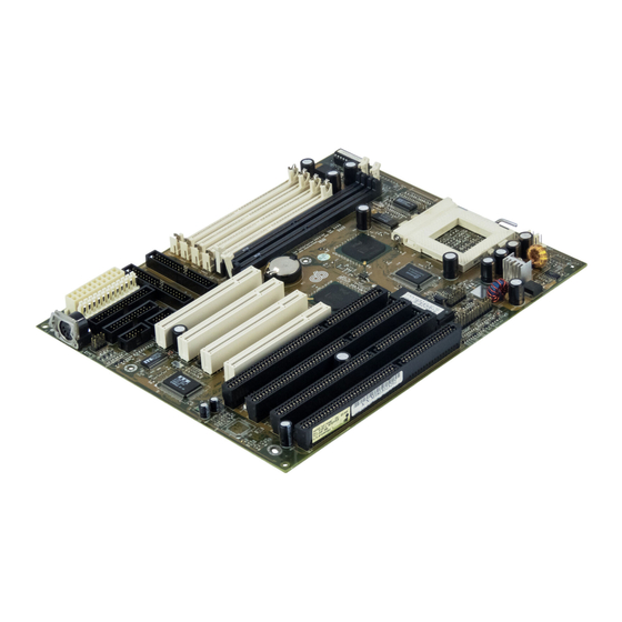
Page 6: Mainboard Layout
Chapter 1 1-3 Mainboard Layout 1-4 Jumper and Connector Reference Page Chart Jumper & Function Ref. page Connector No. ATX power supply connector AT power supply connector Infrared connector Dual channel USB connector Green switch connector Green LED connector System reset switch connector Turbo LED connector Keyboard lock &... -
Page 7: Chapter 2 Hardware Setup
Hardware Setup Chapter 2 Hardware Setup If your mainboard has already been installed in your computer you may still need to refer to this chapter if you plan to upgrade your system's hardware. Be sure to disconnect the power cable from the power source before performing any work on your mainboard, i. -
Page 8: Installing A Pga Type Cpu In A Zif Socket
Chapter 2 2-2 Installing a PGA type CPU in a ZIF Socket The Intel Socket 7, designed for the Pentium processor, has been incorporated as a standard mainboard specification and is compatible with AMD and Cyrix CPUs. To insert your CPU into Socket 7 please do the following: 1. -
Page 9: Setting Your Cpu's Parameters( Seepu Technology)
Hardware Setup 2-3 Setting Your CPU's Parameters( SeePU Technology) SeePU is a new user friendly technology that enables the user to setup a mainboard's CPU parameters through an easy to use BIOS setup procedure. It is no longer necessary to make many jumper settings as on conventional mainboards. 1. -
Page 10: Cpu Voltage
Chapter 2 ROM PCI / ISA BIOS (2A59IC3E) CPU & CHIPSET SETUP AWARD SOFTWARE, INC. AUTO Configuration : Enabled Spectrum Spread : Disabled DRAM Timing : 70ns Flash BIOS Protection : Disabled DRAM Leadoff Timing : 10/6/4 Hardware Reset Protect : Disabled DRAM Read Burst (EDO/FP) : x333/x444... -
Page 11: Hardware Setup
Hardware Setup The on board switching power module can automatically distinguish between these two types of processors. A protection circuit is employed such that if you enter a single voltage value for a dual voltage CPU (or vice versa), the incorrect voltage setting will not be made. -
Page 12: Connector And Jumper Settings
Chapter 2 2-4 Connector and Jumper Settings Connectors are used to link the system board with other parts of the system, including the power supply, the keyboard, and the various controllers on the front panel of the system case. The power supply connector is the last connection to be made while installing a mainboard. - Page 13 Hardware Setup AT Power Supply Connector (J6) Most power supplies have two sets of six-wire leads. Making sure the black wires of each lead are in the center, plug both leads into the AT power supply connector. The power supply requirement is as follows: AT Style Keyboard Connector (J2) Definition Keyboard Clock...
- Page 14 Chapter 2 Front Panel Connector Set (J15) A through G A. Over-ride Power Button Connector The power button on the ATX chassis can be used as a normal power switch as well as a button to activate Advanced Power Management Suspend mode. This mode is used for saving electricity when the computer is not in use for long periods of time.
- Page 15 Hardware Setup C. Green Switch/Green LED Connector Some ATX cases provide a Green switch which is used to put the system in Suspend mode. In suspend mode, the power supply to the system is reduced to a trickle, the CPU clock is stopped, and the CPU core is in it's minimum power state.
- Page 16 Chapter 2 System/CPU Cooling Fan Connector (J16/J17) These added connectors allow the fans to draw their power from the mainboard instead of the disk drive connector. some systems have all the disk drive power connectors in use. APTC Technology APTC (Active Processor Temperature Control) Technology Upon overheating, the system can reduce the CPU's speed to prevent burn-out.
- Page 17 Hardware Setup Power Failure Recovery Jumper (JP3) Recovery No recovery Computers using an ATX power supply usually do not turn back on after the power source to the computer unexpectedly fails (i.e. electricity outage). Setting the cap at location 2~3 will allow the computer to always turn back on after a power failure.
-
Page 18: Main Memory Configuration
Chapter 2 This board contains a USB Host controller and includes a root hub with two USB ports (meets USB Rev 1.0 spec.). Two USB peripherals or hub devices are able to be connected. Compatibility with different USB peripherals is still being tested. - Page 19 Hardware Setup Most SDRAM will be 3.3V only (i.e. SDRAM I/O pins will not be 5V tolerant). It is not recommended to mix 3.3V EDO/SDRAM DIMM with 5V EDO/FPM SIMM. Because 64/128MB DIMM is not popular yet, the compatibility of 64/128MB DIMM can not be 100% guaranteed.
-
Page 20: Chapter 3 Award Bios Setup Program
Award BIOS Setup Program Chapter 3 Award BIOS Setup Program Award's BIOS ROM has a built-in setup program that allows users to modify the basic system configuration. This information is stored in CMOS RAM so that it can retain the setup information, even when the power is turned off. When you turn on or reboot the system, press the Delete key to enter the Award BIOS setup program. -
Page 21: Standard Cmos Setup
Chapter 3 3-1 Standard CMOS Setup The Standard CMOS Setup allows users to configure system components such as hard disk drive, floppy disk drive and video display as well as date, time and boot- up error signaling. This configuration menu should be changed when installing a mainboard for the first time, changing hardware in your system such as the HDD, FDD, video display, or when the CMOS data has been lost or contaminated. - Page 22 Award BIOS Setup Program Type (Auto/User/None): Use the fields under the Type column to determine the method you will use to configure the IDE devices. If you choose Auto, BIOS will automatically detect and make optimal settings for most IDE hard drives. The mainboard manufacturer recommends that you choose Auto for all drives.
- Page 23 Chapter 3 the LBA setting. Large mode is not supported by all operating systems, i.e., only certain versions of DOS support large mode. LBA - (Large/Logical Block Addressing) With LBA, the IDE controller transforms the data address described by sector, head, and cylinder number into a physical block address, significantly improving data transfer rates.
-
Page 24: Bios Features Setup
Award BIOS Setup Program 3-2 BIOS Features Setup By choosing the BIOS Features Setup option from the CMOS Setup Utility menu (Figure 3-1), the screen below is displayed. This sample screen contains the manufacturer's default values for the mainboard. ROM PCI / ISA BIOS (2A59IC3E) BIOS FEATURES SETUP AWARD SOFTWARE, INC. - Page 25 Chapter 3 C. BOOT UP FEATURES After turning on the system, BIOS will perform a series of device initializations and diagnostic tests discussed below. Quick Power On Self Test (POST) Enable this function to reduce the amount of time required to run the POST (Power On Self Test).
- Page 26 Award BIOS Setup Program E. Security Option The Supervisor and/or User Password functions shown in Figure 3-1 must be set to take advantage of this function. See Section 3-8 for password setting information. When the Security Option is set to System, a password must be entered to boot the system or enter the BIOS setup program.
-
Page 27: Seepu & Chipset Setup
Chapter 3 3-3 SeePU & Chipset Setup By choosing the SeePU & Chipset Setup option from the CMOS Setup Utility menu (Figure 3-1), the screen below is displayed. This sample screen contains the manufacturer's default values for the mainboard. ROM PCI / ISA BIOS (2A59IC3E) SeePU &... - Page 28 Award BIOS Setup Program is enabled. If Auto Configuration is enabled, you must set the DRAM timing function to 60ns or 70ns, depeding on the type of DRAM you install. B. System BIOS/Video BIOS Cacheable Selecting Enabled allows caching system BIOS at F0000h-FFFFFh and caching the video BIOS at C0000h to C7FFFh, resulting in better system performance.
- Page 29 Chapter 3 H. Hardware Reset Protect When enabled, your PC's hardware reset button will not function. This function is especially useful to prevent accidental resets for file servers, routers, etc., which should be available 24 hrs/day. When disabled, your PC's hardware reset button will function normally.
-
Page 30: Power Management Setup
Award BIOS Setup Program 3-4 Power Management Setup This section provides information on the Green PC power management functions. By choosing the Power Management Setup option from the CMOS Setup Utility menu (Figure 3-1), the screen below is displayed. This sample screen contains the manufacturer's default values for the mainboard. - Page 31 Chapter 3 expire. If external activity occurs, the computer will wake up from Power Man- agement and return to Normal mode. To activate the function, set Power Management to Maximum Saving, User Define, or Minimum Saving described below. For a description of the power saving modes (Doze, Standby, and Suspend) see their descriptions below.
- Page 32 Award BIOS Setup Program Display Power Management Signaling (DPMS) standard (i.e., you have a monitor that supports Green features). Use software supplied by your video subsystem to set video power management options. D. Video Off After This setting determines when the monitor enters power saving mode. As the function name indicates, the monitor enters the power saving mode after the chosen event expires.
- Page 33 Chapter 3 H. Suspend Mode The Power Management function must not be set to disabled to enable this function. If the system runs in Standby mode and the Suspend timer expires, all devices regulated by power management will shut off and the CPU speed will be 0 MHz.
- Page 34 Award BIOS Setup Program O. IRQ8 Break Suspend Enabling this setting turns the monitoring of IRQ8 (the Real Time Clock) On so it does not awaken the system from Suspend mode. P. CPU Fan Off in Suspend When Enabled, the CPU fan turns off during Suspend mode. This does not damage the CPU because the CPU frequency is 0MHz in Suspend mode.
-
Page 35: Load Setup Defaults
Chapter 3 3-5 PNP/PCI Configuration This section provides IRQ and DMA setting information. By choosing the PnP/PCI Configuration option from the CMOS Setup Utility menu (Figure 3-1), the screen below is displayed. This sample screen contains the manufacturer's default values for the mainboard. - Page 36 Award BIOS Setup Program C. Reset Configuration Data When enabled the system BIOS will clear/reset the ESCD during POST. After clearing the ESCD, the BIOS will then change this item's value to Disabled. Otherwise, the ESCD data will become useless. D.
-
Page 37: Load Setup Defaults
Chapter 3 I. Used MEM base addr This function devotes a space of memory (8K, 16K, 32K, 64K) for any peripheral that has a high memory requirement. This is also used to designate memory space for legacy ISA cards. The settings C800~DC00 are used to to designate point at which the memory will start being used. -
Page 38: Integrated Peripherals
Award BIOS Setup Program 3-7 Integrated Peripherals This section provides information on setting peripheral devices. By choosing the Integrated Peripherals option from the CMOS Setup Utility menu (Figure 4-1), the screen below is displayed. This sample screen contains the manufacturer's default values for the mainboard. -
Page 39: Supervisor Password & User Password Setting
Chapter 3 C. USB Keyboard Support If your current operating system doesn't support USB drivers (i.e., DOS) this function must be enabled for USB keyboard operation in these operating systems. When using a USB keyboard this function is automatically Enabled during bootup regardless of its setting in BIOS. - Page 40 Award BIOS Setup Program B. Set Both Supervisor Password and User Password Figure 3-10 Set Both Supervisor and User Password...
-
Page 41: Ide Hdd Auto Detection
Chapter 3 3-9 IDE HDD Auto Detection This utility can automatically detect IDE hard disk type and parameters. The detection process take about 5 seconds for each physical drive. After the utility detects the disk drive, type Y and press [Enter] to automatically load the parameters in the Hard Disk section of the Standard CMOS Setup menu. -
Page 42: Chapter 4 Brief Software Driver Guide
Brief Software Driver Guide Chapter 4 Brief Software Driver Guide The Mainboard Software Guide is found on the CD-ROM that is enclosed with your mainboard and is a PDF file which must be viewed with Adobe's freeware called Acrobat ® Reader. - Page 43 Introduction Appendix I On Board I/O Addresses & IRQ Maps System Resource I/O Address 1. Timer IRQ0 040, 043 2. Keyboard IRQ1 060, 064 3. Programmable INT IRQ2 0020, 0021, 00A0, 00A1 4. COM2(B) IRQ3 2F8, 2FF 5. COM1(A) IRQ4 3F8, 3FF 6.
-
Page 44: Power Failure Recovery
1~2 short : No recovery 6x86-PR166 @133MHz 6x86L-PR166 @133MHz 2~3 short : Recovery 6x86L-PR200 @150MHz Cyrix 6x86MX-PR166 @150MHz x2.5 JP4: FAN78 connector 6x86MX-PR166 @133MHz 6x86MX-PR200 @166MHz x2.5 JP5: Open (Reserved for factory) 6x86MX-PR200 @150MHz K6/166 x2.5 K6/200 K6/233 x3.5 5TDM2.4... - Page 45 Appendix III FAN78- SMART Technology Upgrade Kit FAN78 System Monitor Software for Win95 The FAN78 upgrade kit provides a PC self-dialogistic capability called the SMART (System Monitoring and Alerting) technology. Features - Detects four on-board voltages (CPU Core Voltage, 3.3V, 5V, 12V) - Two fan speed sensing - One precise CPU temperature sensor and one chassis temperature sensor - Four types of speaker-driver signal output...
Need help?
Do you have a question about the 5TDM2 and is the answer not in the manual?
Questions and answers