NordicTrack COMMERCIAL VR User Manual
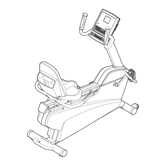
Exercise bike
Hide thumbs
Also See for COMMERCIAL VR:
- User manual (28 pages) ,
- User manual (32 pages) ,
- User manual (24 pages)
Table of Contents
Advertisement
www.nordictrack.com
Model No. NTEX13808.1
Serial No.
Write the serial number in the space
above for reference.
ACTIVATE YOUR
WARRANTY
To register your product and
activate your warranty today, go
to www.nordictrackservice.com/
registration.
CUSTOMER CARE
For service at any time, go to
www.nordictrackservice.com.
Or call 1-800-TO-BE-FIT
(1-800-862-3348)
Mon.––Fri. 6 a.m.––6 p.m. MT
Sat. 8 a.m.––4 p.m. MT
Please do not contact the store.
CAUTION
Read all precautions and instruc-
tions in this manual before using
this equipment. Keep this manual
for future reference.
Serial
Number
Decal
USER’'S MANUAL
Advertisement
Table of Contents

Related Manuals for NordicTrack COMMERCIAL VR


Summary of Contents for NordicTrack COMMERCIAL VR
- Page 1 USER’’S MANUAL Model No. NTEX13808.1 Serial No. Write the serial number in the space above for reference. Serial Number Decal ACTIVATE YOUR WARRANTY To register your product and activate your warranty today, go to www.nordictrackservice.com/ registration. CUSTOMER CARE For service at any time, go to www.nordictrackservice.com.
-
Page 2: Table Of Contents
Apply the decal in the location shown. Note: The decal(s) may not be shown at actual size. NORDICTRACK is a registered trademark of ICON IP, Inc. -
Page 3: Important Precautions
IMPORTANT PRECAUTIONS WARNING: To reduce the risk of serious injury, read all important precautions and instructions in this manual and all warnings on your exercise bike before using your exercise bike. ICON assumes no responsibility for personal injury or property damage sustained by or through the use of this product. - Page 4 STANDARD SERVICE PLANS...
-
Page 5: Before You Begin
tness, building endurance, and toning the model number and the location of the serial number body. The COMMERCIAL VR exercise bike provides decal are shown on the front cover of this manual. an impressive selection of features designed to make your workouts at home more effective and enjoyable. -
Page 6: Part Identification Chart
PART IDENTIFICATION CHART Use the drawings below to identify the small parts needed for assembly. The number in parentheses below each drawing is the key number of the part, from the PART LIST near the end of this manual. The number following the key number is the quantity needed for assembly. -
Page 7: Assembly
ASSEMBLY •• Assembly requires two persons. •• In addition to the included tool(s), assembly requires the following tool(s): •• Place all parts in a cleared area and remove the one Phillips screwdriver packing materials. Do not dispose of the packing materials until you ... - Page 8 3. While another person lifts the rear of the Frame (1), attach the Rear Stabilizer (16) to the Frame with two M10 x 96mm Bolts (65) and two M10 Locknuts (91). 4. Tip: If the Backrest Tubes (52) do not slide into the Seat Carriage (41), loosen the four M6 x 38mm Screws (25).
- Page 9 5. Tip: Do not damage the wires inside the Seat Handlebar (11) during this step. Attach the Seat Handlebar (11) to the Seat Carriage (41) with two M8 x 68mm Bolts (70), two M8 Curved Washers (86), and two M8 Locknuts (99).
-
Page 10: 93). Tip: Tighten The Two Screws In The Front
7. Attach the Seat (9) to the Seat Carriage (41) with four M6 x 16mm Screws (71) and four M6 Washers (88). Note: Only two Screws and two Washers are shown. 8. Have another person hold the Upright (2) near the Frame (1). - Page 11 10. While another person holds the Console (4) near the Upright (2), connect the console wire to the Main Wire Harness (43). Next, connect the con- sole pulse wire to the Upper Pulse Wire (42). Pulse Insert the excess wires downward into the Wire Upright (2).
- Page 12 12. Plug the Power Adapter (51) into the receptacle on the front of the exercise bike. Note: To plug the Power Adapter (51) into an outlet, see HOW TO PLUG IN THE POWER ADAPTER on page 11. 13. After the exercise bike is assembled, inspect it to make sure that it is assembled correctly and that it functions properly.
-
Page 13: To Adjust Pedal Straps/Seat
HOW TO USE THE EXERCISE BIKE HOW TO PLUG IN THE POWER ADAPTER HOW TO LEVEL THE EXERCISE BIKE IMPORTANT: If the exercise bike has been exposed If the exercise bike to cold temperatures, allow it to warm to room rocks slightly on temperature before plugging in the power adapter. - Page 14 CONSOLE DIAGRAM FEATURES OF THE CONSOLE For example, lose unwanted pounds with the 8-week Weight Loss workout. iFit workouts control the resis- The advanced console offers an array of features tance of the pedals while the voice of a personal trainer designed to make your workouts more effective and coaches you through your workouts.
-
Page 15: Manual Mode
HOW TO ACTIVATE THE CONSOLE 3. Change the resistance of the pedals as desired. The included power adapter must be used to oper- As you pedal, ate the exercise bike. See HOW TO PLUG IN THE change the resis- POWER ADAPTER on page 13. When the power tance of the pedals adapter is plugged in, the displays will turn on and the by pressing one... - Page 16 The upper When your pulse is display——This dis- detected, a ash- play can show the ing heart symbol elapsed time, the will appear in the distance that you display, and then have pedaled, your your heart rate will pedaling speed, and the approximate number of appear.
-
Page 17: To Use A Preset Workout
HOW TO USE A PRESET WORKOUT As you exercise, keep your pedaling 1. Begin pedaling or press any button on the speed near the tar- console to turn on the console. get speed for the current segment. See HOW TO ACTIVATE THE CONSOLE on At the beginning page 15. -
Page 18: To Use Ifit Workout/Sound System
HOW TO USE AN IFIT WORKOUT A moment after you select a workout, the voice of a personal trainer will begin guiding you through iFit cards are available separately. To purchase iFit your workout. cards, go to www.iFit.com or see the front cover of this manual. -
Page 19: To Change Console Settings
HOW TO CHANGE CONSOLE SETTINGS The upper display will show the currently selected backlight option. Press the Resistance increase button The console features a user mode that allows you to repeatedly to select the desired backlight option. select a unit of measurement and a backlight option for the console and to view console usage information. -
Page 20: To Adjust The Drive Belt
MAINTENANCE AND TROUBLESHOOTING Inspect and tighten all parts of the exercise bike regu- HOW TO ADJUST THE REED SWITCH larly. Replace any worn parts immediately. If the console does not display correct feedback, the To clean the exercise bike, use a damp cloth and a reed switch should be adjusted. -
Page 21: Fcc Information
FCC INFORMATION This equipment has been tested and found to comply with the limits for a Class B digital device, pursuant to part 15 of the FCC Rules. These limits are designed to provide reasonable protection against harmful interference in a residential installation. This equipment generates, uses, and can radiate radio frequency energy and, if not installed and used in accordance with the instructions, may cause harmful interference to radio communications. -
Page 22: Exercise Guidelines
EXERCISE GUIDELINES Burning Fat——To burn fat effectively, you must exer- WARNING: cise at a low intensity level for a sustained period of Before beginning this time. During the first few minutes of exercise, your or any exercise program, consult your physi- body uses carbohydrate calories for energy. - Page 23 SUGGESTED STRETCHES The correct form for several basic stretches is shown at the right. Move slowly as you stretch; never bounce. 1. Toe Touch Stretch Stand with your knees bent slightly and slowly bend forward from your hips. Allow your back and shoulders to relax as you reach down toward your toes as far as possible.
-
Page 24: Part List
PART LIST Model No. NTEX13808.1 R1112A Key No. Qty. Description Key No. Qty. Description Frame Reed Switch/Wire Upright Drive Belt Book Holder Stabilizer Cap Console Upright Grip Rail Flange Screw Adjustment Handle Power Adapter/Wire Left Handlebar Backrest Tube Backrest Resistance Rod Assembly Seat Small Spring Seat Pulse Grip/Wire... - Page 25 Key No. Qty. Description Key No. Qty. Description M10 Locknut M6 x 20mm Hex Screw Crank Cap M10 x 50mm Hex Screw M8 Split Washer M4 x 12mm Flange Screw M12 Nut M6 x 8mm Hex Screw M8 Jam Nut M3.5 x 12mm Screw Spring Washer M6 x 65mm Hex Screw...
-
Page 26: Exploded Drawing
EXPLODED DRAWING A Model No. NTEX13808.1 R1112A... - Page 27 EXPLODED DRAWING B Model No. NTEX13808.1 R1112A 59 93 57 93 59 93...
-
Page 28: Ordering Replacement Parts
ORDERING REPLACEMENT PARTS To order replacement parts, please see the front cover of this manual. To help us assist you, be prepared to provide the following information when contacting us: •• the model number and serial number of the product (see the front cover of this manual) ••...
Need help?
Do you have a question about the COMMERCIAL VR and is the answer not in the manual?
Questions and answers