Table of Contents
Advertisement
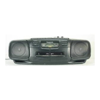
Service Manual
Portable Stereo CD System
MASH*
: SG-20W MECHANISM SERIES
TAPE DECK
TRAVERSE DECK : RAE01 13Z MECHANISM SERIES
I SPECIFICATIONS
n Radio Section
Frequency range
FM
AM
Intermediate frequency
FM
AM
Sensitivity
FM
AM
H CD Player
Sampling frequency
Decoding
Beam source
No. of channels
Less than possible measurement data
Wow and flutter
D/A converter
Panasonic"
88-108MHz
525 - 1705 kHz
10.7 MHz
455 kHz
17 dB/50 mW
(
)
-3 dB limit sens.
51
dB/m/50 mW
44.1 kHz
16 bit Iinear
Semiconductor laser
(wavelength 780 nm)
2 channel, stereo
MASH (1 bit DAC)
RX-DT30
n Tape Recorder
Track system
Recording system
Erasing system
Monitor system
Frequency range
Normal
n General
Power requirement
AC
12 V (8 "D" size, R20/LR20 batteries)
Battery
Speakers
Jacks
Output
Dimensions (W x H x D)
Weight
:
Notes
Specifications are subject to change without notice.
Weight and dimensions are approximate.
© 1995 Matsushita Electronics (S) Pte. Ltd.
All rights reserved. Unauthorized copying and
distribution is a violation of law.
ORDER NO. MD9502012C1
Radio Cassette
Colour
/
(K)
Black
Type
4 track, 2 channel, stereo
AC bias
Multi pole magnet
Variablesoundmonitor
50 - 14000 Hz
120V, 60Hz
Power consumption; 30W
10 cm (4") x 2
Headphones; 32c1
580x192 x260mm
(22'3/~s"x79/~6"x1 01/4")
15 oz.)
4.5 kg (9 lb.
without batteries
1
Advertisement
Table of Contents

Related Manuals for Panasonic RX-DT30


Summary of Contents for Panasonic RX-DT30
- Page 1 ORDER NO. MD9502012C1 Service Manual Radio Cassette Portable Stereo CD System RX-DT30 MASH* Colour Black Type : SG-20W MECHANISM SERIES TAPE DECK TRAVERSE DECK : RAE01 13Z MECHANISM SERIES I SPECIFICATIONS n Tape Recorder n Radio Section 4 track, 2 channel, stereo...
-
Page 2: Disassembly Instructions
RX-DT30 Disassembly Instructions Warning This product uses a laser diode. Refer to caution statements on page 2. ACHTUNG : Die laserernheit nicht zerlegen. Die lasereinheit darf nur gegen eine vom hersteller spezrfizierte einheit ausgetauscht werden. “ATTENTION SERVICER” Some chassis components may have sharp edges. Be careful when disassembling and servicing. - Page 3 RX-DT30 r- ~ ---~~~ - ~ ~~ - ~ ~~~ Ref. No. Removal of the Connector P.C.B. Procedure 2*31,5 CN305 ( 0 - Q ). 1. . Remove 3 screws 2. Remove 4 connectors (CN1, CN304. CN305, CN801). 3. Remove the Connector P.C.B.
- Page 4 RX-DT30 Ref. No. P.C.B. Removal of the Power Supply P.C.B. ; Removal of the Battery -I.- Procedure (0 - @ ). Remove 6 screws 1. Release claw. 21,9*10 2. Remove 1 connector (CP306) 2. Pull out the battery P.C.B. Power SUPPLY P.C.B.
- Page 5 R X - D T 3 0 1 Ref. No. 1 Removal of the Servo P.C.B. ~~~ I Procedure Removal of the flexrble cable 21,31,7 Push the top of the connector in the direction of the arrow@, and then pull out the flexrble cable in the Traverse Unit - directron of the arrowa.
- Page 6 RX-DT30 INSTALLING CASSETTE COMPARTMENT J /J-Cass. Open Spring Install the cass. open spring as shown in above diagram. Cassette Compartment 2. Fix the cassette compartment to front cabinet Release the spring INSTALLING SERVO P.C.B. Before installing the servo P.C.B., move the optical pickup toward the outer edge from the mark “A”.
- Page 7 RX-DT30 HOW TO CHECK THE TRAVERSE UNIT 1. Remove the top cabinet unit. (Refer to disassembly instructions, Fief No. 3) ( 0 - 0 ) 2. Remove 4 screws. Traverse Unit 3. Set up the traverse unit as shown in diagram.
- Page 8 RX-DT30 Terminal Guide of ICs, Transistors & Diodes AN71 35 AN7205 AN7317 AN8389SE1 AN8802SCE1 V BA1442A BA3936 BA7755A M38222M2051 MN66271 RA PST600DTA 2SB709S pmiq 2SC1684QTA 2SC2785FTA 2SJ40CDTA BN1A4MTA 2SC 1740SRTA 2SC1684RTA RVTDTC114EST 2SC1684STA *> ‘., ,,_+ ’ ,’ “,I ,/’...
-
Page 9: Schematic Diagram
RX-DT30 Schematic Diagram S E R V O C I R C U I T lC701 AN8802SCE1 V SERVO AMP... - Page 10 RX-DT...
-
Page 11: Schematic Diagram
RX-DT30 Schematic Diagram 2SC1684RTA WXHING (HIGH SPEED) a101.0102.0201.0202 ;st$OCDTA ‘JO1 D E C K 2 -R CH R E C / P t A Y “EL C H Kz.307 AN731 7 REC/PLAY Q 2 0 4 ” RIO, cto, K68oP... - Page 16 NOTES: < For MAIN & POWER SUPPLY CIRCUIT > SW301 Beatproof Switch. (I...BEATPFiOOF I, ll...BEATPROOF II) S501 AC/BatterySelect Switch.(JK501) < For DECK CIRCUIT > S601 Deck 1 Playback Switch. S602 Deck 2 Playback Switch. S603 Deck 2 Record Switch. VR601 Tape Speed Adjustment Switch.
- Page 23 RX-DT30 Terminal Function of ICs IC702 (MN66271 RA) Digital Filter / D/A Converter Servo Processor / Digital Signal Processor / Mark Mark Function Function Focus balance adjustment output FBAL BCLK Serial bit clock terminal (Not used, open) (Not used,open) TBAL...
- Page 24 RX-DT30 Function BYTCK 1 0 1 Byte clock output (Not used, open) Sub-code frame clock signal output Crystal frame clock signal output (fCLK=7.35kHz,double=l4.7kHz) Interpolation flag output (“H” interpolation) FLAG 1 0 1 Flag output (Not used, open) Spindle servo phase synchronizing signal output CLV, “L”...
- Page 25 R X - D T 3 0 IC801 (M38222M2051) System Microprocessor Function LCD bias reference voltage V2 ’ “lJ “Ll LCD bias reference voltage Vi PCNT Power control signal output IGND MUTEA AF muting control signal output KEY1 Key source input CD signal process IC control signal outpu MCLK Mode select control signal output...
- Page 26 ( R X - D T 3 0 IWO3 (Al’ 8389SEl) Tracking Coil / Traverse Motor / Spindle Motor Focus Co Function Power supply terminal I Referencevoltage input Motor driver (4) input Motor driver (3) input - Groundconnection - Groundconnection N R E S E T I Resetinput - Groundconnection...
-
Page 27: Tuner Section
RX-DT30 H Measurements and Adjustments TUNER SECTION . ALIGNMENT INSTRUCTION READ CAREFULLY BEFORE AT-TEMPTING ALIGNMENT Set XBS switch to minimum Set power source voltage to 12 V DC. Output of signal generator should be no higher than necessary Set volume control to maximum to obtain an output reading. - Page 28 1 RX-DT30 CASSETTE DECK SECTION ALIGNMENT INSTRUCTION READ CAREFULLY BEFORE Al-TEMPTING ALIGNMENT Note : No Azimuth Head Alignment is required due to Aztec Head is used in the cassette mechanism. TAPE SPEED ALIGNMENT (DECK 1,2) (Standard Value 3000 * 50 Hz . . . Deck 2)
- Page 29 RX-DT30 CD Player Section This product uses a laser diode. Refer to caution statements on page 2. Warning: is very dangerous to look or touch the laser beam. (laser radiation is invisible) Caution With the unit turned “on”, laser radiation is emitted from the pickup lens.
- Page 30 j R X - D T 3 0 n Digital Servo System DIGITAL SERVO SYSTEM This servo system has no adjustment VRs. MN66271 RA (Super 1 chip IC) (Digital servo processor) _----- - - - - - Digital audio playback + coil Lens OCUS Focus error...
- Page 32 1 R X - D T 3 0 Part Name & Description Ref No. Part No. Part Name &Description Remarks Ref No. Part No. (DECK 2) RXPOOlS PINCH ROLLER ASS’Y 245-l RMBC049 PINCH ARM SPRING IIMI RDVOOO7 MAIN BELT RBR4CY016-M RIP HEAD BRAKE SPRING RMB0109-I...
- Page 38 1 RX-DT30 Replacement Parts List Notes: * Important safety notice: Components identified by 2 mark have special characteristics important for safety. Furthermore, special parts which have purposes of fire-retardant (resistors), high-quality sound (capacitors), low noise (resistors), etc are used. When replacing any of these components, be sure to use only manufacturer’s specified parts shown in the parts list.
- Page 39 R X - D T 3 0 Part Name &Description Ref No. Part No. Remarks VARIABLE CAPACITOR 1 [Ml RCV4PCTOV 1-A VARIABLE CAPACITOR SWITCHES S501 RJJISMOZ-H SW. AC IN(JK501) I ,! SW. DECK 1 PLAYBACK S601 RSHlA013-J S602 RSHlA013-J SW, DECK 2 PLAYBACK S603 ) RSHlAOO4-1 / SW.
- Page 40 1 R X - D T 3 0 Ref No. Pact No. Part Name & Description Rem& s701 RSMOOO6-P SW, RESET OSCILLATOR x701 RSXZ16M9M02T CERAMIC OSC R J 7 0 1 ERJ8GEYOROOA l/low R J 7 0 2 ERJ8GEYOROOA l/low R J 7 0 3 ERJ8GEYOROOA l/low l/low...