Table of Contents
Advertisement
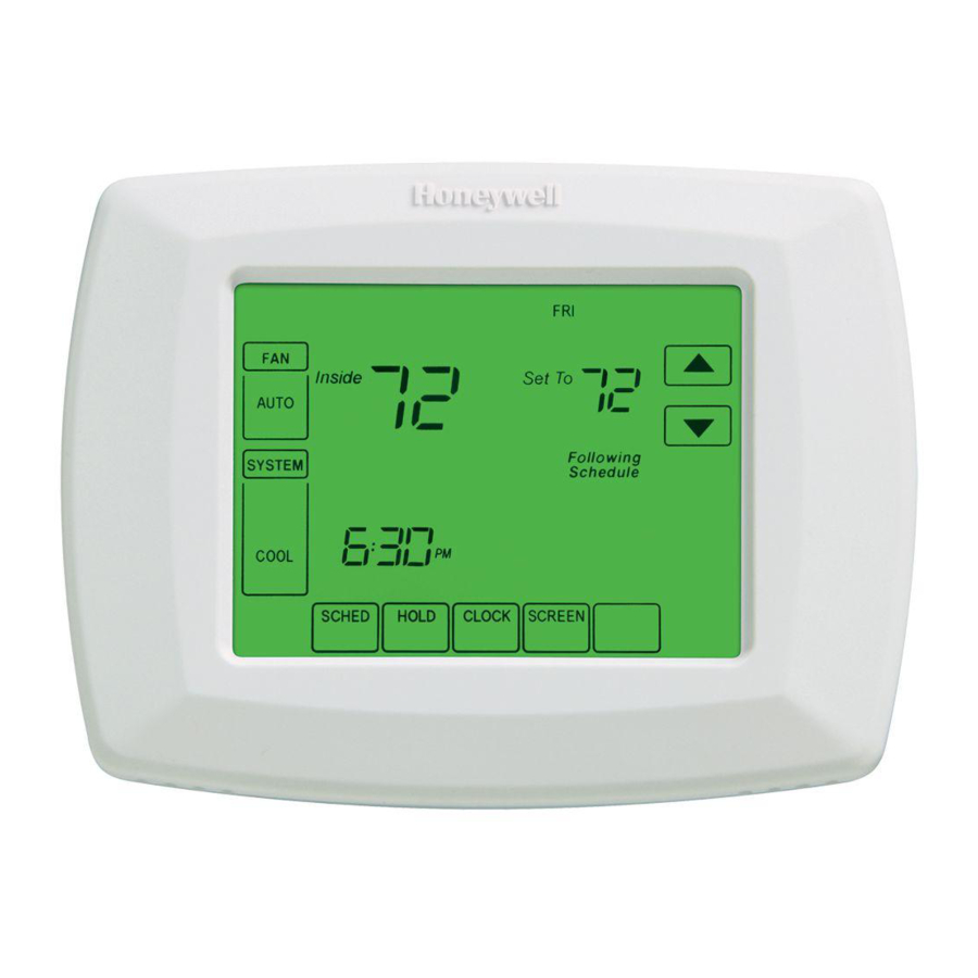
RTH8500D Touch Screen
Programmable Thermostat
The RTH8500D Thermostat provides electronic control of 24 Vac heating and
cooling systems or 750 mV heating systems.
For assistance with your Honeywell product, please visit
www.honeywell.com/yourhome or call Honeywell Customer Care
toll free at 1-800-468-1502.
U.S. Pat. 6,595,430
Other Patents Pending
® U.S. Registered Trademark
© 2004 Honeywell International Inc.
All Rights Reserved
Read and Save these Instructions
OWNER'S GUIDE
69-1725-1
Advertisement
Table of Contents

Related Manuals for Honeywell RTH8500D


Summary of Contents for Honeywell RTH8500D
-
Page 1: Programmable Thermostat
RTH8500D Touch Screen Programmable Thermostat The RTH8500D Thermostat provides electronic control of 24 Vac heating and cooling systems or 750 mV heating systems. For assistance with your Honeywell product, please visit www.honeywell.com/yourhome or call Honeywell Customer Care toll free at 1-800-468-1502. -
Page 2: Table Of Contents
Attach New Thermostat to Wallplate... 23 Set the Calendar... 24 Configure Installer Setup ... 26 Get to Know Your Thermostat Display... 38 Set System Setting ... 40 Program Your Heating and Cooling Schedule ... 42 Cancel a Schedule Period ... 46 Set Time ... -
Page 3: Prepare For Installation
TURN OFF POWER to system at the furnace, or at the fuse/circuit breaker panel before you begin. Match the letter of your old thermostat wire with the terminal of the corresponding letter on your new thermostat or base. de la letra correspondiente de... - Page 4 Step 1. Prepare for Installation (Cont) 2. Check that you have everything required for the installation: • Three AAA alkaline batteries • No. 2 Phillips screwdriver and standard pocket screwdriver • Drill • Drill bit — use 3/16 in. for drywall; use 7/32 in. for plaster •...
-
Page 5: Follow Important Instructions
Step 2. Follow Important Instructions 1. Do not connect the wires to the new thermostat based on wire color because damage can occur to the heating and/or cooling system. These Installation Instructions explain later how to use the enclosed wire labels to correctly mark the wires connected to your old thermostat. -
Page 6: Remove Old Thermostat
1. Turn off power at the heating and/or cooling system or fuse/circuit breaker panel. 2. Remove the cover from the old thermostat. 3. Remove the old thermostat from the wall or wallplate. Do not remove the wires. MERCURY NOTICE If you are replacing a thermostat that contains mercury in a sealed tube, do not place your old thermostat in the trash. -
Page 7: Follow Special Instructions
Step 4. Follow Special Instructions 1. If you have two C and/or C1 wires connected to your old thermostat, do not connect them to your new thermostat. 2. Disconnect the C and/or C1 wires. Make sure they do not touch each other or any other wires. - Page 8 Step 4. Follow Special Instructions (Cont) 4. If you have only one C and/or C1 wire connected to your old thermostat, connect this wire to C on the new thermostat. Visit www.honeywell.com/yourhome or call Honeywell Customer Care at 1-800-468-1502 before returning the thermostat to the store.
- Page 9 Step 4. Follow Special Instructions (Cont) 5. If you find any wires not connected to your old thermostat, do not connect them to your new thermostat. 6. Wrap the end of the wires that are not connected with electrical tape.
-
Page 10: Label Old Thermostat Wires
Do not allow the wires to fall into the wall opening after the wires are disconnected. 2. Remove any remaining part of the old thermostat from the wall. OLD THERMOSTAT When connecting the wires to the new thermostat, refer to the wire labels. -
Page 11: Mount New Wallplate To Wall
Step 6. Mount New Wallplate to Wall 1. Separate the wallplate from the thermostat as shown. WALLPLATE WIRE HOLE THERMOSTAT M22202 69-1725-1... - Page 12 Step 6. Mount New Wallplate to Wall (Cont) 2. Pass the labeled wires through the wire hole on the wallplate. WALL OPENING WIRE HOLE WALLPLATE LABELED WIRES M22203 69-1725-1...
- Page 13 Step 6. Mount New Wallplate to Wall (Cont) 3. Position the wallplate on the wall with the arrow pointing up. Level the wallplate (for appearance only) and mark the two mounting holes with a pencil. LEVEL WALLPLATE M22204 PLACE LEVEL ON SUPPORT TABS MARK MOUNTING...
- Page 14 Step 6. Mount New Wallplate to Wall (Cont) 4. Move the wallplate aside and drill holes at the locations marked on the wall. Drill 3/16 in. holes for drywall or 7/32 in. holes for plaster. 5. Tap the wall anchors into the drilled holes until even with the wall surface.
-
Page 15: Connect Wires To New Wallplate
If you have a standard heating and/or cooling system, use the CONVENTIONAL letter designations. If you have a heat pump system, use the HEAT PUMP letter designations to wire the new thermostat. WALLPLATE 3. If wires are to be connected to both Rc and R, loosen the Rc and R screw terminals and remove the metal jumper wire. - Page 16 Step 7. Connect Wires to New Wallplate (Cont) 5. Loosen the screw terminals. Insert the labeled wires into the holes on the side of the terminal block that match the letter designations. Tighten the screw terminals. 6. If any of the labeled wires do not match the letter designations, see next page for wire connections.
- Page 17 System. Use the information on page 20 if you are wiring a Heat Pump System. CONVENTIONAL letter designations on the new thermostat Do not connect more than one wire to each terminal. Be sure to read the notes referenced in the numbered triangles above. These numbered notes appear on the next page.
- Page 18 Connect the old R to the new R to the new R. If two C and/or C1 wires were connected to the old thermostat, do not connect them to the new thermostat. Wrap the bare end of each wire separately with electrical tape and do not use.
- Page 19 X or B, F or X2 or X, AUX, W1, W or Be sure to read the note referenced in the numbered triangles above. These numbered notes appear on the next page. HEAT PUMP letter designations on the new thermostat M22210 69-1725-1...
- Page 20 Call your local heating and cooling contractor for assistance. If the old thermostat had wires on both O and B, be sure to attach the B wire to the C letter designation on the new thermostat.
- Page 21 Step 7. Connect Wires to New Wallplate (Cont) 9. Push excess wire back into the wall opening. Keep wires in the shaded area. WIRE WALLPLATE WALL OPENING SHADED AREA M22211 69-1725-1...
-
Page 22: Install Batteries
1. Install three fresh AAA alkaline batteries on the back of the thermostat as marked on the thermostat. BATTERIES 2. Remove the tab labeled “Remove during installation” in the lower right corner of the thermostat back. REMOVE 69-1725-1 Step 8. Install Batteries... -
Page 23: Attach New Thermostat To Wallplate
WALLPLATE TERMINAL SCREW BLOCK 2. Push the thermostat straight onto the wallplate until it snaps into place. 3. Turn on the power at the heating and/or cooling system or fuse/ circuit breaker panel. If the wires interfere with mounting the thermostat to the wallplate, push the excess wire back into the wall opening. -
Page 24: Set The Calendar
This thermostat is designed to automatically keep current time and day in memory for up to ten years, under normal use, once the calendar is set. When the thermostat is first powered, the display is ready to set the calendar. - Page 25 Step 10. Set the Calendar (Cont) 3. Use the arrow keys to set the current time. 4. Press the Done key. ARROWS TO SET TIME SAT A A T DONE M22227 69-1725-1...
-
Page 26: Configure Installer Setup
Step 11. Configure Installer Setup 1. Use the Installer Setup Menu to match your new thermostat to your heating and/or cooling system. Follow the steps in this section to set up your thermostat. 2. Press and release the System key. - Page 27 Step 11. Configure Installer Setup (Cont) 3. Press and hold the center blank key for approximately five seconds, until the screen changes. 4. Release the center key when the display on your thermostat matches the display below. CHANGE FILTER UV LAMP HUMIDIFIER PAD...
- Page 28 11. Configure Installer Setup (Cont) 5. Press the Up or Down arrows to the right of the two-digit number in the lower right corner of the screen to select your setting for Installer Setup Number 0120 below. 6. After you select your setting, press the Up arrow key to the right of 0120 to go to the next Installer Setup Number.
- Page 29 4 - Heat Only with fan (Conventional) -- Gas, oil or electric heating without central air conditioning. Typically wires are R, W and G on new thermostat. 5 - Hot Water Heat Only (Conventional) -- Gas or Oil hot water heat with three wires connected to new thermostat or for normally open hot water valves with wires connected to R and Y on new thermostat.
- Page 30 Installer (Select Your Setting) Setup Name 0 - Gas or Oil Heat -- Heating system controls fan in a call for heat. 1 - Electric Heat -- Thermostat controls fan in a call for heat. SETTING ARROW DOWN ARROW Settings...
- Page 31 Step 11. Configure Installer Setup (Cont) 13. If you do not have a number 0190 on the left side of your display, go to the next page. 14. If you have a number 0190 on the left side of your display, press the Up or Down arrow to select your setting for Installer Setup Number 0190.
- Page 32 Step 11. Configure Installer Setup (Cont) 16. If you do not have a number 0240 on the left side of your display, go to the next page. 17. If you have a number 0240 on the left side of your display, press the Up or Down arrow to select your setting for Installer Setup Number 0240.
- Page 33 Step 11. Configure Installer Setup (Cont) 19. Press the Up or Down arrow to select your setting for Installer Setup Number 0320. 20. After you select your setting, press the Up arrow to go to the next Installer Setup Number. ARROW INSTALLER SETUP...
- Page 34 Step 11. Configure Installer Setup (Cont) 21. Press the Up or Down arrow to select your setting for Installer Setup Number 0330. 22. After you select your setting, press the Up arrow to go to the next Installer Setup Number. ARROW INSTALLER SETUP...
- Page 35 Step 11. Configure Installer Setup (Cont) 23. Press the Up or Down arrow to select your setting for Installer Setup Number 0500. 24. After you select your setting, press the Up arrow to go to the next Installer Setup Number. ARROW INSTALLER SETUP...
- Page 36 Step 11. Configure Installer Setup (Cont) 25. Press the Up or Down arrow to select your setting for Installer Setup Number 0530. 26. After you select your setting, press the Up arrow to go to the next Installer Setup Number. ARROW INSTALLER SETUP...
- Page 37 27. Press the Up or Down arrow to select your setting for Installer Setup Number 0640. 28. After you select your setting, press the Done key to exit the Installer Setup and save your settings. 29. Congratulations! The installation of the thermostat is complete. ARROW INSTALLER SETUP...
-
Page 38: Get To Know Your Thermostat Display
Get to Know Your Thermostat Display Thermostat SYSTEM SELECTS EM. HEAT/HEAT/OFF/COOL SELECTS ON/AUTO AUTO SYSTEM HEAT SCHED ENTERS SCHEDULING MODE HOLD SETS A PERMANENT HOLD AND ACTIVITIES VACATION HOLD 69-1725-1 Inside Set To SCHED HOLD CLOCK SCREEN CLOCK SETS THE... - Page 39 Get to Know Your Thermostat Display (Cont) Display SHOWS CURRENT DAY OF THE WEEK SHOWS FAN SETTING Inside AUTO SYSTEM HEAT SYSTEM SHOWS CURRENT SYSTEM POSITION INSIDE TEMPERATURE SHOWS THE CURRENT INSIDE TEMPERATURE Set To SCHED HOLD CLOCK SCREEN TIME...
-
Page 40: Set System Setting
Off—Both the heating and cooling systems are off. Cool—Thermostat controls the cooling system. Em. Heat (Heat Pump Systems with Auxiliary Heat)— Thermostat controls emergency heat and auxiliary heat, if needed. Heat Pump compressor is not operational. CAUTION Equipment Damage Hazard. - Page 41 Set System Setting (Cont) Set Fan Setting Press the Fan button to select Auto or On: Auto—Normal setting for most homes. The fan runs only when the heating or cooling system is on. On—The fan runs continuously. Use this setting for improved air circulation or for more efficient air cleaning.
-
Page 42: Program Your Heating And Cooling Schedule
Program Your Heating and Cooling Schedule Your thermostat can control up to four different schedule periods per day: Wake—Period when you awaken and want your home at a comfortable temperature. Leave—Period when you are away from home and want an energy- saving temperature. - Page 43 Program Your Heating and Cooling Schedule (Cont) 2. Press Edit key. OK TO PICK MULTIPLE DAYS Inside AUTO SYSTEM EM HEAT HEAT COOL AUTO SCHED SCHED DONE EDIT SCREEN LOCKED Set To CANCEL PERIOD HOLD HOLD CLOCK SCREEN WAKE LEAVE RETURN HEAT Following...
- Page 44 Program Your Heating and Cooling Schedule (Cont) 3. It is OK to pick multiple days. Select any combination of days to edit. These days are scheduled with the same times and temperatures. Check marks appear next to days selected. OK TO PICK MULTIPLE DAYS AUTO CIRC DONE...
- Page 45 Program Your Heating and Cooling Schedule (Cont) 9. When complete, press Done key. “Saving Changes” appears on the screen to indicate changes are being saved to the day(s) modified. 10. To set a Program Schedule for the remaining days of the week, repeat steps 1-9.
-
Page 46: Cancel A Schedule Period
NOTE: You may want to cancel a period to match your lifestyle; for example, if someone is always home during the day on Tuesday, you can cancel the Leave and Return periods (the thermostat would then control to the Wake temperature until the Sleep period). 1. Press Sched key. -
Page 47: Set Time
Set Time 1. Press Clock. 2. Use the arrows to set the current time. DONE 3. Press the Done key. The current day of the week should already be set correctly. If not, see Step 11, Configure Installer Setup. Set Time CANCEL M19958 69-1725-1... -
Page 48: Set Temperature Overrides
The Hold Temperature Until time defaults to the start time of the next scheduled period. 2. Press the Up or Down arrow next to the Time key to set the desired time for the thermostat to resume the schedule. Inside AUTO... - Page 49 Set Temperature Overrides (Cont) Permanent Hold Permanent Hold changes the temperature setting until Permanent Hold is cancelled. 1. Press the Hold key. “Permanent Hold” appears on the screen. 2. Press the Up or Down arrow next to the temperature you want to set during “Hold.”...
- Page 50 2. Press the Hold key twice. Screen shows “Hold Temperature Until” 1 day. 3. Press the Up and Down arrow keys to change the number of Days you desire the thermostat to override the schedule. Inside AUTO SYSTEM...
-
Page 51: Clean Your Thermostat Screen
Clean Your Thermostat Screen 1. Press the Screen key. The thermostat locks out all touch keys for 30 seconds to allow for cleaning. 2. Use a damp cloth slightly moistened with water or household glass cleaner to clean the screen. -
Page 52: Use Your Filter Timer
The Filter Timer notifies you when to change your furnace filter. Reset Filter Timer 1. “Change Filter” appears on the screen when the filter timer expires. 2. Press the Reset key to restart the filter timer. OK TO PICK MULTIPLE DAYS SCREEN LOCKED CHANGE FILTER AUTO SYSTEM... -
Page 53: Understanding Temperature Recovery Feature
For example—you get out of bed at 6:00 AM and want the temper-ature to be 70°F. Set the Wake period for 6:00 AM and 70°F. The thermostat then turns on the heat before 6:00 AM to raise the temperature to 70°F by 6:00 AM. -
Page 54: Replace Batteries
Replace Batteries 1. When the LO Battery indicator is flashing, replace the batteries promptly with three fresh AAA alkaline batteries M19963 2. Remove thermostat from the wallplate by pulling straight out. WALL M22243 69-1725-1... - Page 55 Replace Batteries (Cont) 3. Remove the old batteries and insert three fresh AAA alkaline batteries, as marked on the thermostat. BACK OF THERMOSTAT + + + BATTERIES M22212 69-1725-1...
- Page 56 4. Align the screw blocks with the pins on the back of the thermostat. TERMINAL SCREW BLOCK 5. Push the thermostat straight onto the wallplate until it snaps into place. 69-1725-1 Replace Batteries (Cont) WALLPLATE PINS ON BACK OF THERMOSTAT...
-
Page 57: Review Battery Tips
2. Always use fresh AAA alkaline batteries. Non-alkaline batteries do not last as long and can leak, causing thermostat damage. 3. Although the thermostat has a Low Battery indicator, replace the batteries once a year to prevent the thermostat and heating/ cooling system from shutting down due to lack of battery power. -
Page 58: Built-In Compressor Protection
Built-in Compressor Protection The RTH8500D Thermostat has built-in compressor protection (minimum-off timer) that prevents the compressor from restarting too early after a shutdown. The minimum-off timer is activated after the compressor turns off. If there is a call during the minimum-off timer, the thermostat shows “Wait”... -
Page 59: Troubleshooting Tips
Furnace Filter Change Reminder. See Installer Setup Number 0500 in Step 11. Check that fresh AAA alkaline batteries are installed as marked on the thermostat. Check that the temperature settings are: • Heating 40°F to 90°F(4.5°C to 32°C). - Page 60 Troubleshooting Tips (Continued) If . . . Cannot set System setting to Cool. “Heat On” is not shown in the display. “Cool On” is not shown in the display. “Wait” shows in the display. Fan does not turn on in a call for heat (electric furnaces only).
- Page 61 Cooling System Type, and make sure the setting matches the installed heating and/ or cooling system. A system monitor is wired to the thermostat L terminal. See Heating or Cooling system does not turn on in the Troubleshooting Tips.
-
Page 62: Customer Assistance
Customer Assistance For assistance with your Honeywell product, please visit www.honeywell.com/yourhome or call Honeywell Customer Care toll free at 1-800-468-1502. 69-1725-1... -
Page 63: Limited One-Year Warranty
This warranty does not cover removal or reinstallation costs. This warranty shall not apply if it is shown by Honeywell that the defect or malfunction was caused by damage which occurred while the product was in the possession of a consumer. - Page 64 Automation and Control Solutions Honeywell International Inc. 1985 Douglas Drive North Golden Valley, MN 55422 69-1725-1 G.H. Rev. 10-04 Honeywell Limited-Honeywell Limitée 35 Dynamic Drive Scarborough, Ontario M1V 4Z9 www.honeywell.com/yourhome...
Need help?
Do you have a question about the RTH8500D and is the answer not in the manual?
Questions and answers