Advertisement
Quick Links
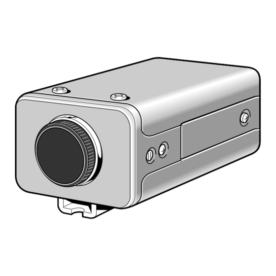
SERVICE MANUAL
B/W CCD Camera
SPECIFICATIONS
Scanning system : CCIR standard (625 TV lines, 25 frames/sec.)
Interlace : PLL 2:1 interlace
Image device : 1/2 inch solid state image device CCD
Picture elements : 795 (Horizontal) x 596 (Vertical)
Effective picture elements : 752 (Horizontal) x 582 (Vertical)
Synchronizing system : Line lock/External sync (automatic switching)
Resolution : 560 TV lines horizontally, 350 TV lines vertically
Video output level : 1.0 Vp-p/75 W , composite
Video S/N ratio : More than 50 dB
Minimum required illumination : Approx. 0.02 lux with a F 1.2 lens,
(incandescent lighting)
Backlight compensation : Manual ON/OFF switching, zone light measuring system
(Active when using an auto-iris lens)
Electronic iris function : Manual ON/OFF switching
Electronic iris range : 0.02 lux to 10,000 lux (F1.2, lens)
0.03 lux to 15,000 lux (F1.4, lens)
Flange-back : 12.5 mm ± 0.8 mm
Gamma correction : g = 0.45
Lens mount : CS mount (or C mount with the supplied adaptor)
Environmental conditions : Temperature: -10 °C ~ + 50 °C
Humidity: less than 90 % (no condensation)
Power supply : 24 V AC, (±4 V) 50 Hz
Power consumption : 3.1 W (with auto iris lens)
2.4 W (without auto iris lens)
Weight : Approx. 330 g (without lens)
The components designated by a symbol ( ! ) in this schematic diagram designates components whose value are of
special significance to product safety. Should any component designated by a symbol need to be replaced, use only the
part designated in the Parts List. Do not deviate from the resistance, wattage, and voltage ratings shown.
NOTE : 1. Parts order must contain model number, part number, and description.
2. Substitute parts may be supplied as the service parts.
3. N. S. P. : Not available as service parts.
Design and specification are subject to change without notice.
L72H4/XE
Approx. 0.03 lux with a F 1.4 lens
PRODUCT SAFETY NOTICE
FILE NO.
VCB-3574IRP
(Product Code : 117 061 24)
(South East Asia)
(Europe)
CONTENTS
DISASSEMBLY, ADJUSTMENT, PARTS LIST.....FILE1
CIRCUIT DIAGRAMS
OVERALL WIRING, CA-1 CIRCUIT ...........FILE2
CA-2 CIRCUIT ............................................FILE3
CA-3 CIRCUIT ............................................FILE4
CA-4 CIRCUIT ............................................FILE5
CA-5 CIRCUIT ............................................FILE6
REFERENCE No. SM5310037
Advertisement

Related Manuals for Sanyo VCB-3574IRP


Summary of Contents for Sanyo VCB-3574IRP
-
Page 1: Service Manual
FILE NO. SERVICE MANUAL B/W CCD Camera VCB-3574IRP (Product Code : 117 061 24) SPECIFICATIONS (South East Asia) (Europe) Scanning system : CCIR standard (625 TV lines, 25 frames/sec.) Interlace : PLL 2:1 interlace Image device : 1/2 inch solid state image device CCD... - Page 2 FILE NO. SERVICE MANUAL B/W CCD Camera VCB-3574IRP (Product Code : 117 061 24) SPECIFICATIONS (South East Asia) (Europe) Scanning system : CCIR standard (625 TV lines, 25 frames/sec.) Interlace : PLL 2:1 interlace Image device : 1/2 inch solid state image device CCD...
-
Page 3: Disassembly
1. DISASSEMBLY 3. Remove the two screws, and then pull out the top cabinet. 2. Remove the rear panel. 5. Remove the front panel. 1. Loosen the two screws, and then remove the left and right side panels. 4. Remove the two screws, and then remove the bracket and pull out the bottom cabinet. -
Page 4: Board Location
2. BOARD LOCATION TP102 TP101 Abbr. TP301 Abbr. CT301 CA-1 board (Side A) TP201 CA-3 board (Side A) VR201 VR401 TP202 SW401 VR204 VR203 SW402 CN206 SW403 CA-2 board (Side B) CA-4 board (Side A) VR502 CA-2 board CA-3 board CA-5 board CA-4 board VR501... -
Page 5: Adjustment
3. ADJUSTMENT 3-1. ADJUSTMENT PREPARATION 3-4. SUB Voltage Adjustment Adjustment location: VR201 (CA-2) 1. Set the ITE gray scale chart II( =0.45) to the viewer. Measuring location: TP102 (CA-1) 2. Set the angle of adjustment control (VR) before starting Measuring equipment: Digital voltmeter adjustment at the center or temporary adjustment (nearly Subject: No designation adjusted) unless specified. - Page 6 3-6. Auto Iris Level Adjustment 3-8. Line Phase Adjustment Adjustment location: SW401, SW402, VR401 (CA-4) Adjustment location: VR502 (CA-5) Measuring location: VIDEO OUT Measuring location: VIDEO OUT, 24 V AC terminals Measuring equipment: Oscilloscope Measuring equipment: Oscilloscope Subject: Gray scale chart Subject: Gray scale chart Preparation: Preparation:...
-
Page 7: Parts List
4. PARTS LIST LOCATION PARTS NO. DESCRIPTION LOCATION PARTS NO. DESCRIPTION 613 186 2524 COMPL PWB,CA-3 CABINET & CHASSIS PARTS 613 185 4413 COMPL PWB,CA-4 613 159 9369 DEC INDICATOR 411 021 0809 SCR S-TPG BIN 2X6 613 156 4015 COVER BOTTOM 613 185 4383 COMPL PWB,CA-1... - Page 8 ELECTRICAL PARTS Note: 1. Materials of Capacitors and Resistors are abbreviated as follows ; Resistors Capacitors MT-FILM Metallized Film Resistor MT-POLYEST Metallized Polyester Capacitor MT-GLAZE Metallized Glaze Resistor MT-COMPO Metallized Composite Capacitor OXIDE-MT Oxide Metallized Film Resistor TA-SOLD Tantalum Solid Capacitor AL-SOLID Aluminum Solid Capacitor NP-ELECT...
- Page 9 LOCATION PARTS NO. DESCRIPTION LOCATION PARTS NO. DESCRIPTION C2008 403 258 4200 ELECT 22U M 6.3V R2043 401 105 4205 MT-GLAZE 33K JA 1/16W C2012 403 164 0204 CERAMIC 0.1U Z 25V R2044 401 105 6001 MT-GLAZE 5.6K JA 1/16W C2013 403 276 7405 TA-SOLID...
- Page 10 LOCATION PARTS NO. DESCRIPTION LOCATION PARTS NO. DESCRIPTION C3019 403 113 3805 CERAMIC 1000P K 50V (RESISTORS) C3020 403 164 0204 CERAMIC 0.1U Z 25V R4005 401 037 5400 MT-GLAZE 1K JA 1/10W C3021 403 113 3805 CERAMIC 1000P K 50V R4006 401 038 6406 MT-GLAZE 4.7K JA 1/10W...
- Page 11 LOCATION PARTS NO. DESCRIPTION LOCATION PARTS NO. DESCRIPTION C5002 403 069 5601 CERAMIC 0.01U K 50V ACCESSORIES C5003 403 345 6100 ELECT 47U M 25V 9001 636 009 7841 LENS CAP C5004 403 337 6002 ELECT 10U M 35V 9102 613 186 2906 INSTRUCTION MANUAL C5005...
- Page 12 SANYO Electric Co., Ltd. Osaka, Japan May/’99/1200 MI Printed in Japan...
- Page 13 VCB-3574IRP BLOCK DIAGRAMS,CIRCUIT DIAGRAMS & PRINTED WIRING BOARDS TABLE OF CONTENTS Page OVERALL WIRING CA-1 CIRCUIT CA-1 CIRCUIT WAVEFORMS CA-1 BOARD (SIDE A & B) CA-2 CIRCUIT CA-2 BOARD (SIDE A & B) IC203 BLOCK DIAGRAM CA-2 CIRCUIT WAVEFORMS CA-3 CIRCUIT CA-3 BOARD (SIDE A &...