Table of Contents
Advertisement
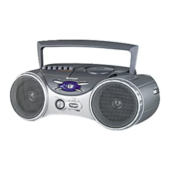
Illustration: QT-CD210
IMPORTANT SERVICE NOTES (FOR QT-CD210 ONLY) ............................................................................................... 2
SPECIFICATIONS ............................................................................................................................................................. 2
NAMES OF PARTS ........................................................................................................................................................... 3
FITTING OF DIAL POINTER ............................................................................................................................................. 3
DISASSEMBLY .................................................................................................................................................................. 4
REMOVING AND REINSTALLING THE MAIN PARTS ..................................................................................................... 4
ADJUSTMENT ................................................................................................................................................................... 6
SCHEMATIC DIAGRAM .................................................................................................................................................... 8
WIRING SIDE OF P.W.BOARD ....................................................................................................................................... 10
NOTES ON SCHEMATIC DIAGRAM .............................................................................................................................. 12
TYPES OF TRANSISTOR ............................................................................................................................................... 12
WAVEFORMS OF CD CIRCUIT ...................................................................................................................................... 13
TROUBLESHOOTING (CD SECTION) ........................................................................................................................... 14
FUNCTION TABLE OF IC ................................................................................................................................................ 18
PARTS GUIDE/EXPLODED VIEW
SERVICE MANUAL
CONTENTS
SHARP CORPORATION
- 1 -
QT-CD210(BL)
QT-CD210(S)
QT-CD210(WH)
QT-CD210C(S)
• In the interests of user-safety the set should be restored to its
original condition and only parts identical to those specified should
be used.
This document has been published to be used
for after sales service only.
The contents are subject to change without notice.
QT-CD210/C
No. SY964QTCD210/
Page
Advertisement
Table of Contents

Related Manuals for Sharp QT-CD210


Summary of Contents for Sharp QT-CD210
-
Page 1: Table Of Contents
• In the interests of user-safety the set should be restored to its original condition and only parts identical to those specified should be used. CONTENTS Page IMPORTANT SERVICE NOTES (FOR QT-CD210 ONLY) ....................2 SPECIFICATIONS ................................2 NAMES OF PARTS ................................3 FITTING OF DIAL POINTER ............................. 3 DISASSEMBLY .................................. 4 REMOVING AND REINSTALLING THE MAIN PARTS ..................... -
Page 2: Important Service Notes (For Qt-Cd210 Only)
QT-CD210/C FOR A COMPLETE DESCRIPTION OF THE OPERATION OF THIS UNIT, PLEASE REFER TO THE OPERATION MANUAL. IMPORTANT SERVICE NOTES (FOR QT-CD210 ONLY) BEFORE RETURNING THE AUDIO PRODUCT (Fire & Shock Hazard) Before returning the audio product to the user, perform the following safety checks. -
Page 3: Names Of Parts
QT-CD210/C NAMES OF PARTS (TAPE) Record Button 1 2 3 4 5 6 (TAPE) Play Button (TAPE) Rewind Button (TAPE) Fast Forward Button (TAPE) Stop/Eject Button (TAPE) Pause Button Cassette Compartment CD Compartment Tuning Control 13 14 (CD) Stop Button... -
Page 4: Disassembly
QT-CD210/C DISASSEMBLY Caution on Disassembly (C3)x1 ø2.5x8mm Follow the below-mentioned notes when disassembling the unit and reassembling it, to keep it safe and ensure excellent performance: CD Lid (C2)x7 Switch 1. Take cassette tape and compact disc out of the unit. - Page 5 QT-CD210/C TAPE MECHANISM SECTION Hook (A1) x1 Perform steps 1 to 5 of the disassembly method to remove the ø2x7mm (A2)x2 tape mechanism. (See page 4.) (A1) x1 ø2x3mm How to remove the record / playback and erase Record/Playback Erase Head heads (See Fig.
-
Page 6: Adjustment
QT-CD210/C ADJUSTMENT MECHANISM SECTION • Driving Force Check • AM IF/RF Torque Meter Specified Value Test Stage Instrument Specified Connection Value/Adjusting PLAY: TW-2412 Over 120 g Point • Torque Check AM IF Input: Antenna Output: Pin 18 of IC1 Torque Meter... -
Page 7: Test Mode
QT-CD210/C CD SECTION Since this CD system incorporates the following automatic adjustment function, when the pickup is replaced, it is not necessary to reajust it. Since this CD unit does not need adjustment, the combination of PWB and laser pickup unit is not restricted. -
Page 8: Schematic Diagram
QT-CD210/C ( ): CD STOP MAIN PWB-A1 C825 3.72V R801 1.87V 47/16 (5.0V) (1.45V) Q801 PICK-UP UNIT KTA1266 GR C815 C816 C817 IC801 SWITCHING 47/16 0.022 2.97V 100/10 VOLTAGE VOLTAGE (4.39V) IC801 C826 4.84V 2.86V(0.99V) SERVO PRE AMP. C802 2.04V 2.12V... - Page 9 QT-CD210/C C825 47/16 C823 0.022 R824 C826 49 48 47 46 45 44 43 42 41 40 38 37 36 35 34 33 32 31 R820 R826 2.08V SW810 220K (0V) CD LID R827 C827 R821 LPFN PUSEL2 0.015(ML) LPFO 4.97V...
-
Page 10: Wiring Side Of P.w.board
QT-CD210/C SPEAKERS SP201 SP202 L-CH R-CH CNP101 1 2 3 4 REC. PLAY SW102 C351 RECORD/ PLAYBACK R354 E C B Q351 R351 R353 L301 C352 C353 C354 IC101 R352 1 3 5 7 9 2 4 6 8 CNS201... - Page 11 QT-CD210/C TAPE ERASE HEAD RECORD/PLAYBACK (240-5) HEAD(240-4) SW601 M601 TAPE MAIN TAPE MOTOR (240-7) (240-6) CNS101 (230) T651 BATTERYS POWER TRANSFORMER DC9 V [ "D" size(UM/SUM-1, R20 or HP2) battery x 6 ] (229) C652 C653 D653 D652 D654 SO651...
-
Page 12: Notes On Schematic Diagram
QT-CD210/C NOTES ON SCHEMATIC DIAGRAM • Resistor: 1. Tuner To differentiate the units of resistors, the symbol as K and M ( ): AM mode are used: the symbol K means 1000 ohm and the symbol M Marking except for ( ): FM mode means 1000 kohm and the resistor without any symbol is an 2. -
Page 13: Waveforms Of Cd Circuit
QT-CD210/C WAVEFORMS OF CD CIRCUIT NO DISC FOCUS SEARCH STOP PLAY TMAX IC802 66pin IC802 50pin SBOK IC803 20pin IC802 45pin IC802 72pin IC803 21pin FOCUS SEARCH TOC IL STOP PLAY IC802 74pin IC802 64pin IC802 62pin IC802 67pin IC802 64pin... -
Page 14: Troubleshooting (Cd Section)
QT-CD210/C TROUBLESHOOTING (CD SECTION) When the CD does not function When the CD section does not operate when the objective lens of the optical pickup is dirty, this section may not operate. Clean the objective lens, and check the playback operation. When this section does not operate even after the above step is taken,check the following items. - Page 15 QT-CD210/C • Laser failure. Is +5V applied to the emiter of Q204 ? Check the PWB pattern of Q204. Check the peripheral parts of IC803 and Q204. Is +5V applied to the collector of Q204 ? Check the PWB pattern between collector of Q204 and pin 75 of Is +5V applied to the pin 75 (VDD) of IC802 ? IC802.
- Page 16 QT-CD210/C • Focus servo sawtooth wave failure. IC802 is faulty. Is sawtooh wave output to the pin 66 (FOO) of IC802 ? 1.5~2.5sec Check the PWB pattern of IC803. Is +8.1V applied to the pins 1 and 30 (VCC) of IC803 ? Check the PWB pattern of IC803.
- Page 17 QT-CD210/C • Track search failure Does the sled motor run in FF/REW state when the CD Check as stated in item "SLED MOTOR OPERATION FAILURE". TEST MODE is set? Is the following wave output to the pin 67 (TRO) of IC802 IC802 failure.
-
Page 18: Function Table Of Ic
QT-CD210/C FUNCTION TABLE OF IC IC802 VHiTC9457F0-1: Servo/Signal Control (TC9457F0) (1/4) Pin No. Port Name Terminal Name Input/Output Function (OT5)S1 SEG1 Output Segment signal output to the LCD panel. (OT6)S2 SEG2 Output Up to 72 segments in a matrix with COM1 to COM4 can be displayed. - Page 19 QT-CD210/C IC802 VHiTC9457F0-1: Servo/Signal Control (TC9457F0) (2/4) Pin No. Port Name Terminal Name Input/Output Function (S12)P4-1 PUSEL2 Input 3-bit CMOS I/O ports. (SO/S11/ Input/Output These ports can be set for input or output bit for bit by a program. SDA)P4-2...
- Page 20 QT-CD210/C IC802 VHiTC9457F0-1: Servo/Signal Control (TC9457F0) (3/4) Pin No. Port Name Terminal Name Input/Output Function SBAD SBAD Input/Output Subbeam add signal input pin. Input/Output Tracking error input pin. This input is read when tracking servo is on. TEZI TEZI Input/Output Tracking error zero-cross input pin.
- Page 21 QT-CD210/C IC802 VHiTC9457F0-1: Servo/Signal Control (TC9457F0) (4/4) Pin No. Port Name Terminal Name Input/Output Function /HOLD RYNCREC Input This pin is used to input a signal that requests or clears the hold mode. Normally, use this pin for CD mode select signal input or battery detection signal input.
- Page 22 QT-CD210/C — M E M O — – 22 –...
- Page 23 “HOW TO ORDER REPLACEMENT PARTS” To have your order filled promptly and correctly, please furnish the For U.S.A. only following information. Contact your nearest SHARP Parts Distributor to order. 1. MODEL NUMBER 2. REF. No. 3. PART NO. 4. DESCRIPTION For location of SHARP Parts Distributor, Please call Toll-Free;...
- Page 24 QT-CD210/C PRICE PRICE DESCRIPTION PARTS CODE PARTS CODE DESCRIPTION RANK RANK INTEGRATED CIRCUITS VCCCPA1HH2R0C J AA 2 pF (CH),50V RC-GZA104AF1H AB 0.1 F,50V,Electrolytic C105,106 VCKYPA1HB272K AA 0.0027 F,50V VHITA2111N/-1 AN FM/AM IF MPX.,TA2111N C107,108 VCKYPA1HB821K AA 820 pF,50V IC101 VHIBA3311L/-1 AK REC./P.B.Equalizer Amp.,...
- Page 25 AX Motor with Pulley [Tape] M702 RMOTV0408AFM3 J AN Motor with Chassis [Spindle] 240- 7(SW601) 9GD640101149 Switch,Leaf Type [Tape Main] SO651 QSOCA0001SJZZ AE AC Inlet Socket [QT-CD210/C] XBBSD25P06000 AB Screw,ø2.5 6mm SO651 QSOCA0005SJZZ AC Inlet Socket [QT-CD210C] XUBSD25P10000 AB Screw,ø2.5 10mm...
- Page 26 AB Label,Bar Code,Packing Case TLABZ0015SJZZ AC Label,VJ No.,Packing Case ACCESSORIES QACCD0006AW00 J AP AC Power Supply Cord [For QT-CD210C] QACCU0001SJ00 AR AC Power Supply Cord [For QT-CD210] TINSE0031SJZZ AC Operation Manual [For QT-CD210] TINSK0023SJZZ Operation Manual [For QT-CD210C] TLABZ0041SJZZ AH Label,Feature P.W.B.
- Page 27 QT-CD210/C 703x2 M702 M701 305x2 SW702 PWB-B Figure 4 CD MECHANISM EXPLODED VIEW – 4 –...
- Page 28 QT-CD210/C 605x2 235 231 204-1 240(240-1, 240-2, 240-3, 204-2 603x2 240-4, 240-5 240-6(M601), 240-7(SW601)) 605x2 SW810 PWB-A4 604x4 LCD801 TAPE 603x2 MECHANISM PWB-A2 607x3 MECHANISM 605x2 602x3 605x2 PWB-A1 SO651 T651 604x7 SP201 604x4 PWB-A3 604x4 BELT CONNECTION Main Belt...
-
Page 29: Packing Of The Set (For Qt-Cd210 Only)
QT-CD210/C PACKING OF THE SET (FOR QT-CD210 ONLY) Setting position of switches and knobs Tape Mechanism Control STOP STATE TUNING FUNCTION SELECTOR OFF/TAPE VOLUME Polyethylene Bag, Unit SSAKH0001SJZZ Operation Manual AC Power Supply Cord Packing Add., Left/Right SPAKA0036SJZZ Polyethylene Bag,... - Page 30 QT-CD210/C — M E M O — – 7 –...
- Page 31 QT-CD210/C — M E M O — – 8 –...
- Page 32 QT-CD210/C © COPYRIGHT 2000 BY SHARP CORPORATION ALL RIGHTS RESERVED. No part of this publication may be reproduced, stored in a retrieval system, or transmitted in any form or by any means, electronic, mechanical, photocopying, recording, or otherwise, without prior written permission of the publisher.