OKIDATA MICROLINE 320 Service Manual
Turbo printer
Hide thumbs
Also See for MICROLINE 320:
- Quick manual (2 pages) ,
- Quick reference manual (4 pages) ,
- Setup manual (58 pages)
Table of Contents
Advertisement
Quick Links
Download this manual
See also:
Quick Manual
Advertisement
Chapters
Table of Contents
Troubleshooting

Related Manuals for OKIDATA MICROLINE 320


Summary of Contents for OKIDATA MICROLINE 320
- Page 1 Thank You for purchasing this Factory Service Manual on EBAY from PCTECHINFO! Click Here for more Factory Service Manuals for other Computer and Printer / Copier Manufacturers from PCTECHINFO!
-
Page 2: Service Manual
MICROLINE 320/321 TURBO PRINTER Service Manual 59273701 All specifications are subject to change without notice. - Page 3 PREFACE This Service Manual describes how to maintain the Microline 320/321 Turbo printer in the field. It is intended for service personnel. Refer to the user documentation for information on handling and operating the printer. OKIDATA and MICROLINE are registered trademarks of Oki Electric Industry Company, Ltd.
-
Page 4: Table Of Contents
TABLE OF CONTENTS CONFIGURATION ......................... 1-1 Standard Printer Configuration .................. 1-1 Options ........................1-2 THEORY OF OPERATION ....................2-1 Electrical Operation ....................2-1 2.1.1 Summary ....................... 2-1 2.1.2 Microprocessor and the Peripheral Circuit ..........2-1 2.1.3 Initialization ....................2-7 2.1.4 Parallel Interface Control ................ - Page 5 3.3.9 Carriage Cable .................... 3-13 3.3.10 Backup Roller Holder Assy ................ 3-14 3.3.11 Platen Assy ....................3-15 3.3.12 Driver Board (SDDV) .................. 3-16 3.3.13 LF Motor ...................... 3-17 3.3.14 Operation Panel PCB (LEOP) ..............3-18 3.3.15 Control/Power Supply Board (SDCT) ............3-19 3.3.16 Transformer Assy ..................
-
Page 6: Configuration
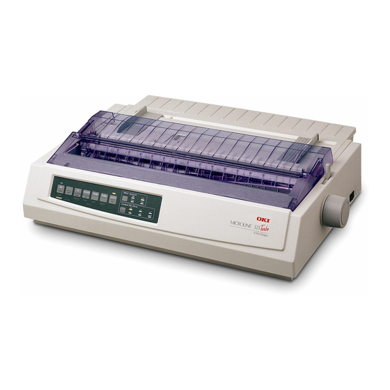
CONFIGURATION 1.1. Standard Printer Configuration This printer consists of the following assemblies: Sheet guide assy Platen knob Access cover assy Upper cover Traansformer assy Pull-up roller assy Control/Power supply assy Driver board Operation panel assy Main chassis assy Figure 1-1 Configuration 1 –... -
Page 7: Options
Options Cut sheet feeder unit (CSF) Single-bin CSF Attachment assy Pull-tractor assy 1 – 2... - Page 8 Bottom push tractor unit Roll paper stand (Narrow only) Serial I/F • RS-232C 1 – 3...
-
Page 9: Theory Of Operation
THEORY OF OPERATION Electrical Operation This section describes the electrical operation of the printer circuit. 2.1.1 Summary Fig. 2-1 shows the block diagram of the printer. The control board is made up of the microprocessors, peripheral circuits, drive circuits, sensors and interface connectors. - Page 10 Kbits 2 – 2...
- Page 11 Program ROM This is a 256 16 bits (4M bit) [MAX] EPROM with the control program for the printer stored. The MPU executes instructions under this program. The program ROM is assigned to the program memory area of the MPU and is fetched by the PSEN signal of the MPU.
- Page 12 RAM (MSM51C464A-80RS) The RAM is CMOS dynamic RAM with (64K 4-bit) 2 configuration, and used as buffers (such as receiving buffer, printing buffer, DLL buffer and working buffer). The following shows examples of the memory access operation. RAM 1 (Q3) A0~A7 RAM 2 (Q4) D0~D3...
- Page 13 EEPROM The EEPROM is a CMOS serial I/O type memory which is capable of electrically erasing and writing 1,024 bits. The EEPROM contains menu data. The following shows the memory access operation. EEPROM EEDIN-P EECS-P EEDOUT-P EECLK-P PRE = O PE = X EECS-P EECLK-P...
- Page 14 This LSI detects and controls the SP motor speeds by monitoring the two-phase sensor signals obtained from the DC motors and modifying the excitation phases as appropriate. This LSI is connected in multiplex to the MPU. A/D bus LSIC Clockout* A0~A19 LSICS D0~D15...
-
Page 15: Initialization
2.1.3 Initialization This printer is initialized when the power is turned on or when the I-PRIME-N signal is input from the host side via the parallel interface. For the initialize operation, the RST-N signal is first output from the reset circuit to reset the MPUs and LSIs. -
Page 16: Parallel Interface Control
2.1.4 Parallel Interface Control The parallel data input from the host to the interfaced LSI is latched to its internal register at the falling edge of the STROBE-N signal. At the same time, the LSI sets the BUSY signal to the high level to inform the host that the data is being processed, and outputs the RXD signal to inform the MPU of data reception. -
Page 17: Print Control
2.1.5 Print Control Print data is transmitted as parallel data (HEAD1~HEAD9) from the LSI to the print head. The LSI generates the print timing and drive time. Control/Power Supply Board Driver Board A/D bus DRIVER Print Head Print Data Print Data HEAD1-N~ HEAD1~ HEAD9-N... - Page 18 Print Compensation Control The print compensation methods are shown below: (a) Voltage compensation (See 2.1.8 “Alarm Circuit.”) (b) Temperature compensation (See 2.1.8 “Alarm Circuit.”) Pin stroke compensation Platen Print Head Pin 1, 2 As shown in the drawing left, the stroke length up to the platen is different for each pin.
- Page 19 (e) Print mode compensation According to the thickness of the printing medium, the print mode is compensated as shown in the table below: Head Gap Range Print speed 100% Drive time Short Long (Drive time lengthens at each step.) 2 – 11...
-
Page 20: Sp/Lf Motor Control
2.1.6 SP/LF Motor Control Space motor control The SP motor driver (HA13412) drives the three-phase brushless motor based on the phase signal (SPU, SPV and SPW) and the speed instruction data from the LSI. The MPU can identify the current speed of the space motor by measuring through the LSI the pulse length of the output (øA, øB) of the slit encoder included in the space motor. - Page 21 Encoder disk In the operation of the spacing motor, the PHASE-A and PHASE-B signals are generated when the encoder disk interrupts the photo sensor. The LSI divides these edge pulse signals in accordance with the print pitch, and sends the IPT signal to provide dot-on timing and carriage position detection timing. PHASE-A PHASE-B 1/720"...
- Page 22 LF motor control The LF motor driver (MTD2005F) drives the LF motor in two-phase or 1-2 phase bipolar, based on the phase changeover data and the output current data from the LSI. The data from the LSI is processed by a specific register contained in the LF motor driver to measure the overdrive time and to change the phase.
-
Page 23: Operation Panel
2.1.7 Operation Panel The clock synchronization OPCLK signal of the LSI is used to input the switch data and output the LED data through the operation panel control LSI (IC1: BU5148S). OPTXD OPTD OPCLK OPCK Command LED driver and Data OPCLR-N latch NPA2... - Page 24 2 – 16...
-
Page 25: Alarm Circuit
2.1.8 Alarm Circuit Head drive time alarm circuit This circuit monitors the drive time using the HDALM signal interlocked with the overdrive signal of each drive circuit. If the drive time of any drive circuit exceeds the specified time, the drive fault alarm circuit sends an ALARM-N signal to turn on the SCR (SO). - Page 26 Head overheat alarm The voltage of the output TSD signal of the thermistors, one of which is in the printhead and the other in the printhead driver, is monitored by the CPU/AD port to control the voltage Temp Stop 119°C Mode up °C ß°C...
-
Page 27: Power Supply Circuit
2.1.9 Power Supply Circuit This power supply circuit supplies the +5VDC, +8VDC, +40VDC, 10VAC. Control Board Noise Rectifier +40V filter Fuse circuit Trans- former Rectifier Regulation Circuit AC10V The uses of output voltages and signals are described below. Voltage/signal Logic IC/LED drive voltage Serial interface line voltage and SP motor driver + 40V Printhead, LF motor drive voltage, SP motor drive voltage... -
Page 28: Mechanical Operation
Mechanical Operation 2.2.1 Printhead Mechanism and Operation (See Figure 2-2.) The printhead is a spring charged 9-pin driving head using a permanent magnet. It is attached to the carriage, which moves parallel to the platen. Electrically, this unit is connected to the control circuits through the control board. - Page 29 Printhead Operation (See Figure 2-3.) (a) When the printhead is idle, the armature is attracted by a permanent magnet and the spring fixing the armature is compressed. The print wires fixed to each armature are thus concealed under the wire guide. (b) When a signal for a character to be printed is detected, a current flows through the coil.
- Page 30 Paper Print wire Printhead Platen When printing Paper Armature assembly Thermistor Print wire Wire guide Yoke Magnet assembly Spacer When not printing Paper Figure 2-3 2 – 22...
-
Page 31: Spacing Operation
2.2.2 Spacing Operation (See Figure 2-4.) The spacing mechanism consists of a carriage shaft mounted in parallel with the platen, and a carriage frame that moves along the shaft. It is driven by a DC motor mounted on the bottom of the carriage frame. - Page 32 Print Head Carriage shaft Space rack Carriage frame Encoder disk Encoder sensor Motor gear Adjusting screw Slider Adjusting gear Guide rail Figure 2-4 *Carriage Assy removed 2 – 24...
-
Page 33: Head Gap Adjusting
2.2.3 Head Gap Adjusting (See Figure 2-5.) The head gap adjusting lever moves back and forth to tilt the carriage frame, altering the gap between the printhead and the platen. The adjusting screw, which is connected to the adjusting gear rotates when the adjusting lever is moved creating a fine gap adjustment. - Page 34 Platen Range Carriage shaft Printhead Adjusting lever Adjusting screw Idler gear Adjusting gear Range from Narrows Printhead Adjusting screw Adjusting cam C.C.W. Platen Guide rail Widens Range from C.W. Figure 2-5 2 – 26...
-
Page 35: Ribbon Drive
2.2.4 Ribbon Drive (See Figure 2-6.) The ribbon driver mechanism moves the ribbon in synchronization with the space motor operation. The ribbon drive mechanism consist of the following items: (a) Ribbon drive gear assembly (b) Ribbon gear (space motor) Ribbon cartridge Ribbon cartridge An endless ribbon with a single direction feed is used. - Page 36 Ribbon cartridge Drive gear Ink reservoir Figure 2-6 2 – 28...
-
Page 37: Paper Feed Operation
2.2.5 Paper Feed Operation Paper is fed by turning the platen and the pin tractor, which is driven by the LF pulse motor. The paper feed mechanism consists of the following: Pulse motor with gears Decelerating gear Platen Tractor feed unit Pressure roller 2 –... - Page 38 Cut sheet and continuous sheet switching mechanism (See Figure 2-8.) Three different paper paths can be selected and set by the change lever. TOP (for cut sheets) When the cut sheet paper is used in the manual mode or fed by the CSF (option), set the change lever at the position marked TOP.
- Page 39 BOTTOM (Continuous sheet from bottom feeder) (option) When the change lever is set in the BOTTOM position, the rotation of the platen is transmitted to the drive gear of the bottom tractor feed unit through the idle gear to feed the sheet which set in the bottom tractor feed. At the same time, the switch lever turns on the bottom switch to inform the control board that you are in the continuous sheet mode.
- Page 40 Control Power supply Assy Bottom switch Switch lever Change gear shaft Rear switch Change lever Release shaft Change arm Platen BOTTOM Change lever REAR Tractor gear Change gear Platen gear (R) Reset spring Idle gear (Bottom tractor unit) Figure 2-8 2 –...
- Page 41 Cut-sheet feeder operation (See Figure 2-9.) The pulse motor used for the paper feed mechanism is mounted on the left of the frame, and the rotation of the motor is transmitted through decelerating gears (LF idle gear, platen gear) to the platen. When using cut-sheet paper, the change lever must be in the TOP position to grab the paper, while disengaging the push tractor.
- Page 42 Continuous paper feed operation (Rear) (See Figure 2-10.) The force transmitted to the platen turns the tractor gear by means of the platen gear, the idler gear, and the change gear. The rotation of the tractor gear turns the sheet feeder shaft, which moves the pin tractor belt, feeding the paper.
- Page 43 Pull tractor (option) and push tractor operation (See Figure 2-11) This mechanism supports the standard push tractor and an optional pull tractor. It can perform forward and reverse feed by sending paper either to the push tractor (for rear feed) or to the pull tractor (for bottom feed).
- Page 44 Pull tractor mechanism (option) (See Figure 2-12.) Bottom feed of continuous sheets is possible only when the optional pull tractor unit is installed. The rotation of the platen is transmitted to the idle gear of the pull tractor unit through the platen gear at the left end of the platen.
- Page 45 Bottom push feed operation (Option) (See Figure 2-13.) The bottom push feed of continuous sheet requires the bottom tractor feed unit When the platen turns, its rotational force is transmitted through the tractor idle gear and the tractor change gear to the tractor drive gear of the bottom push tractor, and paper is fed to the print start position.
- Page 46 Paper clamp mechanism (See Figure 2-14.) When setting the change lever to the BOTTOM , TOP or REAR position, the operation of the front release gear arm changes according to the position of the release cam. At the same time, the position of the cam relative to the front release gear arm changes, opening or closing the pressure roller.
- Page 47 Change lever Release cam Platen Front release gear arm BOTTOM Pressure rollers REAR Figure 2-14 2 – 39...
-
Page 48: Paper Detection Mechanism
2.2.6 Paper Detection Mechanism (See Figure 2-15.) Cut sheet detection When the sheet is inserted, point A is pushed backward and the paper near end lever B rotates counterclockwise (CCW). At this time, the rear sensor lever rotates counterclockwise (CCW) and pulls out of the rear and top paper end sensor to detect that the sheet is inserted. - Page 49 Paper end sensor Sensor lever Shaded portion Paper end lever Bottom paper end lever Figure 2-15 2 – 41...
- Page 50 Top line print mechanism (See Figure 2-16.) The top edge of the sheet is protected by the ribbon protector so that it can stop at a position very close to the printhead (0 tear-off position) to start printing at the top of the sheet without causing it to crumple or curl up.
- Page 51 Platen Ribbon protector Printhead Carriage frame assembly Figure 2-16 2 – 43...
-
Page 52: Automatic Sheet Feed
2.2.7 Automatic Sheet Feed This function is used to feed in the sheet automatically up to the print start position when the cut sheet or the continuous sheet paper is used. Operational procedure When using cut sheet paper: Set the change lever to the TOP position. (See Figure 2-17.) Insert a sheet of paper between the platen and the paper chute. - Page 53 When using continouos sheet paper Set the change lever either to the rear or the bottom position. (See Figure 2-17.) Load paper either on the push tractor or on the bottom tractor. Press the “FF/LOAD” button. The LF motor starts to feed the paper up to the print start position. The paper feeds up to the TOF position (Factory default: 0.35 inches from the top).
-
Page 54: Paper Park Function
2.2.8 Paper Park Function (Continuous sheet paper) Continuous sheet paper can be backed out automatically by using the “PARK” button on the operation panel. Press the “PARK” button. Reverse LFstarts and paper feeds in reverse until paper end occurs or a maximum of 19 inches have been fed. -
Page 55: Assembly/Disassembly
ASSEMBLY/DISASSEMBLY This section explains the procedures for removing and installing various assemblies and units in the field. Description is mainly limited to the removal procedure; installation should basically be performed in the reverse sequence of the removal procedure. Precautions for Parts Replacement Remove the AC power cord and the interface cable before disassembling or assembling. -
Page 56: Service Tools
Service Tools Table 3.1 lists the tools necessary for replacing printed circuit boards and parts of units in the field. Table 3.1 Service tools Service Tool Q’ty Remarks No. 1-100 Phillips Screws screwdriver 2.6 mm No. 2-200 Phillips Screws screwdriver 3-5 mm No. -
Page 57: Disassembly/Reassembly Procedure
Disassembly/Reassembly Procedure This section explains the assembly replacement procedures according to the following disassembly system. Parts Layout Upper cover assy Transformer assy Printhead Control/Power supply board Driver board Operation panel board Printer unit Figure 3-1 Printer unit 3 – 3... -
Page 58: Ribbon Protector
How to Change Parts This section explains how to change parts and assemblies appearing in the disassembly diagram below. 3.3.1 Printhead Printer unit 3.3.2 Ribbon protector 3.3.3 Pull-up roller assy 3.3.4 Upper cover, access cover and sheet guide 3.3.5 Gear case assy 3.3.6 PC connector 3.3.7... - Page 59 3.3.1 Printhead Open the access cover. Pull up and rotate the head clamp to unclamp the printhead as shown in fig. 3.3.1. Disconnect the printhead from PC connector and remove. To install, reverse the removal steps. Notes on installation: Insert the printhead into the PC connector while pushing it against the carriage frame The head clamp...
- Page 60 3.3.2 Ribbon Protector Remove the printhead (see 3.3.1). Open the pull-up roller cover Remove the shim on the carriage frame. Loosen the screws holding the carriage assembly to the carriage frame--this allows more play between the printhead and the platen. Raise and remove the ribbon protector To install, follow the removal steps in reverse order.
-
Page 61: Pull-Up Roller Assy
3.3.3 Pull-up Roller Assy Open the access cover Lift up the sheet guide Assy to remove. Tilting the pull-up roller Assy toward the front, remove it from the shaft of platen Assy To install, follow the removal steps in reverse order. Note: Remove the sheet guide Assy before installing or removing the pull-up roller Assy 3 –... -
Page 62: Upper Cover Assy, Access Cover Assy And Sheet Guide Assy
3.3.4 Upper Cover Assy, Access Cover Assy and Sheet Guide Assy Pull off the platen knob Open the access cover Assy toward the front to remove. Lift up the sheet guide Assy to remove. Turn the change lever toward the bottom position. Insert a flat-blade screwdriver into grooves of frame (5 places for ML 321, 4 places for ML320) and twist to disengage claws of upper cover Raise the front side of upper cover Assy... -
Page 63: Gear Case Assy
3.3.5 Gear Case Assy Remove the printhead (see 3.31). Remove the shim from the cariage frame. Remove the upper cover (see 3.3.4). Move the carriage Assy to right side, remove two screws , then remove the carriage Assy. Disengage claws on the gear Assy (4 places). Using a flat-blade screwdriver, push to widen the claw for easy disengagement. -
Page 64: Pc Connector
3.3.6 PC Connector Remove the upper cover (see 3.3.4). Remove the printhead (see 3.3.1). Remove the shim from the carriage frame. Remove the gear case Assy (see 3.3.5). Remove the PC connector from the space motor Assy To install, follow the removal steps in reverse order. Be sure to replace the shim on the carraige frame in exactly the same position as it was before disassembly Notes on installation: Do not touch the space motor... -
Page 65: Space Motor, Guide Roller Assy
3.3.7 Space Motor, Guide Roller Assy Remove the printhead (see 3.3.1). Remove the upper cover (see 3.3.4). Remove the gear case Assy (see 3.3.5). Remove the PC connector (see 3.3.6). Remove screw , then the guide roller Assy from the space motor Assy Push down on the carriage cable and remove it. -
Page 66: Space Rack
3.3.8 Space Rack Remove the upper cover (see 3.3.4). Remove the printhead (see 3.3.1). Remove the shim from the carriage frame. Remove the gear case Assy (see 3.3.5). Remove the space motor Assy (see 3.3.7). Remove the spring Disengage the claw on left side of space rack from the frame, and remove the space rack in upper direction. -
Page 67: Carriage Cable
3.3.9 Carriage Cable Remove the upper cover (see 3.3.4). Remove the printhead (see 3.3.1). Remove the shim from the carriage frame. Remove the gear case Assy (see 3.3.5). Remove the space motor Assy (see 3.3.7). Remove the two screws , release the driver board and PCB board by lifting clamp , and disconnect cable from connector... -
Page 68: Backup Roller Holder Assy
3.3.10 Backup Roller Holder Assy Remove the upper cover (see 3.3.4). Remove the printhead (see 3.3.1). Remove the carriage Assy (see 3.3.5 (3)). Remove the backup roller spring Disengage claws of roller holder from the carriage frame (2 places), and remove the backup roller holder assy To install, follow the removal steps in reverse order. -
Page 69: Platen Assy
3.3.11 Platen Assy Remove the printhead (see 3.3.1). Remove the upper cover (see 3.3.1). Remove the pull-up roller Assy (see 3.3.3). Remove the ribbon protector (see 3.3.2). Turn the change lever to the bottom position. Push in the lock levers on both sides to unlock the Assy from the frame, then rotate them upward 90 . -
Page 70: Driver Board (Sddv)
3.3.12 Driver Board (SDDV) Remove the upper cover (see 3.3.4). Remove the two screws , and release the driver board by lifting clamp Disconnect all cables from driver board To install, follow the removal steps in reverse order. Note on installation : Insert sensor lever in the sensor as shown when installing the driver board Sensor... -
Page 71: Lf Motor
3.3.13 LF Motor Remove the upper cover (see 3.3.4). Remove the printhead (see 3.3.1). Remove the ribbon protector (see 3.3.2). Remove the pull-up roller Assy (see 3.3.3). Remove the platen Assy (see 3.3.11). Remove the driver board (see 3.3.12). Remove the left FG plate lift base at three points to release tabs. -
Page 72: Operation Panel Pcb (Leop)
3.3.14 Operation Panel PCB (LEOP) Remove the upper cover (see 3.3.4). Disconnect cable from connector of driver board Disengage claws on both sides from the frame, and remove the operation panel Open claws (8 places) and remove the operation panel PCB from the operation panel To install, follow the removal steps in reverse order. -
Page 73: Control/Power Supply Board (Sdct)
3.3.15 Control/Power Supply Board (SDCT) Remove the upper cover (see 3.3.4). Disconnect the two flexible cables from connector on the Control/Power Supply Board Remove cable from connector on the control/power supply board Remove the two screws , and remove the controlpower supply board To install, follow the removal steps in reverse order. -
Page 74: Transformer Assy
3.3.16 Transformer Assy Remove the upper cover (see 3.3.4). Remove AC inlet and AC switch from the frame guide. Disconnect the cable from the connector on the Control/Power Supply Board Remove a screw and disconnect ground cable Remove two screws and shift the transformer Assy to the left and remove it. -
Page 75: Change Lever And Gears
3.3.17 Change Lever and Gears Remove the upper cover (see 3.3.4). Release the reset spring from the tab, remove it, then remove the idle gear , the tractor gear and the change gear Push back the protrusion of the change gear shaft gently with a flatblade screw driver . -
Page 76: Carriage Shaft
3.3.18 Carriage Shaft Remove the printhead (see 3.3.1). Remove the upper cover (see 3.3.4). Remove the driver board (see 3.3.12). Remove the FG plate (L) Slide the carriage shaft to the left side (in the direction of the arrow) to remove. To install, reverse the removal procedure. -
Page 77: Paper Pan
3.3.19 Paper Pan Remove the printhead (see 3.3.1). Remove the ribbon protector (see 3.3.2). Remove the pull-up roller assy (see 3.3.2). Remove the upper cover assy (see 3.3.4). Remove the platen assy (see 3.3.11). Release claws Lift up the paper chute assy and remove. -
Page 78: Rear Tractor Assy
3.3.20 Rear Tractor Assy Remove the printhead (see 3.3.1). Remove the ribbon protector (see 3.3.2). Remove the pull-up roller assy (see 3.3.3) Remove the upper cover (see 3.3.4). Remove the reset spring (see 3.3.17 (3)) Remove the tractor gear Shift the drive shaft to the right side to remove (in the direction of the arrow). -
Page 79: Rear Pressure Assy
3.3.21 Rear Pressure Assy Remove the upper cover (see 3.3.4). Remove the change lever and gears (see 3.3.17). Remove the paper pan (see 3.3.19). Remove the rear pressure roller Rotate the release shaft and move it to the left to detach the release shaft Match the main frame rib A with the protrusion B of the release shaft. -
Page 80: Switch Lever
3.3.22 Switch Lever Remove the upper cover (see 3.3.4). Remove the change lever and gears (see 3.3.17). Remove the paper pan (see 3.3.19). Remove the rear pressure assy (see 3.3.21). Pull the switch lever toward you and remove it upward. To install, follow the removal steps in reverse order. -
Page 81: Adjustment
ADJUSTMENT Be sure to carry out these adjustments with the printer mechanism installed on the lower cover. Be sure to carry out these adjustment operations on a level and highly rigid work table (flatness: less than 0.039 inch or 1 mm) so as to minimize adjustment error. 4 –... - Page 82 Item Specification Drawing Adjustment method 4–1–1 Gap between the plat- It shall be measured en and the printhead at 3 points: the left end, the center and 1) Parallelism the right end of the justment Variation of platen. value at the left, the center Adjustment method and the right...
- Page 83 Item Specification Drawing Adjustment method Note 1) The head gap shall be measured with the Adjust lever change lever set to rear position. Note 2) The head gap shall be Adjust gear measured positioning the platen gear (R) craw on the top. Adjust Note 3) spring...
- Page 84 Item Specification Drawing Adjustment method Gap between the con- 0.3mm or more Verify the following. tact and the monitor Make sure that the Adjust lever gap between the con- tact and the motor PCB is 0.3 mm or more. 0.3mm or more Contact Motor PCB...
- Page 85 Item Specification Drawing Adjustment method 4–2 between 1 0.5 Verify the following. platen and the paper (1) When the change lever is set at Friction position, the gap between Change lever the platen and the paper pan at the Bottom Rear rear side shall be 1 0.5mm.
- Page 86 Item Specification Drawing Adjustment method 4–4–1 Rotation of the push Verify: tractor The tractor gear shall rotate smoothly when the change lever is set at Friction posi- tion. Change lever (Center friction) Push tractor Tractor gear Slight backlash 4–4–2 Backlash between Approx.
- Page 87 Item Specification Drawing Adjustment method 4–5–1 Ribbon feed Verify: Ribbon shall be fed smoothly when the carriage is moved from side to side. Ribbon feeding 4–5–2 Running load to spac- 250g or less Verify: Ribbon ing mechanism without a rib- Make sure that the bon cartridge power is turned off at...
- Page 88 Item Specification Drawing Adjustment method 4–6 Engagement of the Verify: double gear and the LF The idle gear of the motor idle gear of the LF motor and the LF Motor Platen gear (L) Platen Assy. platen gear (L) and idle gear the bias gear of the platen shall be in...
-
Page 89: Cleaning And Lubrication
CLEANING AND LUBRICATION Cleaning Cautions Be sure to turn OFF the AC POWER switch before cleaning. Remove the AC power cord from the printer. Avoid dust inside the printer mechanism when cleaning. If a lubricated part has been cleaned, be sure to apply lubricating oil to that part after cleaning. - Page 90 Carriage shaft 5 – 2...
-
Page 91: Lubrication
Lubrication This printer is designed to be maintenance free and requires no lubrication during normal operation. However it is necessary to apply lubricant if the printer is disassembled, reassembled, cleaned, or if parts have been changed. Cleaning time Remarks: 1) Turn off the power before cleaning. 2) Make sure that paper dust does not fall inside of the machine. - Page 92 Lubrication point Ribbon feed gear Assy. Drive gear shaft (upper and lower) Planetary gear shaft PM-B (0.006 0.002g) (upper and lower) EM-30L-A Idle gear shaft (upper and lower) PM-B (0.006 0.002g) Space rack Space rack Rack upper side Approx. 35 (greasing range) EM-30L-A 5 –...
- Page 93 Platen Assy. Contact face of the platen shaft Bias gear and platen FG spring EM-30-L-B Grease the contact face of platen gear (L) and bias gear PM-B Platen gear (L) 5 – 5...
- Page 94 Tractor driving mechanism Change lever Sliding surface of change arm and Tractor gear bearing portion change lever EM-30L-A EM-30L-A Change arm Idle gear teeth EM-30L-A Reset spring Gear bearing portion Sliding surface of change EM-30L-A Sliding surface of lever and gear reset spring and gear EM-30L-A EM-30L-A...
- Page 95 Pressure roller Change arm Sliding part of release shaft and change arm EM-30L-A Release shaft Support spring Contact part of the Front pressure roller support spring and shaft EM-30L-A Contact part of the rear holder and shaft EM-30L-A Controller holder Sliding part of the rear roller holder Sliding part of the and release shaft cam surface...
- Page 96 Pull up roller Assy. Pull-up roller frame Pull-up roller shaft All bearing parts of the pull-up roller shaft and pull-up roller frame EM-30L-B Gear and post EM-30L-A 5 – 8...
- Page 97 Main chassis Assy. Grease part (N: 3 parts, W: 5 parts) rear side EM-30L-A Models ML320 Turbo ML321 Turbo Grease part at rib (N: 9 portions W: 13 portions) EM-30L-A Grease part 5 – 9...
- Page 98 Carriage Assy. NK2-10-SUS Bearing part of the guide roller EM-30L-B 5 – 10...
-
Page 99: Troubleshooting And Repair
TROUBLESHOOTING AND REPAIR Items to Check Before Repair Check the inspection items specified in the instruction manual. Find out as many details of the problem as possible from the customer. IN the shop, inspect under conditions as close as possible to those at the time the trouble occurred. -
Page 100: Lamp Display
Lamp Display Printer mode display Table 6.2 LED CONDITION ALARM TROUBLE ALARM CONTENTS EXPLANATION CATEGORY SHOOTING ALARM MENU 10CPI 15CPI From, cut sheet or bottom Paper end alarm — — — Set New paper. paper end Change lever is set to TOP •... - Page 101 6 – 3...
- Page 102 6 – 4...
- Page 103 6 – 5...
-
Page 104: Connection Circuit Check For Printhead And Sp/Lf Motor
Connection Circuit Check for Printhead and SP/LF Motor Printhead Signal Connector pin number HEAD1 HEAD2 HEAD4 HEAD6 HEAD8 Thermistor HTEMP +40V +40V +40V HEAD9 HEAD7 HEAD5 HEAD3 6 – 6... - Page 105 Line Feed Motor Resistance of each coil should be about 7.6 . Signal Connector pin number motor 6 – 7...
- Page 106 Space Motor Resistance of each coil should be about 5 . Signal Connector pin number SP-U SP-V Motor SP-W øA øB 6 – 8...
-
Page 107: Troubleshooting Flow Chart
Troubleshooting Flow Chart Power is not supplied. Is the AC cable connected correctly? Connect the AC cable correctly. Is fuse F1 on the transformer assy/or F1 on the control/power supply board blown? Replace fuse (with same type and rating). Remedied? Does DC + 8V out? Turn power off, remove printhead, then turn on. - Page 108 No Yes Replace driver board. Driver Board Replace transformer assy. Remedied? No Yes 20••••••••••••1 Replace control/power supply board. Pin No. 19 18 17 16 15 14 13 10 Signal +40V (F.G) (0V) 6 – 10...
-
Page 109: No Spacing Operation
No spacing operation (The alarm LED Blinks) Is carriage assembly binding or jammed? Check for dust build-up around space motor, between the teeth of the space rack, back up roller, ribbon feed mechanism, and carriage frame etc. Replace space motor assy. Remedied? Replace driver board. -
Page 110: Homing Does Not End Normally
Homing does not end normally Check for dust or paper build-up around space motor. (Space rack, ribbon feed assembly back up roller, carriage frame, support protector and ribbon protector.) Remedied? Replace space motor assy. Replace space motor assy. Remedied? Replace carriage cable. Remedied? Replace driver board. -
Page 111: Paper Jam While Paper Insertion
Paper jam while paper insertion Jam 1 Check the ribbon protector. Make sure the pull up roller cover is closed properly. Pull up roller cover Platen Paper Ribon Protector Jam 2 (wrinkled paper) Check around pressure roller mechanism for the following: •... -
Page 112: Smearing/Missing Dots
Smearing/missing dots Does ALARM LED blink and display alarm? See Tables 6.2 and 6.3 for troubleshooting information. Replace printhead. Remedied? Replace driver board. Remedied? Replace carriage cable or space motor assy. 6 – 14... -
Page 113: Faint Or Dark Print
Faint or dark print Is the printhead gap set properly? Adjust the printhead gap (see section 5). Remedied? Replace printhead. Remedied? Replace driver board. Remedied? Replace ribbon feed mechanism. 6 – 15... -
Page 114: Ribbon Feed Trouble
Ribbon feed trouble Remove the ribbon cartridge. Move carriage to left and right. Does the ribbon drive shaft rotate? Change ribbon cartridge. Remove ribbon feed mechanism. Move carriage to left and right. Does the ribbon drive shaft rotate? Replace Ribbon feed mechanism. Replace space motor assy. -
Page 115: Line Feed Trouble
Line feed trouble Turn the power off, and rotate the platen manually. Does the platen rotate smoothly? Is the platen gear (L) broken? Replace platen assembly. Is the LF motor idle gear broken? Replace the LF motor assembly or LF idle gear. Is the platen gear (R), idle gear or change gear broken? Replace the gear. -
Page 116: Malfunction Of Switch On Operation Panel
Malfunction of switch on operation panel Is the CN1 of Operation panel connected to the CN3 on the driver board? Connect the cable properly. Replace operation panel board. Remedied? Replace driver board. 6 – 18... -
Page 117: Data Receiving Failure
Data receiving failure Is the SEL LED blinking? Printer went into the print suppress mode. Wait until printer receives DC1 code, or change the menu item “Print suppress” to “Ineffective” when the function is not required. Is the I/F RS232C? Go to step 10-2 Does the SEL LED light up? - Page 118 10-2 (RS232C I/F) Printer I/F pin assignment. Is the correct cable used? 2 pin, 3 pin, 11 pin, 20 pin, Change I/F cable. 6 pin. Is the ALARM LED blinking? See tables 6.2 and 6.3 for troubleshooting. Make sure the parameters for RS232C in the menu are correct. Baud rate Bit length Parity...
- Page 119 Replace RS232C board. Remedied? Replace driver board. 6 – 21...
-
Page 120: Pcb Layout
PCB LAYOUT PCB list Circuit board SDCT (Control/Power Supply) Circuit board SDDV (Driver) Circuit board LEOP-3 (Operation Panel) A – 1... -
Page 121: Spare Parts List
SPARE PARTS LIST B – 1... - Page 122 Figure 11-1 Upper Cover Assy B – 2...
- Page 123 Figure 11-1 Upper Cover Assy Q'ty Part No. Description Q'ty Required Remarks ODA P/N 1PP4128-1186P6 Upper cover (N) For ML320 Turbo For INT 1PP4128-1186P4 Upper cover (N) For ML320 Turbo For OEL 1PP4128-1186P2 Upper cover (N) For ML320 Turbo 53076502 1PP4128-1231P6 Upper cover (W) For ML321 Turbo For INT...
- Page 124 Figure 11-2 Printer General Assy B – 4...
- Page 125 Figure 11-2 Printer General Assy Q'ty Part No. Description Q'ty Remarks Required ODA P/N 2PP4025-2871P20 Platen Knob 51902220 4YA4042-1543G301 Control/power supply For ODA/no ROM 55080801 board (SDCT) 4YA4042-1543G302 Control/power supply For OEL board (SDCT) 4YA4042-1543G303 Control/power supply For INT board (SDCT) 4YA4042-1549G1 Driver board (SDDV) 55080701...
- Page 126 Figure 11-3 Printer Unit B – 6...
- Page 127 Figure 11-3 Printer Unit Q'ty Part No. Description Q'ty Remarks ODA P/N Required 3PA4044-5002G2 Main chassis assy (N) For ML320 Turbo 53348801 3PA4044-5152G2 Main chassis assy (W) For ML321 Turbo 53348901 3PP4044-5012P1 Bottom paper end lever 50809201 4PP4044-5019P1 Pressure spring (F) For ML320 Turbo 50931301 4PP4044-5019P2 Pressure spring (F)
- Page 128 Q'ty Part No. Description Q'ty Remarks ODA P/N Required 3PA4044-5025G2 Platen assy (N) For ML320 Turbo 50114801 3PA4044-5159G2 Platen assy (W) For ML321 Turbo 50114901 3PP4044-5010P1 Space rack gear (N) For ML320 Turbo 53349601 3PP4044-5156P1 Space rack gear (W) For ML321 Turbo 53349701 4PB4025-3377P2 Tension spring for space 50923502...
- Page 129 Figure 11-4 Carriage Assy B – 9...
- Page 130 Figure 11-4 Carriage Option Assy Q'ty Part No. Description Q'ty Remarks ODA# Required 4PP4044-5061G1 Carriage frame set 53349801 4PA4025-3718G1 Back up roller holder assy 53343201 4PP4025-3398P1 Guide roller 53341901 3PP4044-5065P1 Guide roller holder 53350101 4YA4044-5100G1 Space motor assy 56513701 3PB4044-5506P1 Head cable (9N) For ML320 Turbo 56633801 3PB4044-5507P1...
- Page 131 [Pull-Tractor] [Bottom-Tractor] [I/F Board] Figure 11-5 Option Spare Parts B – 11...
- Page 132 Figure 11-5 Option Spare Parts Q'ty Part No. Description Q'ty Remarks ODA P/N Required 4PA4025-3608G1 Pull and bottom 50098001 tractor assy (L) 4PA4025-3603G1 Pull and bottom 50097901 tractor assy (R) 2PP4128-1239G1 Tractor cover assy (N) For ML320 Turbo 53077201 2PP4128-1243G1 Tractor cover assy (W) For ML321 Turbo 53077301 1PA4128-1277G1...
-
Page 133: Rs-232C Serial Interface Board (Option
APPENDIX C RS-232C SERIAL INTERFACE BOARD GENERAL This section describes the operation of the RS-232C Serial Interface board installed in the Printer as an option using a start-stop synchronization and serial communications circuit. This serial interface board is capable of transmitting and receiving simultaneously at speeds up to 19,200 bits per second. -
Page 134: Operation Description
OPERATION DESCRIPTION Element Description 80C51 with MASK ROM An eight-bit microprocessor controller that controls the following: (a.) Serial interface protocol and data transfer through a serial port. (b.) Message buffer. (c.) Transmission of parallel data to the printer. SN75189 An RS-232C standard line receiver SN75188 An RS-232C standard line driver. - Page 135 80C51 ADR latch IF WR 2764 DB0 to DB9 LS245 8 KB 8 KB Serial data control line +5 VD +9 V ±9 V power 10 VAC Bus line supply circuit –9 V +5 V Control line Figure C-2-1 Block Diagram C –...
- Page 136 2.2.1 Operation at power on After power is turned on, an RST OUT signal is sent from the printer control board to reset the printer. When the reset is canceled, the 80C51 CPU performs initialization. Initialization consists of setting the 80C51 timer and setting the serial mode. 2.2.2.
-
Page 137: Communication Procedure Flowchart
Communication Procedure Flowchart 2.3.1 Mode a Ready/Busy Received one character? Is DSR valid? DSR High? Buffer overflow? Parity error Error? No error Store the received Store 40 H in buffer. character in buffer. Is the printer in DESELECT state or is the paper low? Is remaining buffer space <... - Page 138 2.3.2 Mode b X-ON, X-OFF Received one character? Is DSR valid? DSR High? Buffer overflow? Parity error Error? No error Store the received Store 40 H in buffer. character in buffer. Is the printer in DESELECT state or is the paper low? Is remaining buffer space <...
-
Page 139: Troubleshooting Flowchart
TROUBLESHOOTING FLOWCHART Before Repairing a Fault Before servicing the printer, ask the customer under what circumstances the trouble occurred and record the response. Before you start troubleshooting, operate the printer under the same conditions as that at the time of the problem to see if the same trouble occurs again. If not, perform the printer's self test and thoroughly test the printer's functionality. - Page 140 The data is not received using a serial interface. (A protocol is set to READY/BUSY state, and BUSY LINE is in SSD + state.) Is the OSC oscillation waveform as specified in Figure C-3-1? 90ns + 4 to + 5V 0 to + 1V T (ns) Figure C-3-1...
- Page 141 Yes Are ALE, PSEN, RD, WR, signals as specified in Figure C-3-3? 542ns 180ns PSEN 271ns 542ns RD/WR Figure C-3-3 Replace the Q3. Yes Are (T1) SELECT and (INTO) BUSY signals low level? Check Q501 on the SDDV board. Yes Are +9V and -9V input to Q1? Replace defective component in +9/–9 volt control circuit.
- Page 142 In receiving by serial interface, printing data is omitted or printing operation is not performed. Are RxD and SSD of Q3 as specified in Figure C-3-4? Replace the Q2. Yes Are, WR, and BUS signals of Q3 pin 3 as specified in Figure C-3-5? 542ns Q3-3 Figure C-3-5...
- Page 143 Local Test 3.3.1 Circuit test mode 3.3.1.1Setting Diagnostic test (set by menu) Test connector Connect the test connector shown in Figure C-3-6 to the interface connector CN1 on the LXH1 board Equivalent to Cannon DB-25P Figure C-3-6 Test Connector Connection Diagram 3.3.1.2Function After the settings outlined in Section 3.3.1.1 are completed and power is turned on, the serial interface checks the message buffer memory and interface driver/receiver circuit.
- Page 144 The program revision using two numerical characters is printed. “LOOP TEST” is printed. Memory is checked for the message buffer. Prints “OK” is printed if the memory check is OK and “BAD” is printed if the memory check fails. Output level to DTR, RTS, and SSD signals is dropped low. If DSR, CTS, or CD signals is High, “IF BAD”...
- Page 145 Microline 320/321-Turbo Service Manual Part Number 59273701 Printed in the USA...
Need help?
Do you have a question about the MICROLINE 320 and is the answer not in the manual?
Questions and answers