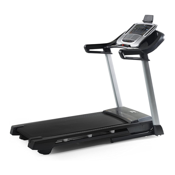
NordicTrack C 700 User Manual
Treadmill
Hide thumbs
Also See for C 700:
- Quick assembly manual (4 pages) ,
- User manual (40 pages) ,
- User manual (36 pages)
Table of Contents
Advertisement
www.nordictrack.com
Model No. 831.24988.2
Serial No.
Write the serial number in the space
above for reference.
Serial Number
Decal
ACTIVATE YOUR
WARRANTY
To register your product and
activate your warranty today, go
to www.nordictrackservice.com/
registration.
CUSTOMER CARE
For service at any time, go to
www.nordictrackservice.com.
Or call 1-800-TO-BE-FIT
(1-800-862-3348)
Mon.–Fri. 6 a.m.–6 p.m. MT
Sat. 8 a.m.–12 p.m. MT
Please do not contact the store.
CAUTION
Read all precautions and instruc-
tions in this manual before using
this equipment. Save this manual
for future reference.
USER'S MANUAL
Advertisement
Table of Contents

Related Manuals for NordicTrack C 700


Summary of Contents for NordicTrack C 700
- Page 1 Model No. 831.24988.2 USER’S MANUAL Serial No. Write the serial number in the space above for reference. Serial Number Decal ACTIVATE YOUR WARRANTY To register your product and activate your warranty today, go to www.nordictrackservice.com/ registration. CUSTOMER CARE For service at any time, go to www.nordictrackservice.com.
-
Page 2: Table Of Contents
Apply the decal in the location shown. Note: The decals may not be shown at actual size. 305284 NORDICTRACK is a registered trademark of ICON IP, Inc. -
Page 3: Important Precautions
20. To purchase a surge suppressor, see your local 4. The treadmill is intended for home use only. NORDICTRACK dealer, call the telephone Do not use the treadmill in any commercial, number on the front cover of this manual, or rental, or institutional setting. - Page 4 20. The heart rate monitor is not a medical 24. Never insert any object into any opening on device. Various factors, including the user’s the treadmill. movement, may affect the accuracy of heart rate readings. The heart rate monitor is 25.
- Page 6 STANDARD SERVICE PLANS...
-
Page 7: Before You Begin
Thank you for selecting the revolutionary reading this manual, please see the front cover of this NORDICTRACK C 700 treadmill. The C 700 treadmill manual. To help us assist you, please note the product ® offers an impressive selection of features designed model number and serial number before contacting us. -
Page 8: Part Identification Chart
PART IDENTIFICATION CHART Use the drawings below to identify small parts used for assembly. The number in parentheses below each draw- ing is the key number of the part, from the PART LIST near the end of this manual. The number following the key number is the quantity used for assembly. -
Page 9: Assembly
ASSEMBLY • Assembly requires two persons. • To identify small parts, see page 8. • Place all parts in a cleared area and remove the • Assembly requires the following tools: packing materials. Do not dispose of the packing the included hex key materials until you finish all assembly steps. - Page 10 2. Make sure that the power cord is unplugged. Wire Press a Base Cap (74) into each side of the Base (94). Identify the Right Upright (90). Have a second person hold the Right Upright near the Base (94). See the inset drawing. Tie the wire tie in the Right Upright (90) securely around the end of the Upright Wire (81).
- Page 11 4. Insert a Wheel Spacer (63) into a Front Wheel (62). Hold the Front Wheel inside the bottom of the Right Upright (90), and insert a 3/8" x 4" Screw (7) with a 3/8" Star Washer (13) into the Right Upright and the Front Wheel. Repeat this step with the Left Upright (not shown).
-
Page 12: Remove And Discard The Two Indicated Screws
6. Remove the four indicated 5/16" x 3/4" Screws (4) from the Uprights (89, 90) (only one side is shown). The Screws will be used in a later step. Identify the Left and Right Base Covers (82, 83). Slide the Left Base Cover onto the Left Upright (89), and slide the Right Base Cover onto the Right Upright (90). -
Page 13: E). Then, Remove The Pulse Crossbar (93
8. Attach the left handrail assembly (D) to the Left Upright (89) with two 5/16" x 2 1/2" Screws (28) and two 5/16" Star Washers (11). Do not fully tighten the Screws yet. Remove and discard the two indicated screws (C). - Page 14 10. Identify the Right and Left Trays (27, 36). Attach the Trays (27, 36) to the Console Base (64) with eight #8 x 1/2" Screws (1). Tip: It may be easier to start the two inside Screws and then slide the Trays into place before tighten- ing the other six Screws.
- Page 15 12. With the help of a second person, hold the con- Console sole assembly near the Handrails (86) (only one Assembly side is shown). Connect the ground wire from the console assembly to the Console Ground Wire (58) on the Pulse Crossbar (93). Console Wire Connect the Upright Wire (81) to the console...
- Page 16 14. Attach the Pulse Crossbar (93) to the console assembly with six #8 x 3/4" Screws (2). Start all Console six Screws, and then tighten them. Assembly Firmly tighten the four 5/16" x 3/4" Screws (4). 15. Check the gaps between the handrail assem- blies (B, D) and the console assembly.
- Page 17 16. Tighten a #8 x 1" Screw (103) with a Handrail Plate (105) and a #10 Washer (104) into the Left Outside Upright Cover (87) and into the bottom of the left handrail assembly (D). Make sure to orient the Handrail Plate as shown. Do not overtighten the Screw.
- Page 18 18. Firmly tighten the six 3/8" x 4" Screws (7) (only one side is shown). Press the Left Base Cover (82) and the Right Base Cover (83) onto the Base (94). 19. Note: If assembled on a smooth surface, the treadmill may roll forward during this step.
- Page 19 20. Orient the Storage Latch (53) so that the decals are facing away from the treadmill as shown. Attach the lower end of the Storage Latch (53) to the bracket on the Base (94) with a 5/16" x 1 3/4" Bolt (6) and a 5/16"...
-
Page 20: Operation And Adjustment
OPERATION AND ADJUSTMENT HOW TO CONNECT THE POWER CORD nominal 120-volt circuit capable of carrying 15 or more amps. To avoid overloading the circuit, do Use a Surge Suppressor not plug other electrical devices, except for low- power devices such as cell phone chargers, into Your treadmill, like other electronic equipment, can be the surge suppressor or into an outlet on the same circuit. - Page 21 CONSOLE DIAGRAM FEATURES OF THE CONSOLE You can even listen to your favorite workout music or audio books with the console’s sound system while you The treadmill console offers an impressive array of exercise. features designed to make your workouts more effec- To turn on the power, see page 22.
- Page 22 HOW TO TURN ON THE POWER HOW TO USE THE MANUAL MODE IMPORTANT: If the treadmill has been exposed to 1. Insert the key into the console. cold temperatures, allow it to warm to room tem- perature before you turn on the power. If you do See HOW TO TURN ON THE POWER at the left.
- Page 23 4. Change the incline of the treadmill as desired. The My Trail tab will show a track that represents 1/4 mile (400 m). As you exercise, the flashing To change the incline of the treadmill, press the rectangle will show your progress. The My Trail tab Incline increase and decrease buttons or one of the will also show the number of laps you complete.
- Page 24 6. Measure your heart rate if desired. Press the fan buttons repeatedly to select a Before using fan speed or the auto the handgrip mode, or to turn off the heart rate moni- fan. tor, remove the sheets of plastic 8.
- Page 25 HOW TO USE AN ONBOARD WORKOUT The workout will continue in this way until the last segment of the profile flashes in the display and the 1. Insert the key into the console. last segment ends. The walking belt will then slow to a stop.
- Page 26 HOW TO USE A SET-A-GOAL WORKOUT HOW TO USE AN IFIT WORKOUT 1. Insert the key into the console. Note: To use an iFit workout, you must have an optional iFit module. To purchase an iFit module at any time, go to www.iFit.com or call the telephone See HOW TO TURN ON THE POWER on page 22.
- Page 27 For more information about the iFit workouts, 7. Measure your heart rate if desired. please see www.iFit.com. See step 6 on page 24. When you select an iFit workout, the display will 8. Turn on the fan if desired. show the name, duration, maximum speed setting, and distance of the workout.
- Page 28 THE SETTINGS MODE If an iFit module is connected, you may also The console features a settings mode that keeps track select the following screens: of treadmill information and allows you to personalize DEFAULT MENU—The default menu will appear console settings. when you insert the key into the console or when 1.
-
Page 29: How To Fold And Move The Treadmill
HOW TO FOLD AND MOVE THE TREADMILL HOW TO FOLD THE TREADMILL HOW TO MOVE THE TREADMILL To avoid damaging the treadmill, adjust the incline Before moving the treadmill, fold it as described at the to zero before you fold the treadmill. Then, remove left. -
Page 30: Troubleshooting
TROUBLESHOOTING Most treadmill problems can be solved by following c. Remove the key from the console, and then the simple steps below. Find the symptom that reinsert it. applies, and follow the steps listed. If further assis- tance is needed, see the front cover of this manual. d. - Page 31 Locate the Reed Switch (52) and the Magnet (50) b. If the walking belt is overtightened, treadmill per- on the left side of the Pulley (49). Turn the Pulley formance may decrease and the walking belt may until the Magnet is aligned with the Reed Switch. become damaged.
- Page 32 SYMPTOM: The walking belt is off-center or slips SYMPTOM: The console display has lines running when walked on through it a. If the walking belt is off-center, first remove the a. If lines appear in the console display, see THE key and UNPLUG THE POWER CORD.
-
Page 33: Exercise Guidelines
EXERCISE GUIDELINES Burning Fat—To burn fat effectively, you must exer- WARNING: cise at a low intensity level for a sustained period of Before beginning this time. During the first few minutes of exercise, your or any exercise program, consult your physi- body uses carbohydrate calories for energy. -
Page 34: Part List
PART LIST Model No. 831.24988.2 R1213A Key No. Qty. Description Key No. Qty. Description #8 x 1/2" Screw Drive Roller/Pulley #8 x 3/4" Screw Magnet 5/16" x 2 1/4" Bolt Reed Switch Clip 5/16" x 3/4" Screw Reed Switch #10 Star Washer Storage Latch 5/16"... - Page 35 Key No. Qty. Description Key No. Qty. Description Wheel Console Clamp Key/Clip #8 x 1" Screw Cable Tie #10 Washer 1/4" x 1 1/2" Screw Handrail Plate Incline Stop Bracket – User’s Manual Note: Specifications are subject to change without notice. For information about ordering replacement parts, see the back cover of this manual.
-
Page 36: Exploded Drawing
EXPLODED DRAWING A Model No. 831.24988.2 R1213A... - Page 37 EXPLODED DRAWING B Model No. 831.24988.2 R1213A...
- Page 38 EXPLODED DRAWING C Model No. 831.24988.2 R1213A...
- Page 39 EXPLODED DRAWING D Model No. 831.24988.2 R1213A...
-
Page 40: Ordering Replacement Parts
ORDERING REPLACEMENT PARTS To order replacement parts, please see the front cover of this manual. To help us assist you, be prepared to provide the following information when contacting us: • the model number and serial number of the product (see the front cover of this manual) •...
Need help?
Do you have a question about the C 700 and is the answer not in the manual?
Questions and answers