Advertisement
T echnical
Manual
Table of Contents
Specification......................................1
Parts List ...........................................2~5
Adjustment........................................6
Wiring Diagram ................................ 7~8
Pcb Assembly ..................................9
Schematic Diagram ..........................10~11
Specifications
Continuous Power Output
(20-20 kHz, < 0.03%, 8 ohms)
Total Harmonic Distortion (20Hz - 20kHz)
Intermodulation Distortion (60 Hz : 7 kHz, 4:1)
Frequency Response
Phono Input
Line Level Inputs
Damping Factor (20-20,000 Hz, 8 ohms)
Input Sensitivity / Impedance
Phono Input
Line Level Inputs
Input Overload
Phono Input
Line Level Inputs
Premp Output / Impedance
Tone Controls - Bass / Treble
r
Signal to Noise Ratio (IHF "A" weighted)
Phono Input
Line Level Inputs
Power Requirements
USA Version
European Version
Power Consumption
Dimensions (W x H x D)
Panel Height
Weight (net)
SHINSEN-BLD. 4F 10-10 SHINSEN-CHO, SHIBUYA-KU,
TOKYO 150-0045, JAPAN
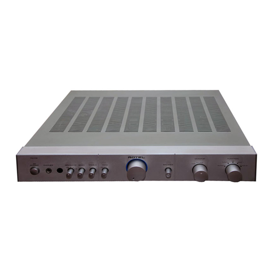
Quality Uncompromised
STEREO INTEGRATED AMPLIFIER
40 watts/ch
< 0.03% at rated power , 1/2 power or 1 watt
< 0.03% at rated power , 1/2 power or 1 watt
20Hz-15kHz, ±0.3dB
10Hz-40kHz, ±1dB
180
2.5mV / 47 kOhms
150 mV / 24 kOhms
180mV
5V
1V / 470 Ohms
±6 dB at 100Hz / 10kHz
80 dB
100 dB
115 Volts, 60 Hz
230 Volts, 50 Hz
220 W atts
435 x 72 x 342 mm
1
7
1
17
/
x 2
/
x 13
/
8
8
3
60 mm / 2
/
"
8
5.9 kg, 13 lbs.
®
RA-02
"
2
Serial. NO.
Beginning
Y-362A-0207/pdf
Advertisement
Table of Contents

Related Manuals for Rotel RA-02


Summary of Contents for Rotel RA-02
- Page 1 Quality Uncompromised ® T echnical STEREO INTEGRATED AMPLIFIER RA-02 Manual Table of Contents Specification........1 Parts List ...........2~5 Adjustment........6 Wiring Diagram ........ 7~8 PCB Assembly ........9 Schematic Diagram ......10~11 Specifications Continuous Power Output 40 watts/ch (20-20 kHz, < 0.03%, 8 ohms) Total Harmonic Distortion (20Hz - 20kHz) <...
- Page 2 POWER BASS TREBLE BALANCE PHONES SPEAKERS TONE PHONO AUX 2 ± EXT REM 12V TRIGGER OUT When servicing INTEGRATED AMPLIFIER PHONO AUX 2 TAPE 1 PRE OUT MODEL NO. RA-02 POWER CONSUMPTION: 220W SPEAKER A SPEAKER B LEFT RIGHT LEFT...
- Page 3 Parts List 1/3 RA-02 SYMBOL PARTS NO. DESCRIPTION 016 X-1326A01-06 PCB ASSY 501 X-1326 PCB ASSY PJ1,PJ5 066 4TR-2166#4 2P PIN JACK AU (WHT.RED) HJ2-5 065 YKB21-5103A 3.5Φ MINI JACK PJ2-PJ4 066 4TR-2408#3 4P PIN JACK AU (WHT.RED) R917 053 CR14-104J-A...
- Page 4 Parts List 2/3 SYMBOL PARTS NO. DESCRIPTION D701-705 034 SEL2E10C LED (BLUE) 1X5 C613,614,704 044 KT18-2A104K M.P CAPACITOR MKT1818-410/015 R405,406 054 TMFR401K2 METAL FILM RESISTOR 1/4W 1.2K R533,534 054 TMFR4100R METAL FILM RESISTOR 1/4W 100 R417,418,525,526 054 TMFR4100K METAL FILM RESISTOR 1/4W 100K R635,636 054 TMFR4012K METAL FILM RESISTOR 1/4W 12K...
- Page 5 Parts List 3/3 SYMBOL PARTS NO. DESCRIPTION S701 062 C-4174A13 ROTARY SWITCH SRRM1C7900 (FUNCTION) S501,502 062 4TR-2780 ROTARY SWITCH SRRZS42N23 (MONITOR, TONE) S601 062 4TR-3089 ROTARY SWITCH SRRZS44N01(SPEAKER) VR601,602 051 SFR002-222 SEMI-FIXED RESISTOR 2.2KB C901 044 DE1307E472M SPARK KILLER 4700pF L601,602 021 TRL-332 SPEAKER COIL 1F 23T...
-
Page 6: Case Outlines
Adjustment RA-02 Instruments : DC milli–voltmeter Notes : Prior to Bias Adjustment, run about 5minutes with rated output(8ohms) and warm up Power Transistor and Heat Sink. Set input off. Step Coupling Location Adjust Adjust for X-1341-01 PCB VR601 DC milli–voltmeter reads 4mV... - Page 7 RA-02...
- Page 8 Memo...
- Page 9 PCB Assembly RA-02...
- Page 10 Schematic Diagram - 1 RA-02...
- Page 11 Schematic Diagram - 2 RA-02...
Need help?
Do you have a question about the RA-02 and is the answer not in the manual?
Questions and answers