Life Fitness X5 Assembly Instructions Manual
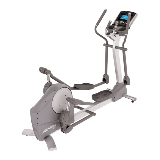
Total body elliptical cross trainer
Hide thumbs
Also See for X5:
- Owner's manual (28 pages) ,
- Assembly & operation manual (28 pages) ,
- User manual (23 pages)

Related Manuals for Life Fitness X5


Summary of Contents for Life Fitness X5
- Page 1 X 5 T O T A L - B O D Y E L L I P T I C A L C R O S S - T R A I N E R A S S E M B L Y I N S T R U C T I O N S...
- Page 2 EADQUARTERS 5100 North River Road Schiller Park, Illinois 60176 • U.S.A. www.lifefitness.com NTERNATIONAL FFICES LIFE FITNESS ASIA PACIFIC LTD LIFE FITNESS IBERIA LIFE FITNESS UK LTD Room 2610, Miramar Tower Pol. Ind. Molí dels Frares. c/C, nº 12 Queen Adelaide 132 Nathan Road 08620 Sant Vicenç...
- Page 3 Before using this product, it is essential to read this ENTIRE operation manual and ALL installation instructions. This will help in setting up the equipment quickly and in instructing others on how to use it correctly and safely. FCC Warning - Possible Radio / Television Interference NOTE: This equipment has been tested and found to comply with the limits for a Class B digital device, pursuant to part 15 of the FCC rules.
-
Page 4: Table Of Contents
How To Stabilize The Life Fitness Cross-Trainer ........ - Page 5 This Manual describes the assembly of the following products: Life Fitness Cross-Trainer: Statement of Purpose: The Cross-Trainer is an exercise machine that combines low-impact elliptical pedaling with push/pull arm motion to provide an efficient, effective total body workout. Health-related injuries may result from incorrect or excessive use of exercise equipment. The manufacturer STRONGLY recommends seeing a physician for a complete medical exam before undertaking an exercise program, particularly if the user has a family history of high blood pressure or heart disease;...
- Page 6 If any parts are missing, contact Life Fitness Customer Support Services at the number listed on page 26 of this assembly instruction booklet.
-
Page 7: Important Safety Instructions
• To reduce the risk of burns, fire, electric shock or injury, always connect each product to a properly grounded electrical outlet. • Never operate a Life Fitness product if it has a damaged power cord or electrical plug, or if it has been dropped, damaged, or even partially immersed in water, Contact Life Fitness Customer Support Services. - Page 8 • Keep all loose clothing, shoelaces and towels away from moving parts. • Keep the Life Fitness product away from walls and clear of any obstructions and furniture. Ensure that there is at least one foot clearance in front of the Cross-Trainer.
-
Page 9: Parts Description
ARTS ESCRIPTION Phillips Pan Head Screw – Clevis Cover & Front Shroud Fastener ......Qty: 12 10-32 x 3/8"... -
Page 11: Setup
ETUP Tools required: Socket set, Phillips Screwdriver, 9/16" open end wrench Please read instructions carefully before assembly. Be sure to assemble the unit where it is to be used. Remove the machine from packaging. Carefully lay out and count each part before assembly. Refer to the parts list on page 9 of this manual. - Page 12 4. Insert two (#4) 5 " bolts and two (#7) washers into the back- side of the connector joint on the base frame (B). Connect with two (#7) washers and two(#6) high profile nylon lock nuts. Start each bolt, and then tighten with a 9/16 " socket wrench.
- Page 13 1. Attach front shroud (E) to base-frame (B) using eight (#1) Phillips pan head screws (4 on each side). Using a Phillips screwdriver, secure the shrouds to the base frame (B). Repeat for the oppo- site side (same four locations). 2.
- Page 14 Attach Plastic Upright Cap to upright assembly: 1. Push the Plastic Upright Cap (F) into the open end of the tube at the top of the upright tube assembly (A). 2. Line up the hole in Plastic Upright Cap (F) with hole in upright tube assembly and fasten with a (#3) screw.
- Page 15 Attach accessory tray to upright assembly: 1. Feed the upper wire harness (G) through the slot in the accessory tray bracket (H). 2. Line up the holes on the accessory tray bracket (H) with the holes on the console plate (J), and then secure the accessory tray with the two (#2) self-tapping screws using a Phillips screw- driver.
- Page 16 Plug cables into the back of display console: 1. Plug the 10-pin connector at the end of the upper wire harness into the 10-pin connector (10P) in the back of the display console (K). Make sure the connector snaps into place.
- Page 17 Attach the display console to the console plate: 1. Line up the four holes in the back of the console plate (J) with the four holes in the back of the display console (K). 2. Attach the display console (K) using the four (#2) screws. Be careful not to pinch cables between the console and the con- sole plate.
- Page 18 Connect the pedal levers to the upper arms: 1. Insert pedal lever (L) into the clevis bracket (M) of the upper arm (N). 2. Connect the pedal lever (L) to the upper arm (N) using one (#5) 3 1/4" bolt and one (#6) high profile nylock nut. Using a 9/16" socket wrench, and a 9/16"...
-
Page 19: How To Stabilize The Life Fitness Cross-Trainer
ROSS RAINER Your Life Fitness Cross-Trainer comes with a standard U.S. power sup- ply. Insert the power adapter jack into the barrel plug on the back of the Cross-Trainer. Then insert the transformer into the wall outlet (or the uni- versal power supply if outside the U.S.). - Page 20 Life Fitness offers a full line of premier fitness equipment for the home. T O T A L - B O D Y E L L I P T I C A L C R O S S - T R A I N E R S | T R E A D M I L L S | L I F E C Y C L E E X E R C I S E B I K E S ®...
Need help?
Do you have a question about the X5 and is the answer not in the manual?
Questions and answers