
Related Manuals for Omega FMG600 Series


Summary of Contents for Omega FMG600 Series
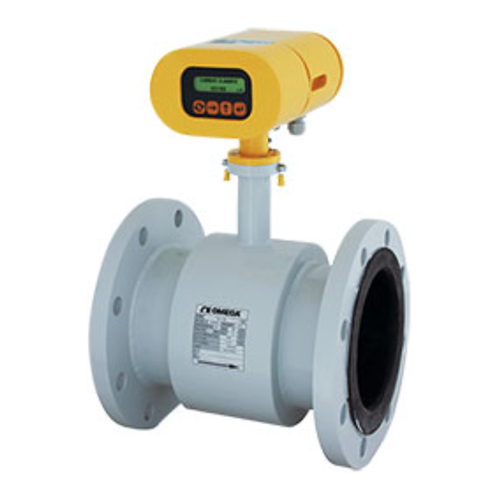
- Page 1 User’ s Guide Shop online at omega.com e-mail: info@omega.com For latest product manuals: omegamanual.info FMG600 Series Electromagnetic Flow Meters...
- Page 2 Approach Directives. OMEGA will add the CE mark to every appropriate device upon certification. The information contained in this document is believed to be correct, but OMEGA accepts no liability for any errors it contains, and reserves the right to alter specifications without notice.
-
Page 3: Table Of Contents
Design, Assembly and Service Manual Page 1 of 44 Induction flow meter FMG600 series Content 1. APPLICATION ............................. 2 2. MEASUREMENT PRINCIPLE ........................2 3. TECHNICAL DESCRIPTION ........................3 3.1. G .................................. 3 ENERAL 3.2. M ................................ -
Page 4: Application
Should the need arise; the user may combine any sensor of the FMG600 series with any electronic units without re-calibration of the meter on a test stand. The only thing that needs be done is to enter into the electronic unit memory the calibration constants and excitation frequency of the selected sensor;... -
Page 5: Technical Description
Design, Assembly and Service Manual Page 3 of 44 Induction flow meter FMG600 series As the magnetic flux density and distance between the electrodes are constant, the induced voltage is proportional to the liquid flow velocity in the tube. The value of the volume flow rate can then be readily determined as a product of the flow velocity and square section of the tube, Q = v x S. -
Page 6: Compact Version
Design, Assembly and Service Manual Page 4 of 44 Induction flow meter FMG600 series Dimensions of the box to accommodate separate electronic unit and the mounting bracket 6" (152) 7,9" (200) 6,8" (173) 9,45" (243) 1,4" (35) 2,4" (60) 3.2.2. Compact version... -
Page 7: Technical Parameters
Design, Assembly and Service Manual Page 5 of 44 Induction flow meter FMG600 series 4. TECHNICAL PARAMETERS 4.1. Flow sensor 4.1.1. Selection of correct sensor size The following table shows minimum and maximum flow rates for various sensor sizes and flow velocities ranging from 0.33 to 32.81 ft/s (0.1 to 10 m/s). -
Page 8: Operational Pressure Of Measured Liquid
PN 10 (1.0 MPa) 145 PSI 4.1.3. Selection of electrode material Standard electrodes made of Hastelloy C4. However, in special applications it may be necessary to select a different material. On request, Omega can supply electrodes made of tantalum -TGE. 4.1.4. Sensor tube lining Teflon Teflon (PTFE) lining is a universal solution for highly corrosive liquids and temperatures ranging from -4 °F... -
Page 9: Dimensions Of Flanged Sensor
Design, Assembly and Service Manual Page 7 of 44 Induction flow meter FMG600 series 4.1.6. Dimensions of flanged sensor Sensor dimensions for various rated diameters Line size (DN) Flanges according standard ANSI B 16.5 150 lb/sq.in. Nom. size DN Weight... -
Page 10: Dimensions Tri Clover Sensor
Design, Assembly and Service Manual Page 8 of 44 Induction flow meter FMG600 series 4.1.7. Dimensions Tri Clover sensor Tri-Clover l / s / hour Size DN/OD Qmin Qmax Qmin Qmax Qmin Qmax Qmin Qmax Inch (mm) ½ (12.70) 9.40 0.1094... -
Page 11: Flow Sensor Specifications
Design, Assembly and Service Manual Page 9 of 44 Induction flow meter FMG600 series 4.1.8. Flow sensor specifications Sensor size Flanged sensors, ½ “ to 12 “ (DN 15 to DN 300) Tri Clover, ½ " to 2 ½ "... -
Page 12: Electronic Unit Specifications
Design, Assembly and Service Manual Page 10 of 44 Induction flow meter FMG600 series 4.2.1. Electronic unit specifications Power source 230 V~ (+10 % / -15 %) / 50 ÷ 60 Hz optional 115 V~ (+10 % / -15 %) / 50 ÷ 60 Hz optional 24 V~ (+10 % / -15 %) / 50 ÷... -
Page 13: Meter Application Rules
Design, Assembly and Service Manual Page 11 of 44 Induction flow meter FMG600 series 5. METER APPLICATION RULES 5.1. Sensor placement in piping No chemical injection or batching unit (such as chlorine compound injector) should be located at the input side of the sensor. - Page 14 Design, Assembly and Service Manual Page 12 of 44 Induction flow meter FMG600 series In the cases where the liquid is pumped, the flow sensor shall always be placed at the output side of the pump to prevent underpressure in the piping which might damage the sensor. The required length of the straight piping section between the pump and sensor is then at least 25 DN.
- Page 15 Design, Assembly and Service Manual Page 13 of 44 Induction flow meter FMG600 series Elektrode axis Electrode axis Sensor mounted in a vertical position In the cases where the sensor is mounted in a vertical position, the flow direction shall always be upwards.
-
Page 16: Sensor Grounding
Design, Assembly and Service Manual Page 14 of 44 Induction flow meter FMG600 series Make sure that the adjoining piping is clamped/supported as close to the sensor as possible, to prevent vibrations and damage to the sensor. Undesirable sensor vibrations... -
Page 17: Tri Clover
Design, Assembly and Service Manual Page 15 of 44 Induction flow meter FMG600 series 5.2.2 Tri Clover Tri Clover Flange earthing connection Additional earthing With a remote version, it is recommended to electrically connect flow sensor with electronics housing box... -
Page 18: Flow Meter Installation And Operational Start
Design, Assembly and Service Manual Page 16 of 44 Induction flow meter FMG600 series 6. FLOW METER INSTALLATION AND OPERATIONAL START The meter installation work shall be performed in strict observance of the procedures and rules described in this manual. -
Page 19: Electric Connections Of Induction Flow Meter
Design, Assembly and Service Manual Page 17 of 44 Induction flow meter FMG600 series 6.2. Electric connections of induction flow meter The terminals for connecting cables can be accessed upon removal of a cover at the rear part of the box housing the electronic unit. -
Page 20: Output Signal Connections
Design, Assembly and Service Manual Page 18 of 44 Induction flow meter FMG600 series 6.2.2. Output signal connections Terminal Polarity Function Comments Switching contact Change-over contact Optocoupler contacts. Central contact Output relay 0,3 A, 30 VDC Break contact - pole Current output Active output, loading Rz max. -
Page 21: Connection Between Sensor And Electronic Unit (Remote Meter Version, Protection Class Ip 68)
The induction flow meter of either compact or remote design shall first be fitted mechanically and then the power supply and output terminals interconnected. Then switch on the power voltage. For a short while, the meter display will read WELCOME TO OMEGA FMG600 SERIES. Then one of the items of the DISPLAYED DATA menu will appear. -
Page 22: Operational Data
Design, Assembly and Service Manual Page 20 of 44 Induction flow meter FMG600 series 6.5.2. Operational data meter includes two-line alpha-numeric display characters with a background illumination. The display illumination function works in a power-saving mode where the illumination is automatically switched off 120 seconds following the last push-button action. On depressing any push-button, the display background illumination is reactivated. - Page 23 Design, Assembly and Service Manual Page 21 of 44 Induction flow meter FMG600 series 4. Total difference The difference between fluid volumes passed in the positive (+) and negative (-) directions since the measurement start, or temporary difference from the last resetting of the temporary difference data.
-
Page 24: Display Formats Of Aggregate Values
Design, Assembly and Service Manual Page 22 of 44 Induction flow meter FMG600 series The error messages are: E0: No error. E1: Error in CRC EEPROM. Incorrect data check sum in the EEPROM unit. This error may occur when the processor, following a power failure, does not manage to store all data in the EEPROM unit. -
Page 25: Programming
Design, Assembly and Service Manual Page 23 of 44 Induction flow meter FMG600 series 7. PROGRAMMING The induction flow meter can be programmed in two ways: using a computer connected to the serial meter interface, or using its own keyboard. The following description concerns the keyboard (push-button) programming procedures. -
Page 26: Programming Of The Basic Menu Items
Design, Assembly and Service Manual Page 24 of 44 Induction flow meter FMG600 series The two-line display will always show two of the following basic menu options: Displayed data Samples Analog output Output function Electrode clean Serial line Production data... -
Page 27: Samples
Design, Assembly and Service Manual Page 25 of 44 Induction flow meter FMG600 series Comment: The measurement unit selected for “Flow Rate” is automatically set for all other flow-rate quantities referred to in the Programming menu. The measurement unit selected for “Total Volume +” is automatically set for all other flow-volume quantities in the Programming menu. -
Page 28: Analog Output
Design, Assembly and Service Manual Page 26 of 44 Induction flow meter FMG600 series Current flow rate Average flow rate Sampling Suppression of step changes in flow rate Menu: Number of samples, depress The display will read “Number of samples xxx“. Replace xxx by a number from the range of 1 to 255 (usually 25). - Page 29 Design, Assembly and Service Manual Page 27 of 44 Induction flow meter FMG600 series Qmax and confirm the setting by depressing . The display will then read “Value entered Press any key”. Press any key, preferable the pusch-button. This action will take you back to the main programming menu, item “Analog output”.
- Page 30 Design, Assembly and Service Manual Page 28 of 44 Induction flow meter FMG600 series Examples of analog output interconnections Equipment with a current input Equipment with current inputs Outputs 1 and 2 serving the purpose of identifying fluid flow direction.
-
Page 31: Output Function
Design, Assembly and Service Manual Page 29 of 44 Induction flow meter FMG600 series Equipment with voltage input Current output connected as a voltage source to feed the (passive) output 2 The output voltage for the associated equipment is defined as the voltage drop on resistor R. It holds: U = I R. - Page 32 Design, Assembly and Service Manual Page 30 of 44 Induction flow meter FMG600 series Menu: Output function, depress The display will offer the following selection: OUT1 function OUT2 function RELAY function The two-line display unit will always show two of the items from the following menu. Use push-buttons to page downwards and upwards through the menu items.
- Page 33 Design, Assembly and Service Manual Page 31 of 44 Induction flow meter FMG600 series Pulse outputs In any of the pulse modes, an pulse will be generated as soon as a defined (preset) fluid volume passes through meter sensor. impulse...
- Page 34 0.264172037 gall = 1 l pulse width = 100 ms 15.85032224 gall/min = 60 l/min minimum gap length = 100 ms f <= 5Hz Impulse number selection for FMG600 SERIES for sensors Tri Clover Imp.number Qmax Dimension Qmax coefficient Imp.number...
- Page 35 Design, Assembly and Service Manual Page 33 of 44 Induction flow meter FMG600 series Frequency outputs In the frequency modes, the output signals will be impulses of impulse-to-gap ratio 1:1. The frequency range available is from 1Hz to 10kHz. Comment: The electronic unit of the meter includes only one frequency generator. It is therefore impossible to select different frequencies for each output, or combine the fixed-frequency mode at one output with frequency related to flow rate mode at the other output.
-
Page 36: Electrode Cleaning
This increases the contact resistance between the electrode and the measured fluid and results in decreased measurement accuracy. The FMG600 SERIES flow meter offers a sensor electrode cleaning function without sensor dismantling. The cleaning method is based on the electro-chemical phenomenon... -
Page 37: Serial Line
Design, Assembly and Service Manual Page 35 of 44 Induction flow meter FMG600 series where the electrodes are connected to an AC voltage source causing the accumulated layer to dissolve in the measured fluid. It is recommended that the cleaning process be repeated in regular intervals. - Page 38 Design, Assembly and Service Manual Page 36 of 44 Induction flow meter FMG600 series number of meter stations and cable length can further be increased. The cable wires are to be connected to terminals 6 and 7. The flow meter found at the end of the communication network shall be provided with jumper W1 with a terminal resistor 120 R.
-
Page 39: Production Data
Design, Assembly and Service Manual Page 37 of 44 Induction flow meter FMG600 series Menu: Serial line, depress / Baud rate, depress All equipment connected to a particular communication line branch shall use the same communication speed. There are five optional selections of speed:... - Page 40 Design, Assembly and Service Manual Page 38 of 44 Induction flow meter FMG600 series The display will read “Production date dd mm rrrr”. This information cannot be edited. To return to the Production data menu, depress any push-button, for example .
-
Page 41: Dose Setting
Design, Assembly and Service Manual Page 39 of 44 Induction flow meter FMG600 series The display will read “[CZ] Czech / [EN] English“. To page through the menu items, use push-buttons (direction downwards) and (upwards). Select the desired language and depress . -
Page 42: Zero Setting
Design, Assembly and Service Manual Page 40 of 44 Induction flow meter FMG600 series any key, preferably . The basic programming menu will reappear on the display with the “Dose Setting” item selected. 7.1.9. Zero setting The zero-setting function is useful in the cases where the actual flow rate is very small (e.g. due to leakage in closed valves) and for all practical purposes equal to zero. - Page 43 Design, Assembly and Service Manual Page 41 of 44 Induction flow meter FMG600 series EXIT New password Page through the menu using push-buttons (direction downwards) and (upwards). The selected menu item appears on the first line with the first character blinking. Select “EXIT” and depress .
-
Page 44: The Parameter Setting Menu
Design, Assembly and Service Manual Page 42 of 44 Induction flow meter FMG600 series 7.2. The Parameter setting menu Flowrate Do not display Total volume + Total volume - l/min 0.00 Total difference l/hour 0.000 m3/s 0.0000 Operational time m3/min 0.00000... -
Page 45: The Production Data Menu
Design, Assembly and Service Manual Page 43 of 44 Induction flow meter FMG600 series 7.3. The Production Data menu AFTER PASSWORD ENTRY BASIC PROGRAMMING MENU Displayed data Samples Analog output Output function Electrode clean Serial line Production data Production date... -
Page 46: Standard Tests
15-hour burn-in operation cycle. 9. CALIBRATION AND VERIFICATION TESTS The FMG600 SERIES induction flow meters are supplied from the manufacturing plant calibrated at three points on the meter characteristic. - Page 47 Department will issue an Authorized Return (AR) number immediately upon phone or written request. Upon examination by OMEGA, if the unit is found to be defective, it will be repaired or replaced at no charge. OMEGA’s WARRANTY does not apply to defects resulting from any action of the purchaser, including but not limited to mishandling, improper interfacing, operation outside of design limits, improper repair, or unauthorized modification.
- Page 48 Where Do I Find Everything I Need for Process Measurement and Control? OMEGA…Of Course! Shop online at omega.com TEMPERATURE Thermocouple, RTD & Thermistor Probes, Connectors, Panels & Assemblies Wire: Thermocouple, RTD & Thermistor Calibrators & Ice Point References Recorders, Controllers & Process Monitors...
Need help?
Do you have a question about the FMG600 Series and is the answer not in the manual?
Questions and answers