Advertisement
Quick Links
Advertisement

Related Manuals for Worcester DANESMOOR


Summary of Contents for Worcester DANESMOOR
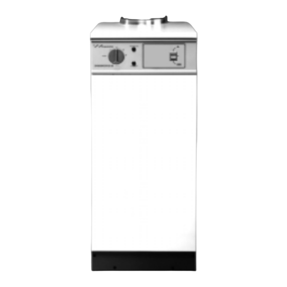
- Page 1 DANESMOOR SYSTEM BOILER INSTALLATION AND SERVICING INSTRUCTIONS...
- Page 4 Flue Center 370 mm 600 mm 92mm 1. Central heating flow (22mm compression). 2. Central heating return (1" BSP). 3. Gravity feed flow/optional air vent point (1" BSP). 4. Pressure relief discharge pipe (15mm compression).
- Page 6 Manual reset over- heat thermostat phial Split pin Automatic reset high limit thermostat phial Control thermostat phial Manual air vent Fire valve clip Electrical Top panel top cover Manual reset overheat Central heating thermostat flow Pressure relief valve User operating switch Expansion (Optional programmer vessel...
- Page 7 Manual reset over- heat thermostat phial Split pin Automatic reset high limit thermostat phial Control thermostat phial Manual air vent Rear air duct access cover Electrical Top panel top cover Rear air duct Manual reset overheat Central heating thermostat flow User operating switch Pressure (Optional programmer...
- Page 8 See Fig. 7 for FLUE GUARD Where possible take the flue terminating flue above the apex – if not positions. above the apex an anti down-draught terminal is advisable. ALWAYS TAKE THE FLUE ABOVE THE EAVES Brick Chimney. Use of a flue liner is recommended.
- Page 9 X = 180 mm Maximum 270 mm X = 307 mm Maximum FLUE GUARD One extension kit – X = 638 mm Maximum Two extension kits – X = 952 mm Maximum...
- Page 10 Terminal guard. See 7.4.5.
- Page 11 1 INLET 2 RETURN Cartridge filter 3 BLEED AND PRESSURE GAUGE PORT 4 VACUUM GAUGE PORT 5 PRESSURE ADJUSTMENT 6 NOZZLE OUTLET...
- Page 12 Maximum oil level Wall Paper element oil filter Oil tank Fire detection Filter Fire valve to element BS 5410 Full base (for plastic tanks) Isolating valve Isolating Isolating valve valve Burner Fire detection Non return Wall element valve Oil tank Filter Non return Isolating...
- Page 13 10mm or 12mm 10mm 10mm copper pipe copper pipe copper pipe bleed Turn fully clockwise Pipe support to isolate Open bracket grommet Blind grommet Isolating valve Isolating valve Flexible Turn fully oil hose clockwise Retaining to isolate clip 1/4" BSP female x 10/12mm compression coupling (not supplied)
- Page 14 Heating Flow (22 mm) Pressure Relief Valve Pump Expansion Vessel Heating Return (22 mm) Automatic by-pass valve to be fitted when thermostatic valves are fitted on all radiators Make up vessel Heating return Auto Heating return air vent Non return Non return Non return valve...
- Page 15 Mains supply 230/240V 50Hz E N L Brown Brown Earth Blue Stud Green/Yellow Blue Blue White Grey Green/Yellow High limit Manual reset Time clock Post purge thermostat thermostat white black 11 12 13 14 15 7 8 9 10 connecter connecter L N E E N 1 2 3 4 5 6 Brown...
- Page 16 Terminal strip 7 8 9 10 Pre-wired time clock terminal strip socket (Located in boiler electrical cover). Pre-wired time clock terminal strip plug (Connected to time clock leads). Blue 8 9 10 Programmer Note: Remove link plug 8 & 9.
- Page 17 External Pump (disconnect and remove) Remote Pre-wired 10 WAY JUNCTION BOX Junction Box OUTSIDE BOILER INSIDE BOILER Earth Neutral Permanent Live Pump (supplied in boiler) Switched Live 7 8 9 10 11 12 13 14 15 L N E E 2 3 4 5 6 Operating Switch Boiler socket...
- Page 18 E N L 7 8 9 1112 13 14 15 L N E E N 1 2 3 4 5 6 Hot Water Valve Honeywell V4043H Cylinder Thermostat Optional Worcester HEAT SYSTEMS Programmer TWICE TWICE HEATING WATER ONCE ONCE ADVANCE...
- Page 21 Locking screw Combustion head Photocell Spark gap 2.0-2.5 mm 10mm Adjusting disc Transformer Nozzle block Draught tube Nozzle Pressure Adjustment Screw Control box Oil pump Air control indicator Lockout reset button Air adjustment screw (4mm hexagonal head)
- Page 22 Locking screw Combustion head Spark gap 2 mm 2-2.5 mm Photocell 10 mm Adjusting disc Transformer Draught tube Nozzle Nozzle block Pressure Adjustment Screw Control box Oil pump Lockout reset button Air control indicator Air adjustment screw (4mm hexagonal head) Air control indicator Air adjustment screw Lockout...
- Page 23 Baffle retainer Baffle Heat shield ENSURE THAT ALL BAFFLES ARE FIRMLY SEATED IN POSITION...
- Page 24 Nozzle Assembly Check Valve...
- Page 25 LOCKOUT INDICATED BY RED LAMP ON CONTROL BOX To Re-set wait 2 minutes and press re-set button Ignition failure No oil delivery Air adjustment fault. Flame detection fault. Burner motor fails Intermittent Pulsation from nozzle. should be to operate. lockout. on start.
- Page 28 14 733a (11/07)
Need help?
Do you have a question about the DANESMOOR and is the answer not in the manual?
Questions and answers